EP0259913B1 - Driving signal for coarse servo employing sampled offset signal - Google Patents
Driving signal for coarse servo employing sampled offset signal Download PDFInfo
- Publication number
- EP0259913B1 EP0259913B1 EP87201557A EP87201557A EP0259913B1 EP 0259913 B1 EP0259913 B1 EP 0259913B1 EP 87201557 A EP87201557 A EP 87201557A EP 87201557 A EP87201557 A EP 87201557A EP 0259913 B1 EP0259913 B1 EP 0259913B1
- Authority
- EP
- European Patent Office
- Prior art keywords
- signal
- actuator
- fine
- coarse
- signals
- Prior art date
- Legal status (The legal status is an assumption and is not a legal conclusion. Google has not performed a legal analysis and makes no representation as to the accuracy of the status listed.)
- Expired - Lifetime
Links
- 230000003287 optical effect Effects 0.000 claims description 19
- 238000005070 sampling Methods 0.000 claims description 5
- 230000007274 generation of a signal involved in cell-cell signaling Effects 0.000 claims description 4
- 238000001514 detection method Methods 0.000 claims description 3
- 230000035945 sensitivity Effects 0.000 claims description 2
- 238000000034 method Methods 0.000 description 5
- 230000005855 radiation Effects 0.000 description 5
- 238000006073 displacement reaction Methods 0.000 description 3
- 239000000725 suspension Substances 0.000 description 3
- 230000000875 corresponding effect Effects 0.000 description 2
- 238000010586 diagram Methods 0.000 description 2
- 230000024121 nodulation Effects 0.000 description 2
- 230000010287 polarization Effects 0.000 description 2
- VOXZDWNPVJITMN-ZBRFXRBCSA-N 17β-estradiol Chemical compound OC1=CC=C2[C@H]3CC[C@](C)([C@H](CC4)O)[C@@H]4[C@@H]3CCC2=C1 VOXZDWNPVJITMN-ZBRFXRBCSA-N 0.000 description 1
- 238000002679 ablation Methods 0.000 description 1
- 230000008859 change Effects 0.000 description 1
- 239000002131 composite material Substances 0.000 description 1
- 238000010276 construction Methods 0.000 description 1
- 230000002596 correlated effect Effects 0.000 description 1
- 238000013500 data storage Methods 0.000 description 1
- 230000000694 effects Effects 0.000 description 1
- 238000005259 measurement Methods 0.000 description 1
- 230000037361 pathway Effects 0.000 description 1
- 230000004044 response Effects 0.000 description 1
- 230000001360 synchronised effect Effects 0.000 description 1
Images


Classifications
-
- G—PHYSICS
- G11—INFORMATION STORAGE
- G11B—INFORMATION STORAGE BASED ON RELATIVE MOVEMENT BETWEEN RECORD CARRIER AND TRANSDUCER
- G11B7/00—Recording or reproducing by optical means, e.g. recording using a thermal beam of optical radiation by modifying optical properties or the physical structure, reproducing using an optical beam at lower power by sensing optical properties; Record carriers therefor
- G11B7/08—Disposition or mounting of heads or light sources relatively to record carriers
- G11B7/09—Disposition or mounting of heads or light sources relatively to record carriers with provision for moving the light beam or focus plane for the purpose of maintaining alignment of the light beam relative to the record carrier during transducing operation, e.g. to compensate for surface irregularities of the latter or for track following
-
- G—PHYSICS
- G11—INFORMATION STORAGE
- G11B—INFORMATION STORAGE BASED ON RELATIVE MOVEMENT BETWEEN RECORD CARRIER AND TRANSDUCER
- G11B7/00—Recording or reproducing by optical means, e.g. recording using a thermal beam of optical radiation by modifying optical properties or the physical structure, reproducing using an optical beam at lower power by sensing optical properties; Record carriers therefor
- G11B7/08—Disposition or mounting of heads or light sources relatively to record carriers
- G11B7/085—Disposition or mounting of heads or light sources relatively to record carriers with provision for moving the light beam into, or out of, its operative position or across tracks, otherwise than during the transducing operation, e.g. for adjustment or preliminary positioning or track change or selection
- G11B7/08505—Methods for track change, selection or preliminary positioning by moving the head
-
- G—PHYSICS
- G11—INFORMATION STORAGE
- G11B—INFORMATION STORAGE BASED ON RELATIVE MOVEMENT BETWEEN RECORD CARRIER AND TRANSDUCER
- G11B7/00—Recording or reproducing by optical means, e.g. recording using a thermal beam of optical radiation by modifying optical properties or the physical structure, reproducing using an optical beam at lower power by sensing optical properties; Record carriers therefor
- G11B7/08—Disposition or mounting of heads or light sources relatively to record carriers
- G11B7/09—Disposition or mounting of heads or light sources relatively to record carriers with provision for moving the light beam or focus plane for the purpose of maintaining alignment of the light beam relative to the record carrier during transducing operation, e.g. to compensate for surface irregularities of the latter or for track following
- G11B7/0938—Disposition or mounting of heads or light sources relatively to record carriers with provision for moving the light beam or focus plane for the purpose of maintaining alignment of the light beam relative to the record carrier during transducing operation, e.g. to compensate for surface irregularities of the latter or for track following servo format, e.g. guide tracks, pilot signals
-
- G—PHYSICS
- G11—INFORMATION STORAGE
- G11B—INFORMATION STORAGE BASED ON RELATIVE MOVEMENT BETWEEN RECORD CARRIER AND TRANSDUCER
- G11B7/00—Recording or reproducing by optical means, e.g. recording using a thermal beam of optical radiation by modifying optical properties or the physical structure, reproducing using an optical beam at lower power by sensing optical properties; Record carriers therefor
- G11B7/08—Disposition or mounting of heads or light sources relatively to record carriers
- G11B7/09—Disposition or mounting of heads or light sources relatively to record carriers with provision for moving the light beam or focus plane for the purpose of maintaining alignment of the light beam relative to the record carrier during transducing operation, e.g. to compensate for surface irregularities of the latter or for track following
- G11B7/094—Methods and circuits for servo offset compensation
Definitions
- This invention relates to the field of servo signal generation for driving the coarse component of an actuating assembly which positions a beam of radiation with great accuracy over a moving surface containing information in tracks on that surface. It has particular application in the optical disk drive field where such drives include a linear actuator for driving an optical assembly radially over the disk and a fine servo actuator which directs the radiation beam to the optical assembly. It has application to drives with any sort of fine actuator system, including, at least, tilting mirror and two-axis linear optic driver motor fine actuators and any others in which displacement of the fine actuators causes a corresponding shift in the location of the returned beam spot on the detector.
- the coarse tracking actuator may be, for example, a linear voice coil motor with ball bearings or a sliding bearing, or a linear motor coupled across a pivot point to drive the optics in an arc approximately radially across the disk.
- fine tracking actuators are pivoting galvo (galvanic response driven) mirrors, a spring suspended linear fine servo motor, as for example, that set out in U.S. Pat. No. 4,587,466, and a rotating and sliding fine servo motor, such as that found in the Sony DISCMAN, a retail trade product available from Sony of Japan.
- the article 'On-land composite pregroove method for high density recordings' discloses a tracking systen which features a medium comprising servo segments having two different modulations, either with one area having no detectable nodulation or with both areas having different nodulations, similar to the medium of the invention. This allows tracking offset errors to be corrected.
- the problem of sensing the fine actuator position in a two stage system is not addressed.
- This invention teaches how to sense the "off center" position of a fine tracking actuator in an optical disk drive (compact disc player or recorder player combinations for data retrieval, etc.) by measuring shifts in the beam path without the addition of optical components, extra photodetectors or external sensors.
- the sensed "offset-from-center" position of the fine tracking actuator serves as input to a coarse actuator servo stage.
- Fig. 1 is a heuristic diagram for illustrating the effect of the actuator motor on the beam path.
- Figs. 2 and 3 are "cutouts" of Fig. 1, illustrating movement of the moveable assembly.
- Figs. 2A and 3A illustrate the returned beam spot on detector 22 corresponding to positions of the moveable assembly of Figs. 2 and 3, respectively.
- Fig. 4 is a segment of information track.
- Fig. 5 is another segment of information track.
- Fig. 6 is a diagramatic representation of the circuit elements used in generating the coarse actuator signal from the tracks of Figs. 4 or 5.
- Fig. 7 is a diagramatic representation illustrating how the position sensor fits into a random access disk system.
- Fig. 8 is a block diagramatic representation of an alternative coarse servo signal generation system.
- a portion of the rotating disk is designated with the numeral 10, and a laser and associated optics 11 produces a linearly polarized and collimated laser beam 12.
- the coarse actuator 13 drives the optical assembly 14 linearly in the directions indicated by arrow 15.
- the actuator 13 is described as a magnetizable rod 16 and a coil 17 arranged in such a way that energization of the coil 17 drives rod 16 in either of the directions indicated by arrow 15.
- the optical assembly 14 nominally comprises (for purposes of illustration) an objective lens element 18 (mounted to a moveable assembly 27), quarter wave plate 19, a beam splitter prism/mirror 20, an astigmatic lens 21, and a photo detector 22. All these elements (except the assembly 27) and the laser 11 are firmly fixed to the optical assembly 14.
- Fine actuator 23 is also represented (similarly to coarse actuator 13) by a moveable rod 24 surrounded by a coil 25 for purposes of illustration only.
- the movable assembly may be suspended magnetically or by springs or by the fine actuator or in other ways known to those in the art.
- the path traversed by the laser beam 12 begins with laser and optics 11 which directs the beam 12 to beam splitter-mirror 20, of which beam the polarization is made circular by quarter wave plate 19, passing to the objective lens 18 and then it impinges on the disk 10. Modulations of the disk surface influence the return beam 26, returning through lens 18 and then the polarization is 90° from its original orientation by quarter wave plate 19, it passes through the mirror of element 20, then through lens 21 to photodetector 22.
- Figs. 2, 3, 2A and 3A which are self-explanatory and employ elements of Fig. 1.
- Figs. 2 and 2A illustrate the situation where the actuator is centered and Figs. 3 and 3A show the situation where the actuator is off center with respect to the incoming (returned) laser beam.
- a tilting mirror may be moved by a fine actuator motor to deliver the beam between the laser, the disk and the detector. The invention herein described applies equally well to such systems.
- a segment of a track 30 is shown, which track is not defined by any ablation or change in height in the surface of the information bearing disk or structure, but is logically definable by a center line CL. On it may be written information for various purposes along the center line which information may be recorded as pits or spots of different optical properties than the rest of the information bearing surface, such as non-reflective pits 31 and 32.
- a segment such as segment S1 is used to generate tracking information for the fine servo motor control loop.
- this off-centered pit segment provides the sole indicator to generate track following signals, it must occur sufficiently often to provide such signals.
- This may be done either by using just the off-center pits at a high enough sampling rate or by employing it to correct a continuous, low frequency tracking signal by means of apparatus set forth in copending application Serial No. 760,440 filed on July 30, 1985 published as US-A- 4879708 and 4959823 or to generate a tracking signal similarly to the method explained in U.S. Patent No. 4,456,981, both incorporated herein by reference or in similar ways as are known to those in the art.
- the track 30 of Fig. 4 has no groove but is a logical line following center line CL.
- Off center modulations 33, 34, 35 and 36 will modulate the returned beam (26) to indicate to which side of the center line the beam spot is impinging on the disk.
- the sum signal for segment S1 is taken and sampled for left and right pit occurences.
- the signal from S2 would be used to determine the shift of the returned beam spot with respect to the detector and thus the fine actuator movement.
- Fig. 5 illustrates a different structure for the track which might also be used with this invention.
- a track groove 40 is centered around the center line of the track and has a depth of approximately one-eighth of the wavelength of the incident radiation beam used with the particular system.
- the deviation of an incident radiation beam from the center line of such a track groove may be used to generate a radial push-pull signal as is well known to one of ordinary skill in this art.
- a radial push-pull signal may be used to generate a radial push-pull signal as is well known to one of ordinary skill in this art.
- example of the push pull signal may be found in U.S. Patent Nos. 4,232,337; 4,209,804 and 4,100,557 incorporated herein by this reference.
- this track may include off-centered pits, for example 41, 42, 43 and 44, in segment S3, which may be used to adjust the radial push-pull signal to provide an accurate track off-center indicator for generating servo signals for the fine actuator as described above, or to generate an accurate tracking signal by themselves where the occurence is frequent enough.
- Segment S4 is an area of the disk which does not contain the grooved track, but is between two grooved parts of the track and functions in exactly the same manner as the segment S2 of Fig. 4.
- disk track formats can be used which do not employ the mirror areas shown as segments S2 and S4 of Figs. 4 and 5. This is true so long as the format includes structures from which two tracking signals may be derived: one which provides an indication of shifts of the beam relative to the detector and one which does not. The difference between these two tracking signals can be used as the signal sent to the coarse tracking loop.
- a preferred embodiment of the invention which is used with spring or magnetically suspended systems is described below with reference to Fig. 8. For example, a track having wobbled off-center pits and a continuous groove allows for a difference signal to be produced from the signals read from these two modulations which difference yields information on the shift of the returned beam spot on the split detector relative to the split. Referring now to Fig.
- the apparatus 119 receives input from detector 22 on the lines 114 and 115.
- the continuous difference of this input is generated by differential amplifier 121 on line 122.
- Sample and Hold gates 1 and 2 (125 and 126, respectively) permit the passing of a sum signal from amplifier 123 at the times of expected passage of left or right wobbled signals, indicated on enable lines l and r.
- the difference between these signals, given by differential amplifier 127, is provided as gain adjusted input to differential amplifier 128, whose other input is line 122.
- the output 129 is used as input to the coarse servo loop, as illustrated in Fig. 7.
- the optical pathway in a random access optical disk reader or reader/recorder is often not stable enough to assume safely that when the beam spot is centered on the detector the fine servo actuator is centered with respect to the coarse servo actuator.
- the low frequency (determinable over several sampled areas) component of the mirror area signal can be unreliable.
- a way to generate a reliable low frequency component is by using the low frequency content of the fine actuator drive signal (where the fine actuator is spring or magnetically suspended). This is because the drive signal is directly related to the displacement of the fine actuator.
- FIG. 6 a block diagram of an alternative coarse actuator signal generating means is shown and designated by the numeral 50.
- the information from the track areas shown in Figs. 4 and 5 will be taken from a reflected spot 51 on split-photo detector 22, the strength of whose signal is monitored (from each half) by a differential amplifier 53.
- Sample and hold gate 54 will permit only that part of the signal generated by amplifier 53 to pass which is synchronized with the mirror areas on the disk, i.e., segments S2 and S4 of Figs. 4 or 5.
- Methods of generating a synchronizing signal to allow only that portion of the signal which represents the mirrored areas are well known to those skilled in the art.
- the high frequency portion of this sampled signal is allowed to pass by high pass filter 55 (with representative elements thereof drawn therein but to be taken as illustrative elements only) to a summing amplifier 56 as signal A.
- the signal used to drive the fine servo motor is fed into low pass filter 58 by line 57 simultaneously with its input into the fine servo motor.
- the high and low pass filters should have the same corner cutoff frequency. (The cutoff lies below the natural resonant frequency of the mass-spring system of the fine actuator and its suspension system.)
- the output of the low pass filter 58 is gain adjusted by a gain stage 59, the gain setting being such that signals A and signals B have about the same sensitivity in terms of the ratio of voltage to distance.
- the gain adjustment should assure that if the (low frequency component of the) drive signal for the fine actuator is such that an increase of "a" volts in signal B would mean a movement of the spot on the disk (10) "ax” meters, then the shift in signal A should be “a” volts.
- the signal generated by summing amplifier 56 may be used as the only drive signal to drive the coarse servo actuator for tracking and seeking.
- the signal at line 60 may be used as input into the coarse actuator loop for tracking and seeking.
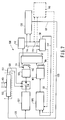
- Fig. 7 describes the relationship of the position sensor to the optical disk drive tracking and seeking control system 100.
- the microprocessor 102 may direct the seeking or tracking function of the disk drive. Seek may be accomplished by fine drive control line 108, which drives the fine amplifier 109 to drive the fine actuator 110 directly. (Seeking may be enabled by switch SW which is activated by line 151 to allow direct control of the fine actuator).
- Fine tracking compensation 107 provides phase margin in the fine tracking loop, which is necessary for a stable tracking loop.
- Coarse tracking compensation 105 does much the same thing with respect to the coarse tracking loop.
- the physical characteristics of the actuator and drive assembly through actuator dynamics 111 result in a feedback of the incident radiation beam from the disk to the system optics 112 by a physical path here only represented by line 113.
- the split detector 22 (as part of system optics 112) indicates the position of the beam spot 51 with respect to it and information located in the beam spot due to modulations of the disk, such information and centering being detectable through the coarse actuator signal generating means 50 which generates a signal on line 117 which is fed as a drive signal to coarse tracking compensation 105.
- a simplified version could take output from line 60 directly to drive the coarse servo. See line 60 in dotted on Fig. 7.
- This provides an alternative way of correcting the push-pull signal and to correct for optical misalignments.
- the fine actuator may not be centered, so it would have to adjust to its own spring forces. All in all, not a preferred embodiment.
- the coarse actuator is driven by a signal sensitive to the misalignment of the beam to the detector
- a signal can be used to drive the coarse actuator during seek, so long as the mirror areas are nested in radially aligned locations on the disk.
- Line 57 should come from a signal directly correlated to the fine actuator 110 drive signal in the preferred embodiment, line 111.
- System optics 112 by generating signals across lines 114 and 115 or their equivalent, allows in various ways for the construction of a fine actuator signal generator 130 (such as that described in the previously referenced U.S. Application Serial No. 760,440) and the signal output from this fine actuator signal generator will appear in properly amplified form on line 131. This signal will also be available for tracking error status detection or track count detection on line 120.
Landscapes
- Optical Recording Or Reproduction (AREA)
Description
- This invention relates to the field of servo signal generation for driving the coarse component of an actuating assembly which positions a beam of radiation with great accuracy over a moving surface containing information in tracks on that surface. It has particular application in the optical disk drive field where such drives include a linear actuator for driving an optical assembly radially over the disk and a fine servo actuator which directs the radiation beam to the optical assembly. It has application to drives with any sort of fine actuator system, including, at least, tilting mirror and two-axis linear optic driver motor fine actuators and any others in which displacement of the fine actuators causes a corresponding shift in the location of the returned beam spot on the detector.
- In practically all optical drives, including compact disc audio players, the information tracks on the disc are randomly accessed and followed by a servo system which incorporates a coarse and a fine tracking actuator. The coarse tracking actuator may be, for example, a linear voice coil motor with ball bearings or a sliding bearing, or a linear motor coupled across a pivot point to drive the optics in an arc approximately radially across the disk. Examples of fine tracking actuators are pivoting galvo (galvanic response driven) mirrors, a spring suspended linear fine servo motor, as for example, that set out in U.S. Pat. No. 4,587,466, and a rotating and sliding fine servo motor, such as that found in the Sony DISCMAN, a retail trade product available from Sony of Japan. (Spring suspension could mean suspension by rubber as is known to those in the art.)
To create a tracking servo system, the actions of the fine and the coarse actuators have to be coordinated in some manner. A common method is to follow the perceived movement of the fine servo motor. Using a sensor to determine the direction and/or amount of movement of the fine servo motor and the associated electronics increases the cost and complexity of the coarse actuator servo system. The sensing system may also work, for example, by measuring the average current supplied to the coil of the fine servo motor because that current is linearly related to the driving force; and in spring suspended systems, the driving force itself is linearly related to the displacement of the spring loaded or suspended mass (the mass being the mirror or optics and associated assembly) for frequencies below the natural mass-spring resonance frequency. While sensing the average current rather than the movement of the motor itself provides a lower cost method for generating servo information for the coarse actuator, because the mass-spring resonances are generally around 20 to 70 Hz, access actions occurring around 100 milliseconds (which are required for fast random access) do not allow enough time to average the fine servo motor current in such a way that the true fine servo motor movement can be sensed. - The use of the low frequency component of the fine servo drive signal to control the coarse servo is also known. See, for example, U.S. Reissue No. RE29,963 incorporated herein by reference (particularly see
column 1, lines 5, 12-30). The generation of samplable signals by use of a "mirror area" is described in EP-A-99576, incorporated herein by reference. - The article 'On-land composite pregroove method for high density recordings' (Optical Mass Data Storage II, Robert P Freese et al.,Proc.SPIE vol 695 August 1986, Bellingham, OS.) discloses a tracking systen which features a medium comprising servo segments having two different modulations, either with one area having no detectable nodulation or with both areas having different nodulations, similar to the medium of the invention. This allows tracking offset errors to be corrected. However the problem of sensing the fine actuator position in a two stage system is not addressed.
- This invention teaches how to sense the "off center" position of a fine tracking actuator in an optical disk drive (compact disc player or recorder player combinations for data retrieval, etc.) by measuring shifts in the beam path without the addition of optical components, extra photodetectors or external sensors. The sensed "offset-from-center" position of the fine tracking actuator serves as input to a coarse actuator servo stage.
- Fig. 1 is a heuristic diagram for illustrating the effect of the actuator motor on the beam path.
- Figs. 2 and 3 are "cutouts" of Fig. 1, illustrating movement of the moveable assembly.
- Figs. 2A and 3A illustrate the returned beam spot on
detector 22 corresponding to positions of the moveable assembly of Figs. 2 and 3, respectively. - Fig. 4 is a segment of information track.
- Fig. 5 is another segment of information track.
- Fig. 6 is a diagramatic representation of the circuit elements used in generating the coarse actuator signal from the tracks of Figs. 4 or 5.
- Fig. 7 is a diagramatic representation illustrating how the position sensor fits into a random access disk system.
- Fig. 8 is a block diagramatic representation of an alternative coarse servo signal generation system.
- Referring first to Fig. 1 in which the physical components of a system in which this invention functions are shown, a portion of the rotating disk is designated with the
numeral 10, and a laser and associatedoptics 11 produces a linearly polarized and collimatedlaser beam 12. Thecoarse actuator 13 drives theoptical assembly 14 linearly in the directions indicated byarrow 15. For illustration purposes only , theactuator 13 is described as amagnetizable rod 16 and acoil 17 arranged in such a way that energization of thecoil 17 drivesrod 16 in either of the directions indicated byarrow 15. Theoptical assembly 14 nominally comprises (for purposes of illustration) an objective lens element 18 (mounted to a moveable assembly 27),quarter wave plate 19, a beam splitter prism/mirror 20, anastigmatic lens 21, and aphoto detector 22. All these elements (except the assembly 27) and thelaser 11 are firmly fixed to theoptical assembly 14.Fine actuator 23 is also represented (similarly to coarse actuator 13) by amoveable rod 24 surrounded by acoil 25 for purposes of illustration only. The movable assembly may be suspended magnetically or by springs or by the fine actuator or in other ways known to those in the art. - The path traversed by the
laser beam 12 begins with laser andoptics 11 which directs thebeam 12 to beam splitter-mirror 20, of which beam the polarization is made circular byquarter wave plate 19, passing to theobjective lens 18 and then it impinges on thedisk 10. Modulations of the disk surface influence thereturn beam 26, returning throughlens 18 and then the polarization is 90° from its original orientation byquarter wave plate 19, it passes through the mirror ofelement 20, then throughlens 21 tophotodetector 22. - Many other optical paths may be used, so long as the movement of the fine actuator displaces the returning beam spot on the detector.
- To see how the shift of the beam spot may be recognized by the detector, see Figs. 2, 3, 2A and 3A which are self-explanatory and employ elements of Fig. 1. Figs. 2 and 2A illustrate the situation where the actuator is centered and Figs. 3 and 3A show the situation where the actuator is off center with respect to the incoming (returned) laser beam. Note also that in other beam paths in other systems a tilting mirror may be moved by a fine actuator motor to deliver the beam between the laser, the disk and the detector. The invention herein described applies equally well to such systems.
- Note that all drive signals (focus, data or information read signal, fine tracking and with this invention, coarse tracking) are derivable from a single detector. In some optical recorder/drive systems, two detectors are used (one for focus, one for tracking/read signals), and this invention may be applied in such systems, too, so long as one of the detectors is "split" in the correct orientation (such that the fine actuator movements cause the laser beams to shift in a direction perpendicular to the split).
- In Fig. 4, a segment of a
track 30 is shown, which track is not defined by any ablation or change in height in the surface of the information bearing disk or structure, but is logically definable by a center line CL. On it may be written information for various purposes along the center line which information may be recorded as pits or spots of different optical properties than the rest of the information bearing surface, such asnon-reflective pits - Note again Figs. 2, 3, 2A and 3A, and recognize that the shift of the
moving assembly 27 with respect to the return beam optical path is what causes the shift of thebeam spot 9 on thedetector 22. Subtracting the value of the outputs of the left and right sides of the split orquad photodetector 22, therefore, gives a signal related to this shift of the beam on the detector and thus the shift of the fine actuator (or moveable assembly) vis-a-vis the coarse actuator. Where off track center information is also present in the returned beam, a flat, nonmodulated area (segment S₂, S₄) of the disk's surface may be used to get a true signal to determine this off-centre measurement. Note that there must be enough S₂ type areas to allow for a sampling rate sufficient to assure stability of the coarse servo loop. - The
track 30 of Fig. 4 has no groove but is a logical line following center line CL. Offcenter modulations - Fig. 5 illustrates a different structure for the track which might also be used with this invention. In this structure, a
track groove 40 is centered around the center line of the track and has a depth of approximately one-eighth of the wavelength of the incident radiation beam used with the particular system. The deviation of an incident radiation beam from the center line of such a track groove may be used to generate a radial push-pull signal as is well known to one of ordinary skill in this art. Although many other low frequency tracking signals may be used, example of the push pull signal may be found in U.S. Patent Nos. 4,232,337; 4,209,804 and 4,100,557 incorporated herein by this reference. Again, this track may include off-centered pits, for example 41, 42, 43 and 44, in segment S₃, which may be used to adjust the radial push-pull signal to provide an accurate track off-center indicator for generating servo signals for the fine actuator as described above, or to generate an accurate tracking signal by themselves where the occurence is frequent enough. - Segment S₄ is an area of the disk which does not contain the grooved track, but is between two grooved parts of the track and functions in exactly the same manner as the segment S₂ of Fig. 4.
- Note that disk track formats can be used which do not employ the mirror areas shown as segments S₂ and S₄ of Figs. 4 and 5. This is true so long as the format includes structures from which two tracking signals may be derived: one which provides an indication of shifts of the beam relative to the detector and one which does not. The difference between these two tracking signals can be used as the signal sent to the coarse tracking loop. A preferred embodiment of the invention which is used with spring or magnetically suspended systems is described below with reference to Fig. 8. For example, a track having wobbled off-center pits and a continuous groove allows for a difference signal to be produced from the signals read from these two modulations which difference yields information on the shift of the returned beam spot on the split detector relative to the split. Referring now to Fig. 8 in which a coarse actuator drive
signal generating apparatus 119 is described, theapparatus 119 receives input fromdetector 22 on thelines differential amplifier 121 online 122. Sample and Holdgates 1 and 2 (125 and 126, respectively) permit the passing of a sum signal fromamplifier 123 at the times of expected passage of left or right wobbled signals, indicated on enable lines l and r. The difference between these signals, given bydifferential amplifier 127, is provided as gain adjusted input todifferential amplifier 128, whose other input isline 122. Theoutput 129 is used as input to the coarse servo loop, as illustrated in Fig. 7. - The optical pathway in a random access optical disk reader or reader/recorder is often not stable enough to assume safely that when the beam spot is centered on the detector the fine servo actuator is centered with respect to the coarse servo actuator. As a result, the low frequency (determinable over several sampled areas) component of the mirror area signal can be unreliable. A way to generate a reliable low frequency component is by using the low frequency content of the fine actuator drive signal (where the fine actuator is spring or magnetically suspended). This is because the drive signal is directly related to the displacement of the fine actuator.
- To see this, turn now to Fig. 6 in which a block diagram of an alternative coarse actuator signal generating means is shown and designated by the numeral 50. The information from the track areas shown in Figs. 4 and 5 will be taken from a reflected
spot 51 on split-photo detector 22, the strength of whose signal is monitored (from each half) by adifferential amplifier 53. Sample and holdgate 54 will permit only that part of the signal generated byamplifier 53 to pass which is synchronized with the mirror areas on the disk, i.e., segments S₂ and S₄ of Figs. 4 or 5.
Methods of generating a synchronizing signal to allow only that portion of the signal which represents the mirrored areas are well known to those skilled in the art. The high frequency portion of this sampled signal is allowed to pass by high pass filter 55 (with representative elements thereof drawn therein but to be taken as illustrative elements only) to a summingamplifier 56 as signal A. The signal used to drive the fine servo motor is fed intolow pass filter 58 byline 57 simultaneously with its input into the fine servo motor. The high and low pass filters should have the same corner cutoff frequency. (The cutoff lies below the natural resonant frequency of the mass-spring system of the fine actuator and its suspension system.) The output of thelow pass filter 58 is gain adjusted by again stage 59, the gain setting being such that signals A and signals B have about the same sensitivity in terms of the ratio of voltage to distance. In other words, the gain adjustment should assure that if the (low frequency component of the) drive signal for the fine actuator is such that an increase of "a" volts in signal B would mean a movement of the spot on the disk (10) "ax" meters, then the shift in signal A should be "a" volts. Thus the signal generated by summingamplifier 56 may be used as the only drive signal to drive the coarse servo actuator for tracking and seeking. For non spring and non magnetically suspended fine actuator, the signal atline 60 may be used as input into the coarse actuator loop for tracking and seeking. - Fig. 7 describes the relationship of the position sensor to the optical disk drive tracking and seeking
control system 100. When called upon through the interface to thecomputer 101, themicroprocessor 102 may direct the seeking or tracking function of the disk drive. Seek may be accomplished by finedrive control line 108, which drives thefine amplifier 109 to drive thefine actuator 110 directly. (Seeking may be enabled by switch SW which is activated byline 151 to allow direct control of the fine actuator).Fine tracking compensation 107 provides phase margin in the fine tracking loop, which is necessary for a stable tracking loop.Coarse tracking compensation 105 does much the same thing with respect to the coarse tracking loop. The physical characteristics of the actuator and drive assembly throughactuator dynamics 111 result in a feedback of the incident radiation beam from the disk to thesystem optics 112 by a physical path here only represented by line 113. Throughlines beam spot 51 with respect to it and information located in the beam spot due to modulations of the disk, such information and centering being detectable through the coarse actuator signal generating means 50 which generates a signal online 117 which is fed as a drive signal tocoarse tracking compensation 105. - Alternatively, a simplified version could take output from
line 60 directly to drive the coarse servo. Seeline 60 in dotted on Fig. 7. This provides an alternative way of correcting the push-pull signal and to correct for optical misalignments. As a result of using this alternative, however, the fine actuator may not be centered, so it would have to adjust to its own spring forces. All in all, not a preferred embodiment. - In any event, where the coarse actuator is driven by a signal sensitive to the misalignment of the beam to the detector, such a signal can be used to drive the coarse actuator during seek, so long as the mirror areas are nested in radially aligned locations on the disk.
- Note that the other input to coarse actuator signal generating means 50 is
line 57.Line 57 should come from a signal directly correlated to thefine actuator 110 drive signal in the preferred embodiment,line 111.System optics 112, by generating signals acrosslines line 131. This signal will also be available for tracking error status detection or track count detection online 120. - Note that in using this invention, one may center the fine actuator before starting tracking or seeking without an external sensor. This may be accomplished with the following steps. Start rotating the disk. Focus the beam spot on the information surface. Sample the mirror areas with the split detector, and send the resultant signal to the fine servo loop (that is, before enabling the coarse amplifier, use the signal from
line 117 to center the beam spot returned from the mirror areas). This resultant signal should be continuously available to sum with the fine actuator drive signal.
Claims (4)
- An information storage apparatus for beam scanning a medium (10) containing information tracks having first segments (S1) for generating tracking signals therefrom and second segments (S2) which are located on predetermined positions in the tracks and in which said tracks have no detectable modulation; the apparatus having a fine (23) and a coarse (13) actuator each having associated servo loops; wherein movement of the fine actuator (23) causes a shift in the location of the returned beam spot (9) on at least one split photo detector (22); first signal deriving means (130) for deriving a fine control signal for the fine actuator from the split photo detector (22) and second signal deriving means (50) for deriving a coarse control signal for the coarse actuator from the output signals of the split photo detector (22), which second signal deriving means (50) comprises means (114,115) for receiving the signals from either half of said split photo detector (22) and means (53) for deriving from said signals a difference signal; sample and hold gate means (54) for allowing to pass only that portion of the difference signal generated at the same time as a second segment detection signal, and wherein this difference signal indicative of the position of the fine actuator is fed into the coarse servo loop for the control of the position of the coarse actuator.
- An apparatus as claimed in Claim 1, wherein said means (50) for deriving the coarse control signal comprises high pass filter means (55) for passing the high frequency portion of the split detector difference signal, a low pass filter means (58) for passing the low frequency portion of a signal which is related to a spring or magnetically suspended fine actuator drive signal, means (59) for adjusting the gain of sensitivity of the signals coming from said low pass filter (58) and from said high pass filter (55), summing amplifier means (56) for generating a coarse actuator servo signal for tracking having as inputs the gain adjusted output of both said high pass filter means (55) and said low pass filter means (58).
- An information storage system comprising optical scanning means for beam scanning a medium containing information tracks having first and second servo segments for generating servo signals therefrom, wherein said first segments comprise modulations of the information track sufficient to indicate in a returned beam the deviation from track centre line of said return beam when said return beam impinges on a split photo detector means (22) and wherein said second segments have wobbled off-centre pits which also indicate the deviation from said centre line, said system having fine and coarse actuators (13) wherein the fine actuator (23) is spring or magnetically suspended, each actuator having associated servo loops wherein movements of the fine actuator (23) cause a shift in the location of the returned beam spot on at least one split detector and wherein a signal generation means (119) produces at least two signals, the first one (122), derived from the first segments, comprising a difference signal from either half of the split photodetector being sensitive to shift of the returned beam spot on the detector (22) vis-a-vis the split (22) and the second one, derived from the second segments, being not, but being sensitive to shifts of the beam spot on the disk vis-a-vis the track centre lines and being generated by means (123) for adding the output signals of the split detector so as to generate a sum signal, first means (125) for sampling the sum signal during the passage of a first one of the wobbled off-centre pits in the second segment, second means (126) for sampling the sum signal during the passage of a second one of the wobbled off-centre in the pits in the second segment, and means (127) for subtracting output signals of the first and second sampling means so as to generate the second one of the two signals, and wherein said signal generation means provides a difference (129) of the first and second one of the two signals produced by the signal generating means.
- A system as set forth in claim 3 comprising means for centering said fine actuator vis-a-vis the coarse actuator and means for performing, after the fine actuator has been centered by said centering means, the following steps :a) start rotating of media disk,b) set focus,c) sample alignment sensitive area signals,d) send signal from step c to fine actuator servo loop.
Applications Claiming Priority (2)
| Application Number | Priority Date | Filing Date | Title |
|---|---|---|---|
| US902350 | 1986-08-29 | ||
| US06/902,350 US4864552A (en) | 1986-08-29 | 1986-08-29 | Driving signal for coarse servo employing sampled offset signal |
Publications (3)
| Publication Number | Publication Date |
|---|---|
| EP0259913A2 EP0259913A2 (en) | 1988-03-16 |
| EP0259913A3 EP0259913A3 (en) | 1990-01-24 |
| EP0259913B1 true EP0259913B1 (en) | 1995-01-11 |
Family
ID=25415737
Family Applications (1)
| Application Number | Title | Priority Date | Filing Date |
|---|---|---|---|
| EP87201557A Expired - Lifetime EP0259913B1 (en) | 1986-08-29 | 1987-08-18 | Driving signal for coarse servo employing sampled offset signal |
Country Status (6)
| Country | Link |
|---|---|
| US (1) | US4864552A (en) |
| EP (1) | EP0259913B1 (en) |
| JP (1) | JP2738425B2 (en) |
| KR (1) | KR950010419B1 (en) |
| AU (1) | AU605171B2 (en) |
| DE (1) | DE3750975T2 (en) |
Families Citing this family (14)
| Publication number | Priority date | Publication date | Assignee | Title |
|---|---|---|---|---|
| JP2785290B2 (en) * | 1988-12-19 | 1998-08-13 | ソニー株式会社 | Optical disk seek and tracking device |
| JP2656371B2 (en) * | 1990-06-26 | 1997-09-24 | 富士通株式会社 | Optical disk drive |
| JPH0778975B2 (en) * | 1990-09-27 | 1995-08-23 | インターナシヨナル・ビジネス・マシーンズ・コーポレーシヨン | Optical disk drive |
| JPH04313818A (en) * | 1991-01-30 | 1992-11-05 | Pioneer Electron Corp | Actuator position detecting device, actuator position controller and track searching controller |
| JPH05307844A (en) * | 1992-05-01 | 1993-11-19 | Ricoh Co Ltd | Speed detector and speed controller |
| DE69330232T2 (en) * | 1992-07-31 | 2002-01-10 | Matsushita Electric Industrial Co., Ltd. | Device for the optical recording / reproduction of data |
| DE69323397T2 (en) * | 1992-11-20 | 1999-08-26 | Koninklijke Philips Electronics N.V. | Scanning device with a two-stage control for positioning a scanning point |
| EP0599392B1 (en) * | 1992-11-20 | 1999-02-03 | Koninklijke Philips Electronics N.V. | Scanning device with two-stage controller for positioning a scanning point |
| DE19743935A1 (en) * | 1997-10-04 | 1999-04-08 | Thomson Brandt Gmbh | Device for reading or writing to optical recording media |
| US6275349B1 (en) * | 1998-12-02 | 2001-08-14 | Storage Technology Corporation | Integrated optical tracking system for magnetic media |
| US6873482B1 (en) * | 1999-03-05 | 2005-03-29 | Yung-Chieh Hsieh | Magnetic recording drive with continuous magnetic servo system |
| US6587303B1 (en) * | 2000-06-09 | 2003-07-01 | International Business Machines Corporation | Servo control of a coarse actuator |
| US7035041B1 (en) * | 2002-02-12 | 2006-04-25 | Maxtor Corporation | Displacement resetting systems and methods for the second stage of a hard disk drive dual-stage actuator |
| US11735991B2 (en) * | 2018-10-19 | 2023-08-22 | Thk Co., Ltd. | Actuator |
Family Cites Families (35)
| Publication number | Priority date | Publication date | Assignee | Title |
|---|---|---|---|---|
| US29963A (en) * | 1860-09-11 | Improvement in wood-screws | ||
| US3381086A (en) * | 1962-08-16 | 1968-04-30 | Minnesota Mining & Mfg | Reproduction of television signals from photographic disc recordings |
| USRE29963E (en) | 1972-03-29 | 1979-04-10 | U.S. Philips Corporation | Servo system for reading from a disc-shaped record carrier containing signals coded in optical form |
| US4451913A (en) * | 1972-10-24 | 1984-05-29 | Discovision Associates | Video disc read back scanner |
| JPS5922289B2 (en) * | 1975-11-20 | 1984-05-25 | ソニー株式会社 | How to get started |
| NL7810462A (en) * | 1978-10-19 | 1980-04-22 | Philips Nv | REGISTRATION CONTAINER IN WHICH INFORMATION IS PRESENTED IN AN OPTICALLY READABLE RADIATION-REFLECTING INFORMATION STRUCTURE |
| US4232337A (en) * | 1978-12-13 | 1980-11-04 | Mca Discovision, Inc. | Method and apparatus for tracking an optically readable information track |
| JPS57147143A (en) * | 1981-03-07 | 1982-09-10 | Olympus Optical Co Ltd | Objective lens driving device |
| JPS5848243A (en) * | 1981-09-17 | 1983-03-22 | Mitsubishi Electric Corp | Device for tracking track of optical recorder and reproducer |
| US4443870A (en) * | 1981-10-15 | 1984-04-17 | Burroughs Corporation | Optical memory system providing track following |
| US4494226A (en) * | 1981-10-15 | 1985-01-15 | Burroughs Corporation | Three beam optical memory system |
| JPS5877036A (en) * | 1981-10-30 | 1983-05-10 | Olympus Optical Co Ltd | Detecting method of tracking error |
| NL8200208A (en) * | 1982-01-21 | 1983-08-16 | Philips Nv | DEVICE FOR READING A DISC REGISTRATION CARRIER. |
| US4435797A (en) * | 1982-02-17 | 1984-03-06 | Burroughs Corporation | Optical memory system having track following and seeking capabilities |
| US4456981A (en) * | 1982-03-19 | 1984-06-26 | Magnetic Peripherals Inc. | Modulation system for optical recording |
| JPS5919250A (en) * | 1982-07-21 | 1984-01-31 | Hitachi Ltd | Recording and reproducing device of optical information |
| US4587466A (en) * | 1982-12-09 | 1986-05-06 | Magnetic Peripherals | Two axis linear motor for optical focusing and tracking system in optical recording |
| JPS59116939A (en) * | 1982-12-23 | 1984-07-06 | Olympus Optical Co Ltd | Optical recording and reproducing device |
| JPS59215079A (en) * | 1983-05-20 | 1984-12-04 | Hitachi Ltd | positioning device |
| JPS6095733A (en) * | 1983-10-31 | 1985-05-29 | Hitachi Ltd | Optical signal processor |
| US4627039A (en) * | 1983-12-23 | 1986-12-02 | Magnetic Peripherals Inc. | Head positioning servo system for optical recording with coarse and fine control |
| JPS60143442A (en) * | 1983-12-28 | 1985-07-29 | Olympus Optical Co Ltd | Tracking system |
| JPH0690804B2 (en) * | 1984-01-20 | 1994-11-14 | 株式会社日立製作所 | Optical information recording / reproducing device |
| JPS60170035A (en) * | 1984-02-13 | 1985-09-03 | Toshiba Corp | Control signal production method for optical information reproducer |
| JPS60173131U (en) * | 1984-04-25 | 1985-11-16 | パイオニア株式会社 | Optical recording disc playback device |
| US4627038A (en) * | 1984-07-05 | 1986-12-02 | Storage Technology Partners Ii | Optical disk storage unit having a servo system with different velocity inputs |
| US4621351A (en) * | 1984-07-06 | 1986-11-04 | Storage Technology Partners Ii | Beam alignment system |
| JPS6185638A (en) * | 1984-10-03 | 1986-05-01 | Fuji Photo Film Co Ltd | Optical disc recording and reproducing method |
| JPS6171424A (en) * | 1984-09-14 | 1986-04-12 | Nippon Kogaku Kk <Nikon> | Tracking error detection device in optical information reproducing device |
| KR940002001B1 (en) * | 1985-03-22 | 1994-03-12 | 가부시끼가이샤 히다찌세이사꾸쇼 | Access method and information retrieval apparatus |
| US4748609A (en) * | 1985-03-29 | 1988-05-31 | Hitachi, Ltd. | Method and apparatus for composite tracking servo system with track offset correction and rotary optical disc having at least one correction mark for correcting track offset |
| US4745588A (en) * | 1985-04-16 | 1988-05-17 | Olympus Optical Co., Ltd. | Tracking control apparatus |
| NL193159C (en) * | 1985-06-19 | 1998-12-04 | Hitachi Ltd | Preformed record carrier for writing information therein by means of a light spot. |
| EP0215556B1 (en) * | 1985-07-30 | 1993-01-13 | Koninklijke Philips Electronics N.V. | Record carrier and tracking signal generator circuit |
| US4866688A (en) * | 1985-12-20 | 1989-09-12 | Hitachi, Ltd. | Composite tracking servo system for optical disc apparatus with track offset correction |
-
1986
- 1986-08-29 US US06/902,350 patent/US4864552A/en not_active Expired - Fee Related
-
1987
- 1987-08-18 EP EP87201557A patent/EP0259913B1/en not_active Expired - Lifetime
- 1987-08-18 DE DE3750975T patent/DE3750975T2/en not_active Expired - Fee Related
- 1987-08-28 JP JP62214948A patent/JP2738425B2/en not_active Expired - Lifetime
- 1987-08-28 AU AU77681/87A patent/AU605171B2/en not_active Ceased
- 1987-08-29 KR KR1019870009494A patent/KR950010419B1/en not_active Expired - Fee Related
Non-Patent Citations (1)
| Title |
|---|
| 59 215079 (HITACHI SEISAKUSHO K.K.) 04 December 1984, * |
Also Published As
| Publication number | Publication date |
|---|---|
| KR880003300A (en) | 1988-05-16 |
| EP0259913A2 (en) | 1988-03-16 |
| KR950010419B1 (en) | 1995-09-16 |
| AU605171B2 (en) | 1991-01-10 |
| JPS6369027A (en) | 1988-03-29 |
| EP0259913A3 (en) | 1990-01-24 |
| JP2738425B2 (en) | 1998-04-08 |
| US4864552A (en) | 1989-09-05 |
| DE3750975D1 (en) | 1995-02-23 |
| DE3750975T2 (en) | 1995-08-24 |
| AU7768187A (en) | 1988-03-03 |
Similar Documents
| Publication | Publication Date | Title |
|---|---|---|
| EP0080212B1 (en) | Optical memory apparatus | |
| EP0155077B1 (en) | Servo system | |
| US4809247A (en) | Video disc head tracking apparatus | |
| US4864552A (en) | Driving signal for coarse servo employing sampled offset signal | |
| US4805162A (en) | Fine and coarse servo system for access and tracking on an optical disk | |
| EP0191467B1 (en) | Optical disc apparatus | |
| US4703467A (en) | Video disc read back scanner | |
| US5444683A (en) | Optical reporting reproducing device having fixed and movable optical systems | |
| US4513406A (en) | Positioning servo circuit for a disk system | |
| US4684797A (en) | Optical system and method for reducing vibration of an objective lens in an optical head assembly of an optical read/write system | |
| US4977552A (en) | Split type optical pick-up device with a tracking error detector on the moving part | |
| EP0391691B1 (en) | Optical recording and reproducing appparatus | |
| KR0175653B1 (en) | Seeking and tracking device for optical discs | |
| JP2804118B2 (en) | Tracking control device | |
| US5606542A (en) | Optical pickup using three beam tracking method | |
| JPH0746428B2 (en) | Optical pickup | |
| JPH0457223A (en) | Optical recording/reproducing device | |
| US4454415A (en) | Tracking mirror assembly and control system for an optical data storage disc | |
| JPH0570210B2 (en) | ||
| JP3006987B2 (en) | Optical pickup | |
| JP2724185B2 (en) | Information processing device | |
| JP2789131B2 (en) | Magnetic head flying height control method for magneto-optical recording / reproducing device | |
| JPH0685220B2 (en) | Information track search device | |
| JPS6168735A (en) | Focus servo actuation device for optical recording and reproduction | |
| JPH0150974B2 (en) |
Legal Events
| Date | Code | Title | Description |
|---|---|---|---|
| PUAI | Public reference made under article 153(3) epc to a published international application that has entered the european phase |
Free format text: ORIGINAL CODE: 0009012 |
|
| AK | Designated contracting states |
Kind code of ref document: A2 Designated state(s): DE ES FR GB IT NL SE |
|
| PUAL | Search report despatched |
Free format text: ORIGINAL CODE: 0009013 |
|
| AK | Designated contracting states |
Kind code of ref document: A3 Designated state(s): DE ES FR GB IT NL SE |
|
| 17P | Request for examination filed |
Effective date: 19900719 |
|
| 17Q | First examination report despatched |
Effective date: 19920330 |
|
| RAP1 | Party data changed (applicant data changed or rights of an application transferred) |
Owner name: N.V. PHILIPS' GLOEILAMPENFABRIEKEN |
|
| GRAA | (expected) grant |
Free format text: ORIGINAL CODE: 0009210 |
|
| AK | Designated contracting states |
Kind code of ref document: B1 Designated state(s): DE ES FR GB IT NL SE |
|
| PG25 | Lapsed in a contracting state [announced via postgrant information from national office to epo] |
Ref country code: NL Effective date: 19950111 |
|
| REF | Corresponds to: |
Ref document number: 3750975 Country of ref document: DE Date of ref document: 19950223 |
|
| ITF | It: translation for a ep patent filed | ||
| PG25 | Lapsed in a contracting state [announced via postgrant information from national office to epo] |
Ref country code: SE Effective date: 19950411 |
|
| ET | Fr: translation filed | ||
| PG25 | Lapsed in a contracting state [announced via postgrant information from national office to epo] |
Ref country code: ES Free format text: LAPSE BECAUSE OF FAILURE TO SUBMIT A TRANSLATION OF THE DESCRIPTION OR TO PAY THE FEE WITHIN THE PRESCRIBED TIME-LIMIT Effective date: 19950422 |
|
| NLV1 | Nl: lapsed or annulled due to failure to fulfill the requirements of art. 29p and 29m of the patents act | ||
| PLBE | No opposition filed within time limit |
Free format text: ORIGINAL CODE: 0009261 |
|
| STAA | Information on the status of an ep patent application or granted ep patent |
Free format text: STATUS: NO OPPOSITION FILED WITHIN TIME LIMIT |
|
| 26N | No opposition filed | ||
| REG | Reference to a national code |
Ref country code: FR Ref legal event code: CD |
|
| PGFP | Annual fee paid to national office [announced via postgrant information from national office to epo] |
Ref country code: FR Payment date: 20010824 Year of fee payment: 15 |
|
| PGFP | Annual fee paid to national office [announced via postgrant information from national office to epo] |
Ref country code: GB Payment date: 20010831 Year of fee payment: 15 |
|
| PGFP | Annual fee paid to national office [announced via postgrant information from national office to epo] |
Ref country code: DE Payment date: 20011015 Year of fee payment: 15 |
|
| REG | Reference to a national code |
Ref country code: GB Ref legal event code: IF02 |
|
| PG25 | Lapsed in a contracting state [announced via postgrant information from national office to epo] |
Ref country code: GB Free format text: LAPSE BECAUSE OF NON-PAYMENT OF DUE FEES Effective date: 20020818 |
|
| PG25 | Lapsed in a contracting state [announced via postgrant information from national office to epo] |
Ref country code: DE Free format text: LAPSE BECAUSE OF NON-PAYMENT OF DUE FEES Effective date: 20030301 |
|
| GBPC | Gb: european patent ceased through non-payment of renewal fee |
Effective date: 20020818 |
|
| PG25 | Lapsed in a contracting state [announced via postgrant information from national office to epo] |
Ref country code: FR Free format text: LAPSE BECAUSE OF NON-PAYMENT OF DUE FEES Effective date: 20030430 |
|
| REG | Reference to a national code |
Ref country code: FR Ref legal event code: ST |
|
| PG25 | Lapsed in a contracting state [announced via postgrant information from national office to epo] |
Ref country code: IT Free format text: LAPSE BECAUSE OF NON-PAYMENT OF DUE FEES;WARNING: LAPSES OF ITALIAN PATENTS WITH EFFECTIVE DATE BEFORE 2007 MAY HAVE OCCURRED AT ANY TIME BEFORE 2007. THE CORRECT EFFECTIVE DATE MAY BE DIFFERENT FROM THE ONE RECORDED. Effective date: 20050818 |