EP0258843B1 - Method and apparatus for carrying out pulse-echo measurement - Google Patents
Method and apparatus for carrying out pulse-echo measurement Download PDFInfo
- Publication number
- EP0258843B1 EP0258843B1 EP87112562A EP87112562A EP0258843B1 EP 0258843 B1 EP0258843 B1 EP 0258843B1 EP 87112562 A EP87112562 A EP 87112562A EP 87112562 A EP87112562 A EP 87112562A EP 0258843 B1 EP0258843 B1 EP 0258843B1
- Authority
- EP
- European Patent Office
- Prior art keywords
- level
- power
- medium
- pulse
- elements
- Prior art date
- Legal status (The legal status is an assumption and is not a legal conclusion. Google has not performed a legal analysis and makes no representation as to the accuracy of the status listed.)
- Expired
Links
Images
Classifications
-
- G—PHYSICS
- G01—MEASURING; TESTING
- G01M—TESTING STATIC OR DYNAMIC BALANCE OF MACHINES OR STRUCTURES; TESTING OF STRUCTURES OR APPARATUS, NOT OTHERWISE PROVIDED FOR
- G01M11/00—Testing of optical apparatus; Testing structures by optical methods not otherwise provided for
- G01M11/30—Testing of optical devices, constituted by fibre optics or optical waveguides
- G01M11/31—Testing of optical devices, constituted by fibre optics or optical waveguides with a light emitter and a light receiver being disposed at the same side of a fibre or waveguide end-face, e.g. reflectometers
- G01M11/3109—Reflectometers detecting the back-scattered light in the time-domain, e.g. OTDR
- G01M11/3118—Reflectometers detecting the back-scattered light in the time-domain, e.g. OTDR using coded light-pulse sequences
Definitions
- This invention relates to a method and apparatus for carrying out a pulse-echo measurement (time domain reflectometry) and further relates to an information conveying method.
- This power level is representative of the condition of the fiber at a distance vT/2 from the light source and the photodetector (where v is the velocity of light in the fiber).
- the operations of launching a pulse into the fiber and detecting the optical power level leaving the fiber are repeated for a large number of different delay values, and the resulting data is used to form a display that represents fiber condition as a function of distance (FR-A-2 505 045).
- Conventional FOTDR's use laser diodes to generate the desired light pulses.
- the range of an FOTDR depends on the amount of energy that is launched into the fiber.
- the laser diodes of conventional FOTDR's are operated at maximum power level, and therefore in order to increase the range of an FOTDR it is necessary to increase the time for which the laser diode is energized.
- the resolution of the FOTDR is reduced. Therefore, it has been proposed that a sequence of light pulses should be launched into the fiber and that the power level at which light leaves the fiber should be correlated with that sequence.
- This technique contemplates applying an electrical signal comprising a sequence of pulses, each of which may be 1 (on) or 0 (off), to the laser diode and thereby launching a corresponding sequence of light pulses into the fiber, and generating a display of the condition of the fiber as a function of distance by correlating a delayed replica of the electrical signal with the output signal of the photodetector, which represents the optical power level leaving the fiber.
- an electrical signal comprising a sequence of pulses, each of which may be 1 (on) or 0 (off)
- the electrical signal can be encoded in accordance with maximal length sequences (M-sequences), and that the optical power level leaving the fiber can be correlated with the delayed replica of the electrical signal using a special technique which yields a correlation function that is zero for all values of relative delay (the difference between the delay suffered due to propagation through the fiber and the delay imposed on the replica of the electrical signal) except zero, and for zero relative delay is dependent on the number of terms in the sequence.
- M-sequences maximal length sequences
- the correlation function will be zero for values of delay other than ⁇ o .
- the resolution of the measurement is limited by the duration of each pulse in the sequence rather than by the duration of the sequence.
- the technique described by Healey is subject to the disadvantage that it requires that N sequences of light pulses be transmitted into the fiber and that the power level leaving the fiber be correlated twice for each of the transmitted sequences, where N is the number of elements in the M-sequence.
- Golay complementary sequences A set of Golay complementary sequences may be defined as a pair of equally long, finite sequences of two kinds of elements which have the property that the number of pairs of like elements with any given separation in one sequence is equal to the number of pairs of unlike elements with the same separation in the other sequence.
- Golay discusses the application of the properties of Golay complementary sequences to multislit spectrometry, and points out that the use in a multislit spectrometer of slits that are open or closed in accordance with whether the corresponding elements of a group of Golay complementary sequences are of one kind or the other yields improved signal to noise ratio and resolution.
- Golay assigns values of 1 and 0 to the two kinds of elements of Golay complementary sequences, although he points out that if values of +1 and -1 are assigned then the sum of the autocorrelation functions of the two Golay complementary sequences has zero sidelobes.
- the invention starts from a method and apparatus as described in the Healey article "Optical orthogonal pulse compression codes by hopping".
- the method and apparatus according to the invention carry out a pulse-echo measurement on a medium by applying a power pulse to the medium.
- the level at which the power pulse is applied varies as a function of time in accordance with the elements of at least two Golay complementary sequences where one kind of element is represented by zero power and the other kind of element is represented by a predetermined non-zero power level and the successive elements of each sequence are applied at uniform intervals.
- An echo power pulse emitted from the medium is received, and the variation as a function of time of the echo power pulse emitted is correlated with the variation as a function of time of the power pulse which was applied.
- the power be varied both directly, in accordance with the elements of said at least two Golay complementary sequences, and in a derivative fashion, in accordance with the logical complements of the two Golay complementary sequences.
- the "logical complement" of a sequence of binary elements is derived by replacing each element of one kind in the first sequence by an element of the other kind and each element of said other kind in the first sequence by an element of said one kind.
- Each binary element is of duration t e
- the signal generated by the code generator 2 is applied to an optical source 4.
- the optical source 4 which includes a laser diode, responds to the sequence of binary elements by generating an optical signal having a duration t p .
- the power level of the optical signal at a given time within the interval t p depends upon the level of the electrical signal received from the code generator 2: if the electrical signal is at level 1, the optical pulse has a predetermined non-zero power level and if the electrical signal is at level 0 the optical pulse has a second power level.
- the second power level will be assumed to be zero.
- Optical energy emitted by the source 4 is transmitted through optical fibers 8 and 10 and a coupler 12 and is coupled into a fiber under test 14 by way of its proximal end face 22.
- a portion of the energy emitted into the test fiber 14 is scattered back towards the proximal end face 22 and is transmitted through the fibers 14 and 10, the coupler 12, and a fiber 16 to an optical detector 18, e.g., a photodiode.
- the detector 18 generates an electrical output signal of which the voltage is related in substantially linear fashion to the power incident on the detector. This electrical output signal is applied to a signal processing circuit 24.
- the timer 6 causes the code generator 2 to generate a signal, containing the same sequence of binary elements as the signal applied to the source 4, and apply this signal to the processing circuit 24.
- the signal processing circuit 24 includes a transformation block 26 which receives the sequence of 1's and 0's from the code generator and generates a derivative sequence in response thereto.
- the derivative sequence generated by the transformation block 26 in response to the sequence of 1's and 0's generated by the code generator 2 is a sequence of +1's and -1's, such that for every 1 in the sequence generated by the code generator 2 the transformation block generates a +1 and for every 0 generated by the code generator 2 the transformation block generates a -1.
- the two signals received from the transformation block 26 and the detector 18 are correlated in a correlation block 28.
- the code generator 2 is programmed so that the sequence of binary elements that it generates in response to the start pulse is one of four possible sequences, and a code selector 20 is connected to the code generator 2 to select which sequence of the four is to be generated.
- the four sequences that are generated by the code generator 2 are two Golay complementary sequences and their logical complements. For each value of T, the operation of generating the selected sequence, energizing the source 4, and correlating the output signal of the detector 18 with the output signal of the transformation block 26 are carried out four times, using the four sequences respectively.
- the result of the correlation which is the correlation function for the output signal of the detector 18 and the output signal of the transformation block for that value of T, is written into a memory 30, and when all four correlations have been performed the sum of all four correlation functions is formed and is provided to the display circuits 32 of the FOTDR. It is of course possible to carry out more than one correlation between launching consecutive optical signals into the fiber 14, provided that the duration of the electrical signal generated by the code generator 2 is less than the time taken for the optical signal to travel from the source 4 to the distal end of the fiber and back to the detector 18.
- Golay complementary sequences of 1's and 0's generated by the code generator 2 are represented by A and B respectively, and their logical complements by A ⁇ and B ⁇ , then the optical power incident upon the photodetector due to light scattered from a given location in the fiber 14 will be proportional to the sequences A, B, A ⁇ and B ⁇ .
- the sequences of +1's and -1's generated by the transformation block in response to the sequences A, B, A ⁇ and B ⁇ of 1's and 0's received from the code generator may be represented by a, b, a ⁇ and b ⁇ respectively.
- * represents correlation
- Tables 1 and 2 illustrate by way of example the results that are obtained when the optical signals that are launched into the fiber 14 are encoded in accordance with a pair of four-term Golay complementary sequences (1000 and 0010) and their logical complements (0111 and 1101).
- the left side represents the power transmitted into the test fiber by the source 4, and received from the fiber by the detector 18 due to scattering within the test fiber.
- the right side of Table 1 illustrates the codes with which the signals representing the level of received optical power are respectively correlated.
- the upper four rows of Table 2 illustrate the correlation functions yielded by the correlations indicated in Table 1 for different values of T in the range from ⁇ - 3t e to ⁇ + 3t e .
- the detector is a substantially linear device over its range of operation, and this enables the processing circuit to discriminate between energy reflected from two locations that are spaced apart in the fiber by a distance less than vt p , provided that the distance is greater than vt e , even though receipt of energy from one location overlaps receipt of energy from the other location.
- Computer simulation indicates that substantial deviations from linear performance on the part of the detector can be tolerated.
- a * a - 1 ⁇ * A + B * b - 1 ⁇ * B + 1 ⁇ * 1 ⁇ (a * a + b * b)/2 and therefore a function having zero sidelobes is generated by transmitting the sequence A and correlating the returned power with both a and 1 , transmitting the sequence B and correlating the returned power with both b and 1 , and transmitting the sequence 1 and correlating the returned power with 1 .
- the invention may be applied to transmission of information over a network by assigning a unique pair of Golay complementary sequences (and their logical complements) to each station. If, for example, the network has three stations P, Q and R and the Golay complementary sequences (and their logical complements) that are assigned to the stations respectively are designated p, q and r, the station P may communicate with the station Q by transmitting a message that is encoded using the sequences q. If, within a given clock period, the station Q receives the sequences q, this fact is interpreted by the station Q as a logical 1; if the station Q does not receive the sequences q, this fact is interpreted as a logical 0.
Landscapes
- Physics & Mathematics (AREA)
- Optics & Photonics (AREA)
- Chemical & Material Sciences (AREA)
- Analytical Chemistry (AREA)
- General Physics & Mathematics (AREA)
- Photometry And Measurement Of Optical Pulse Characteristics (AREA)
- Testing Of Optical Devices Or Fibers (AREA)
- Light Guides In General And Applications Therefor (AREA)
Description
- This invention relates to a method and apparatus for carrying out a pulse-echo measurement (time domain reflectometry) and further relates to an information conveying method.
- In a fiber optic time domain reflectometer (FOTDR), a pulse of light is launched into one end of a fiber under test at time t=0 and the optical power level leaving the test fiber by way of the same end after a delay T is detected using a photodetector. This power level is representative of the condition of the fiber at a distance vT/2 from the light source and the photodetector (where v is the velocity of light in the fiber). The operations of launching a pulse into the fiber and detecting the optical power level leaving the fiber are repeated for a large number of different delay values, and the resulting data is used to form a display that represents fiber condition as a function of distance (FR-A-2 505 045).
- Conventional FOTDR's use laser diodes to generate the desired light pulses. The range of an FOTDR depends on the amount of energy that is launched into the fiber. The laser diodes of conventional FOTDR's are operated at maximum power level, and therefore in order to increase the range of an FOTDR it is necessary to increase the time for which the laser diode is energized. However, if one simply increases the duration of the light pulse, the resolution of the FOTDR is reduced. Therefore, it has been proposed that a sequence of light pulses should be launched into the fiber and that the power level at which light leaves the fiber should be correlated with that sequence. This technique contemplates applying an electrical signal comprising a sequence of pulses, each of which may be 1 (on) or 0 (off), to the laser diode and thereby launching a corresponding sequence of light pulses into the fiber, and generating a display of the condition of the fiber as a function of distance by correlating a delayed replica of the electrical signal with the output signal of the photodetector, which represents the optical power level leaving the fiber. In P. Healey, "Optical Orthogonal Pulse Compression Codes by Hopping", Electron. Lett.., 1981, vol. 17, p. 970, it is reported that the electrical signal can be encoded in accordance with maximal length sequences (M-sequences), and that the optical power level leaving the fiber can be correlated with the delayed replica of the electrical signal using a special technique which yields a correlation function that is zero for all values of relative delay (the difference between the delay suffered due to propagation through the fiber and the delay imposed on the replica of the electrical signal) except zero, and for zero relative delay is dependent on the number of terms in the sequence. Thus, if there is a discontinuity in the fiber at distance vτo/2, giving rise to a reflection that is received at time τo after launching energy into the fiber, and a delayed replica of the electrical signal is correlated with the power level at which light leaves the fiber, the correlation function will be zero for values of delay other than τo. The resolution of the measurement is limited by the duration of each pulse in the sequence rather than by the duration of the sequence. However, the technique described by Healey is subject to the disadvantage that it requires that N sequences of light pulses be transmitted into the fiber and that the power level leaving the fiber be correlated twice for each of the transmitted sequences, where N is the number of elements in the M-sequence.
- M.J.E.Golay "Complementary Series" IRE Trans. on Information Theory, 1961, IT-7, p. 82, describes the properties of certain sequences. Golay uses the term "series" to describe what is commonly known as a sequence and therefore the latter term will be used in this specification. The sequences referred to by Golay as complementary series will be referred to in this specification as Golay complementary sequences. A set of Golay complementary sequences may be defined as a pair of equally long, finite sequences of two kinds of elements which have the property that the number of pairs of like elements with any given separation in one sequence is equal to the number of pairs of unlike elements with the same separation in the other sequence. Golay discusses the application of the properties of Golay complementary sequences to multislit spectrometry, and points out that the use in a multislit spectrometer of slits that are open or closed in accordance with whether the corresponding elements of a group of Golay complementary sequences are of one kind or the other yields improved signal to noise ratio and resolution.
- For the general case, Golay assigns values of 1 and 0 to the two kinds of elements of Golay complementary sequences, although he points out that if values of +1 and -1 are assigned then the sum of the autocorrelation functions of the two Golay complementary sequences has zero sidelobes. Thus, if two Golay complementary sequences having elements +1 and -1 are designated by a and b respectively, and the autocorrelation functions for the sequences a and b are designated by cj and dj respectively, where j indicates the separation of the sequences that are correlated, then


- Healey apparently recognized the possibility and advantage of using Golay complementary sequences where positive and negative values are available for the two kinds of elements of the sequences, but believed that the properties of Golay complementary sequences could not be used when only non-negative values are available.
- It is an object of the invention to provide a method and an apparatus for carrying out a pulse-echo measurement with improved resolution. It is a further object of the invention to provide an information conveying method having improved resolution of conveyed power.
- The invention starts from a method and apparatus as described in the Healey article "Optical orthogonal pulse compression codes by hopping". The method and apparatus according to the invention carry out a pulse-echo measurement on a medium by applying a power pulse to the medium. The level at which the power pulse is applied varies as a function of time in accordance with the elements of at least two Golay complementary sequences where one kind of element is represented by zero power and the other kind of element is represented by a predetermined non-zero power level and the successive elements of each sequence are applied at uniform intervals. An echo power pulse emitted from the medium is received, and the variation as a function of time of the echo power pulse emitted is correlated with the variation as a function of time of the power pulse which was applied.
- It is preferred that the power be varied both directly, in accordance with the elements of said at least two Golay complementary sequences, and in a derivative fashion, in accordance with the logical complements of the two Golay complementary sequences. The "logical complement" of a sequence of binary elements is derived by replacing each element of one kind in the first sequence by an element of the other kind and each element of said other kind in the first sequence by an element of said one kind.
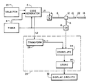
- For a better understanding of the invention, and to show how the same may be carried into effect, reference will now be made, by way of example, to the accompanying drawing which illustrates a simplified block diagram of an FOTDR embodying the present invention.
- The FOTDR shown in FIG. 1 comprises a
code generator 2 which generates an electrical signal, having a predetermined sequence of nbinary elements 1, 0, in response to a start pulse received from atimer 6 at time t=0. Each binary element is of duration te, and the entire sequence is of duration tp (= nte). For the sake of clarity, The invention will be described for the case for n=4, although in a practical implementation of the invention n would normally be much larger, and may be 1000 or more. The signal generated by thecode generator 2 is applied to anoptical source 4. Theoptical source 4, which includes a laser diode, responds to the sequence of binary elements by generating an optical signal having a duration tp. The power level of the optical signal at a given time within the interval tp depends upon the level of the electrical signal received from the code generator 2: if the electrical signal is atlevel 1, the optical pulse has a predetermined non-zero power level and if the electrical signal is at level 0 the optical pulse has a second power level. For the purpose of this description, the second power level will be assumed to be zero. - Optical energy emitted by the
source 4 is transmitted throughoptical fibers coupler 12 and is coupled into a fiber undertest 14 by way of itsproximal end face 22. A portion of the energy emitted into thetest fiber 14 is scattered back towards theproximal end face 22 and is transmitted through thefibers coupler 12, and afiber 16 to anoptical detector 18, e.g., a photodiode. Thedetector 18 generates an electrical output signal of which the voltage is related in substantially linear fashion to the power incident on the detector. This electrical output signal is applied to asignal processing circuit 24. - At time T, the
timer 6 causes thecode generator 2 to generate a signal, containing the same sequence of binary elements as the signal applied to thesource 4, and apply this signal to theprocessing circuit 24. Thesignal processing circuit 24 includes atransformation block 26 which receives the sequence of 1's and 0's from the code generator and generates a derivative sequence in response thereto. Preferably, the derivative sequence generated by thetransformation block 26 in response to the sequence of 1's and 0's generated by thecode generator 2 is a sequence of +1's and -1's, such that for every 1 in the sequence generated by thecode generator 2 the transformation block generates a +1 and for every 0 generated by thecode generator 2 the transformation block generates a -1. The two signals received from thetransformation block 26 and thedetector 18 are correlated in acorrelation block 28. - The
code generator 2 is programmed so that the sequence of binary elements that it generates in response to the start pulse is one of four possible sequences, and acode selector 20 is connected to thecode generator 2 to select which sequence of the four is to be generated. The four sequences that are generated by thecode generator 2 are two Golay complementary sequences and their logical complements. For each value of T, the operation of generating the selected sequence, energizing thesource 4, and correlating the output signal of thedetector 18 with the output signal of thetransformation block 26 are carried out four times, using the four sequences respectively. As each correlation is performed, the result of the correlation, which is the correlation function for the output signal of thedetector 18 and the output signal of the transformation block for that value of T, is written into amemory 30, and when all four correlations have been performed the sum of all four correlation functions is formed and is provided to thedisplay circuits 32 of the FOTDR. It is of course possible to carry out more than one correlation between launching consecutive optical signals into thefiber 14, provided that the duration of the electrical signal generated by thecode generator 2 is less than the time taken for the optical signal to travel from thesource 4 to the distal end of the fiber and back to thedetector 18. - If the Golay complementary sequences of 1's and 0's generated by the
code generator 2 are represented by A and B respectively, and their logical complements by Aʹ and Bʹ, then the optical power incident upon the photodetector due to light scattered from a given location in thefiber 14 will be proportional to the sequences A, B, Aʹ and Bʹ. The sequences of +1's and -1's generated by the transformation block in response to the sequences A, B, Aʹ and Bʹ of 1's and 0's received from the code generator may be represented by a, b, aʹ and bʹ respectively. It will be seen that
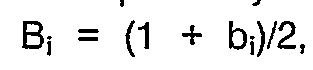


where * represents correlation and 1 represents a sequence of the same length as A and B but having all 1's. It follows from equations (1) and (2) that the sum of the correlation functions is equal to zero for T ≠ τ and is equal to 2n for T = τ. Accordingly, by transmitting not only the Golay complementary optical codes A and B but also their logical complements Aʹ and Bʹ, and correlating the optical codes with their counterpart codes of +1's and -1's, correlation functions with zero sidelobes are obtained. - Tables 1 and 2 illustrate by way of example the results that are obtained when the optical signals that are launched into the
fiber 14 are encoded in accordance with a pair of four-term Golay complementary sequences (1000 and 0010) and their logical complements (0111 and 1101). In Table 1, the left side represents the power transmitted into the test fiber by thesource 4, and received from the fiber by thedetector 18 due to scattering within the test fiber. The right side of Table 1 illustrates the codes with which the signals representing the level of received optical power are respectively correlated. The upper four rows of Table 2 illustrate the correlation functions yielded by the correlations indicated in Table 1 for different values of T in the range from

processing circuit 24 will not be equal to 2n for T = τ but will be reduced due to attenuation in the fiber. However, the correlation functions still have zero sidelobes.
- The detector is a substantially linear device over its range of operation, and this enables the processing circuit to discriminate between energy reflected from two locations that are spaced apart in the fiber by a distance less than vtp, provided that the distance is greater than vte, even though receipt of energy from one location overlaps receipt of energy from the other location. Computer simulation indicates that substantial deviations from linear performance on the part of the detector can be tolerated.
- Although for the sake of clarity the invention has been described in terms of discrete power levels occuring in well-defined intervals, it will be understood that the level of power received by the
detector 18 from the fiber will not fall neatly into discrete levels, because of attenuation in the fiber, scattering, and reflections from multiple discontinuities. Therefore, instead of correlating by summing the products of two sequences of clearly-defined values, correlation would in fact be performed by integrating the multiplication product of two time-dependent functions. The resulting sum of correlation functions has zero sidelobes. - It will be appreciated that the present invention is not restricted to the particular method and apparatus that have been described, and that variations may be made therein without departing from the scope of the invention as defined in the appended claims and equivalents thereof. For example, it is not essential that the sequences a, aʹ, b, bʹ be formed, since it can be shown that:


and therefore a function that has zero sidelobes can be achieved by transmitting the sequences A, Aʹ, B and Bʹ, correlating the returned power with the same sequences, adding the autocorrelation functions A*A and Aʹ*Aʹ, and subtracting the sum of the autocorrelation functions B*B and Bʹ*Bʹ. (Although not immediately apparent, this is equivalent to the multislit spectrometer experiment described by Golay.) Also, it is not necessary to transmit four sequences. Thus:


This last equation implies that a function having zero sidelobes can be generated by transmitting the sequence A and correlating the returned power with the sequence a, transmitting the sequence B and correlating the returned power with the sequence b, and transmitting thesequence 1 and correlating half of the returned power with a and half with b, adding the correlation sums A * a and B * b and then subtracting the sum of the correlation sums (1 * a)/2 and (1 * b)/2. - It can also be shown that


and therefore a function having zero sidelobes is generated by transmitting the sequence A and correlating the returned power with both a and 1, transmitting the sequence B and correlating the returned power with both b and 1, and transmitting thesequence 1 and correlating the returned power with 1. - The invention may be applied to transmission of information over a network by assigning a unique pair of Golay complementary sequences (and their logical complements) to each station. If, for example, the network has three stations P, Q and R and the Golay complementary sequences (and their logical complements) that are assigned to the stations respectively are designated p, q and r, the station P may communicate with the station Q by transmitting a message that is encoded using the sequences q. If, within a given clock period, the station Q receives the sequences q, this fact is interpreted by the station Q as a logical 1; if the station Q does not receive the sequences q, this fact is interpreted as a logical 0.
Claims (7)
- A method of carrying out a pulse-echo measurement on a medium (14) comprising:- applying a power pulse to the medium (14), the level at which the power pulse is applied varying as a function of time with sequences of elements where one kind of element is represented by a first power level and the other kind of element is represented by a second power level,- receiving an echo power pulse emitted from the medium (14) and- correlating the level of the echo power pulse with the level at which the power pulse was applied,
characterized in that
the level at which the power pulse is applied varies in accordance with the elements of at least two Golay complementary sequences where successive elements of each sequence are applied at uniform intervals. - A method according to claim 1, characterized in that the first and second power levels are each non-negative.
- A method according to claim 2, characterized in that the level at which the power pulse is emitted from the medium (14) is correlated with the level at which the power pulse is applied to the medium (14) by generating derivative Golay complementary sequences in which the two kinds of elements have a positive value and a negative value respectively, and the level at which the power pulse is emitted from the medium (14) is correlated with the derivative sequences.
- A method according to claim 1, characterized in that the medium is an optical fiber (14) having two opposite ends, and the method comprises applying an optical power pulse to the optical fiber (14) at one end thereof and receiving an optical echo power pulse emitted from the fiber (14) at said one end thereof.
- A method according to claim 4, characterized in that the first power level is positive and the second power level is zero, and the method comprises varying the level at which the power pulse is applied to the optical fiber (14) in accordance with the elements of first and second Golay complementary sequences and the logical complements of the first and second sequences, and the level at which the echo power pulse is emitted from the fiber (14) is correlated with the level at which the power pulse was applied to the fiber (14) by generating two derivative Golay complementary sequences, in which the two kinds of elements are of opposite respective polarities, from the first and second Golay complementary sequences respectively and also generating the logical complements of the two derivative Golay complementary sequences.
- Apparatus for carrying out a pulse-echo measurement on a medium (14) comprising
means (4) for applying a power pulse to the medium (14),
means (2) for varying the level at which the power pulse is applied to the medium (14) as a function of time in accordance with sequences of elements where one kind of element is represented by a first power level and the other kind of element is represented by a second power level, means (18) for receiving an echo power pulse emitted from the medium (14), and
means (24) for correlating the level of the echo power pulse with the level at which the power pulse was applied,
characterized in that
said level varying means (2) varies the level of the power pulse in accordance with the elements of at least two Golay complementary sequences where successive elements of each series are applied at uniform intervals. - A method of conveying information over a medium (14) comprising:
applying power to the medium (14), the level at which power is applied varying as a function of time in accordance with sequences of elements where one kind of element is represented by a first power level and the other kind of element is represented by a second power level, receiving power emitted from the medium and correlating the level at which power is emitted with the level at which power was applied,
characterized in that
the level at which the power is applied varies in accordance with the elements of at least two Golay complementary sequences where successive elements of each sequence are applied at uniform intervals.
Applications Claiming Priority (2)
| Application Number | Priority Date | Filing Date | Title |
|---|---|---|---|
| US06/903,916 US4743753A (en) | 1986-09-05 | 1986-09-05 | Method and apparatus for carrying out fiber optic time domain reflectomery wherein Golay complementary sequences are applied |
| US903916 | 1986-09-05 |
Publications (3)
| Publication Number | Publication Date |
|---|---|
| EP0258843A2 EP0258843A2 (en) | 1988-03-09 |
| EP0258843A3 EP0258843A3 (en) | 1988-07-13 |
| EP0258843B1 true EP0258843B1 (en) | 1991-06-12 |
Family
ID=25418246
Family Applications (1)
| Application Number | Title | Priority Date | Filing Date |
|---|---|---|---|
| EP87112562A Expired EP0258843B1 (en) | 1986-09-05 | 1987-08-28 | Method and apparatus for carrying out pulse-echo measurement |
Country Status (4)
| Country | Link |
|---|---|
| US (1) | US4743753A (en) |
| EP (1) | EP0258843B1 (en) |
| JP (1) | JPS6367538A (en) |
| DE (1) | DE3770728D1 (en) |
Families Citing this family (17)
| Publication number | Priority date | Publication date | Assignee | Title |
|---|---|---|---|---|
| US5000568A (en) * | 1986-11-26 | 1991-03-19 | Hewlett-Packard Company | Spread spectrum optical time domain reflectometer |
| US4978863A (en) * | 1988-09-06 | 1990-12-18 | The Dow Chemical Company | Method and apparatus for fiber optic backscattered light measurement to determine flow rates of multi-phase streams |
| US5150717A (en) * | 1988-11-10 | 1992-09-29 | Arye Rosen | Microwave aided balloon angioplasty with guide filament |
| DE68907886T2 (en) * | 1989-01-24 | 1994-01-13 | Hewlett Packard Gmbh | Method and device for using optical time domain reflectometers. |
| US4952057A (en) * | 1989-05-03 | 1990-08-28 | The United States Of America As Represented By The Secretary Of The Navy | Optical fiber backscatter signature generator (OFBSG) |
| DE8909905U1 (en) * | 1989-08-18 | 1989-09-28 | ANT Nachrichtentechnik GmbH, 7150 Backnang | Backscatter meter |
| US5069544A (en) * | 1990-04-12 | 1991-12-03 | Minnesota Mining And Manufacturing Company | Adaptive pulse width optical fault finder |
| US5066118A (en) * | 1990-04-12 | 1991-11-19 | Minnesota Mining And Manufacturing Company | Optical fault finder using matched and clipping filters |
| US5482862A (en) * | 1991-04-04 | 1996-01-09 | The Dow Chemical Company | Methods for the on-line analysis of fluid streams |
| FR2678074B1 (en) * | 1991-06-18 | 1996-05-24 | Schlumberger Services Petrol | GEOPHYSICAL EXPLORATION PROCESS. |
| US5353110A (en) * | 1991-07-12 | 1994-10-04 | Tektronix, Inc. | Method and apparatus for carrying out optical time domain reflectometry using weighing techniques |
| FR2718587B1 (en) * | 1994-04-11 | 1996-05-03 | France Telecom | Optical reflectometry transmission-reception system. |
| DE4440434A1 (en) * | 1994-11-11 | 1996-05-30 | Siemens Ag | Method for operating an optical broadband connection line between an optical fiber connection unit and a passive optical interface |
| US6934655B2 (en) * | 2001-03-16 | 2005-08-23 | Mindspeed Technologies, Inc. | Method and apparatus for transmission line analysis |
| AU2003294419A1 (en) * | 2002-11-19 | 2004-06-15 | University Of Utah | Device and method for detecting anomolies in a wire and related sensing methods |
| US20100111217A1 (en) * | 2002-12-30 | 2010-05-06 | Fuente Vicente D | Method and system for reducing phase difference and doppler effects in detection and communication systems |
| US20180259422A1 (en) | 2017-03-10 | 2018-09-13 | Panduit Corp. | High Resolution Correlation Optical Time Domain Reflectometer |
Family Cites Families (3)
| Publication number | Priority date | Publication date | Assignee | Title |
|---|---|---|---|---|
| CA1044760A (en) * | 1974-10-09 | 1978-12-19 | Lim C. Hwa | Methods and equipment for testing reflection points of transmission lines |
| FR2505045A1 (en) * | 1981-04-30 | 1982-11-05 | Lignes Telegraph Telephon | Fibre=optic cable fracture location determn. circuit - uses clock to measure propagation time difference for two laser diodes emitting different wavelengths |
| FR2540314A1 (en) * | 1983-01-31 | 1984-08-03 | Trt Telecom Radio Electr | METHOD FOR INITIALIZING COEFFICIENT FILTERS IN A NEAR-AND-NEAR ECHO CANCELLATION DEVICE AND DEVICE FOR IMPLEMENTING SAID METHOD |
-
1986
- 1986-09-05 US US06/903,916 patent/US4743753A/en not_active Expired - Lifetime
-
1987
- 1987-08-28 DE DE8787112562T patent/DE3770728D1/en not_active Expired - Fee Related
- 1987-08-28 EP EP87112562A patent/EP0258843B1/en not_active Expired
- 1987-09-04 JP JP62221802A patent/JPS6367538A/en active Pending
Also Published As
| Publication number | Publication date |
|---|---|
| US4743753A (en) | 1988-05-10 |
| EP0258843A2 (en) | 1988-03-09 |
| EP0258843A3 (en) | 1988-07-13 |
| DE3770728D1 (en) | 1991-07-18 |
| JPS6367538A (en) | 1988-03-26 |
Similar Documents
| Publication | Publication Date | Title |
|---|---|---|
| US4743753A (en) | Method and apparatus for carrying out fiber optic time domain reflectomery wherein Golay complementary sequences are applied | |
| US5000568A (en) | Spread spectrum optical time domain reflectometer | |
| US5416623A (en) | Optical communications system | |
| JP6607934B2 (en) | Method and apparatus for measuring a physical value allocated to an optical device under test | |
| EP3460441B1 (en) | An optical channel monitoring system, and associated optical sensing system and optical sensing method | |
| US5353110A (en) | Method and apparatus for carrying out optical time domain reflectometry using weighing techniques | |
| US4159418A (en) | Delay line encoder-decoder | |
| US6850314B2 (en) | Method for optical sensing | |
| USH1626H (en) | Fiber optic network system with low crosstalk using code-division multiplexing | |
| SE8402647D0 (en) | OPTICAL DISTANCE SIMULATOR | |
| EP3994427A1 (en) | Interrogation of arrays of equally spaced weak reflectors in optical fibers | |
| EP0864081B1 (en) | Device for interrogating an optical fibre network | |
| EP1807686B1 (en) | Optical time domain reflectometry for determining distributed physical properties | |
| CA2005607C (en) | Method of analyzing guided optics components, optical fibres or optical guide networks by time reflectometry and reflectometer in the time sphere | |
| EP0269448A2 (en) | Optical time domain reflectometer | |
| JP2003115823A (en) | Reconfigurable multi-user optical communication network with low delay time | |
| EP0439551B1 (en) | Optical signal processor | |
| JP3210847B2 (en) | Optical pulse tester | |
| GB2581490A (en) | Method and device for measuring a pulse signal with high dynamic range | |
| Rao et al. | Spread spectrum technique for passive multiplexing of reflective frequency-out fibre optic sensors exhibiting identical characteristics | |
| CN113167677A (en) | Multi-layer encoding of optical signals | |
| JP2003329545A (en) | Optical fiber measuring apparatus | |
| JPH02134532A (en) | Method for processing backward scattered light in optical fiber | |
| Whitesel et al. | Code-division multiplexing of fiber optic sensors with LED sources | |
| EP0293441B1 (en) | Improvements relating to optical sensing systems |
Legal Events
| Date | Code | Title | Description |
|---|---|---|---|
| PUAI | Public reference made under article 153(3) epc to a published international application that has entered the european phase |
Free format text: ORIGINAL CODE: 0009012 |
|
| AK | Designated contracting states |
Kind code of ref document: A2 Designated state(s): DE FR GB NL |
|
| PUAL | Search report despatched |
Free format text: ORIGINAL CODE: 0009013 |
|
| AK | Designated contracting states |
Kind code of ref document: A3 Designated state(s): DE FR GB NL |
|
| 17P | Request for examination filed |
Effective date: 19880914 |
|
| 17Q | First examination report despatched |
Effective date: 19900508 |
|
| GRAA | (expected) grant |
Free format text: ORIGINAL CODE: 0009210 |
|
| AK | Designated contracting states |
Kind code of ref document: B1 Designated state(s): DE FR GB NL |
|
| PGFP | Annual fee paid to national office [announced via postgrant information from national office to epo] |
Ref country code: FR Payment date: 19910708 Year of fee payment: 5 |
|
| PGFP | Annual fee paid to national office [announced via postgrant information from national office to epo] |
Ref country code: GB Payment date: 19910712 Year of fee payment: 5 |
|
| REF | Corresponds to: |
Ref document number: 3770728 Country of ref document: DE Date of ref document: 19910718 |
|
| ET | Fr: translation filed | ||
| PGFP | Annual fee paid to national office [announced via postgrant information from national office to epo] |
Ref country code: DE Payment date: 19910729 Year of fee payment: 5 |
|
| PGFP | Annual fee paid to national office [announced via postgrant information from national office to epo] |
Ref country code: NL Payment date: 19910831 Year of fee payment: 5 |
|
| PLBE | No opposition filed within time limit |
Free format text: ORIGINAL CODE: 0009261 |
|
| 26N | No opposition filed | ||
| PG25 | Lapsed in a contracting state [announced via postgrant information from national office to epo] |
Ref country code: GB Effective date: 19920828 |
|
| PG25 | Lapsed in a contracting state [announced via postgrant information from national office to epo] |
Ref country code: NL Effective date: 19930301 |
|
| NLV4 | Nl: lapsed or anulled due to non-payment of the annual fee | ||
| GBPC | Gb: european patent ceased through non-payment of renewal fee |
Effective date: 19920828 |
|
| PG25 | Lapsed in a contracting state [announced via postgrant information from national office to epo] |
Ref country code: FR Effective date: 19930430 |
|
| PG25 | Lapsed in a contracting state [announced via postgrant information from national office to epo] |
Ref country code: DE Effective date: 19930501 |
|
| REG | Reference to a national code |
Ref country code: FR Ref legal event code: ST |