EP0256859B1 - Document dispenser - Google Patents
Document dispenser Download PDFInfo
- Publication number
- EP0256859B1 EP0256859B1 EP87307170A EP87307170A EP0256859B1 EP 0256859 B1 EP0256859 B1 EP 0256859B1 EP 87307170 A EP87307170 A EP 87307170A EP 87307170 A EP87307170 A EP 87307170A EP 0256859 B1 EP0256859 B1 EP 0256859B1
- Authority
- EP
- European Patent Office
- Prior art keywords
- document
- documents
- feeding
- module
- stacker
- Prior art date
- Legal status (The legal status is an assumption and is not a legal conclusion. Google has not performed a legal analysis and makes no representation as to the accuracy of the status listed.)
- Expired - Lifetime
Links
- 230000007246 mechanism Effects 0.000 claims description 50
- 230000001133 acceleration Effects 0.000 claims description 47
- 238000000926 separation method Methods 0.000 claims description 2
- 238000010276 construction Methods 0.000 description 6
- 229920001971 elastomer Polymers 0.000 description 2
- 229920004943 Delrin® Polymers 0.000 description 1
- 230000005540 biological transmission Effects 0.000 description 1
- 150000001875 compounds Chemical class 0.000 description 1
- 230000001186 cumulative effect Effects 0.000 description 1
- 230000009977 dual effect Effects 0.000 description 1
- 230000000694 effects Effects 0.000 description 1
- 239000000806 elastomer Substances 0.000 description 1
- 230000000977 initiatory effect Effects 0.000 description 1
- 238000004519 manufacturing process Methods 0.000 description 1
- 239000000463 material Substances 0.000 description 1
- 125000006850 spacer group Chemical group 0.000 description 1
Images



Classifications
-
- B—PERFORMING OPERATIONS; TRANSPORTING
- B65—CONVEYING; PACKING; STORING; HANDLING THIN OR FILAMENTARY MATERIAL
- B65H—HANDLING THIN OR FILAMENTARY MATERIAL, e.g. SHEETS, WEBS, CABLES
- B65H3/00—Separating articles from piles
- B65H3/44—Simultaneously, alternately, or selectively separating articles from two or more piles
-
- B—PERFORMING OPERATIONS; TRANSPORTING
- B65—CONVEYING; PACKING; STORING; HANDLING THIN OR FILAMENTARY MATERIAL
- B65H—HANDLING THIN OR FILAMENTARY MATERIAL, e.g. SHEETS, WEBS, CABLES
- B65H39/00—Associating, collating, or gathering articles or webs
- B65H39/02—Associating,collating or gathering articles from several sources
- B65H39/04—Associating,collating or gathering articles from several sources from piles
- B65H39/043—Associating,collating or gathering articles from several sources from piles the piles being disposed in juxtaposed carriers
-
- B—PERFORMING OPERATIONS; TRANSPORTING
- B65—CONVEYING; PACKING; STORING; HANDLING THIN OR FILAMENTARY MATERIAL
- B65H—HANDLING THIN OR FILAMENTARY MATERIAL, e.g. SHEETS, WEBS, CABLES
- B65H2701/00—Handled material; Storage means
- B65H2701/10—Handled articles or webs
- B65H2701/19—Specific article or web
- B65H2701/1912—Banknotes, bills and cheques or the like
Definitions
- a document dispenser of the kind disclosed in FR-A-2,418,501 is according to the invention characterised in that each bin is located in an individual module having its own separate frame which also supports the document feeding and separating apparatus for that bin and the common feed path extends through the modules in series and in that the document feeding and separating apparatus in each module includes document acceleration means for providing a space between the successively fed documents, and document delivery means for feeding the spaced apart documents along the feed path.
- the document dispenser disclosed in Figures 1-8 is a perferred embodiment of the invention and that various changes may be made in the construction and arrangement of parts without departing from the scope of the invention as defined by the appended claims.
- the document dispenser may be hooked up to be operated either by one or two tellers.
- the stacker is shown in Figures 1-8 as being part of a feeder/stacker module, the stacker could be incorporated in a separate module and all the other hopper/feeder modules could be of the same construction including a document bin and a document feeding means as described above.
Landscapes
- Engineering & Computer Science (AREA)
- Mechanical Engineering (AREA)
- Sheets, Magazines, And Separation Thereof (AREA)
- Collation Of Sheets And Webs (AREA)
Description
- This invention relates to document dispensers of the type wherein documents are dispensed from a plurality of separate stacks of documents contained in bins. The document dispenser of the invention is particularly useful for holding and dispensing paper currency on demand from a bank teller and serves to augment or replace a bank teller's cash drawer.
- FR-A-2,418,501 discloses a document dispenser for dispensing documents from a plurality of stacks of documents, comprising a plurality of bins for holding respective stacks of documents, and document feeding and separating apparatus associated with each bin for selectively feeding documents from the bins along an initial path portion into a common feed path to a delivery portion leading into a stacker.
- A similar document dispenser is disclosed in
WO 86/04567 published after the priority date of the present application. - Other prior art devices are disclosed in US Patent Nos. 4,253,651 and 4,500,084.
- A document dispenser of the kind disclosed in FR-A-2,418,501 is according to the invention characterised in that each bin is located in an individual module having its own separate frame which also supports the document feeding and separating apparatus for that bin and the common feed path extends through the modules in series and in that the document feeding and separating apparatus in each module includes document acceleration means for providing a space between the successively fed documents, and document delivery means for feeding the spaced apart documents along the feed path.
- The prior art document dispensers of the type which can be manufactured to operate with different numbers of separate bins are expensive and involve complex document feed paths. The document dispensers of the prior art involve a separate construction for two bin, three bin, four bin, five bin, or six bin models with an associated unique conveyer design for the document feed path in each of the models. Accordingly, each model is substantially different from a model having a different number of bins thereby resulting in excessive costs in manufacture and design.
- A typical preferred embodiment of the invention is constructed of modules so that different product models involving different numbers of bins, typically from two to six bins, can be constructed by interconnecting various numbers of standard modules thereby reducing the costs of each model substantially. The dispenser is constructed by assembling the modules, one for each bin, with each module including an input hopper (bin) and a document feeder. The modules are connected together to feed the documents along a common delivery feed path to a stacker which, in the preferred design, is provided on a special feeder/stacker module on the dispensing end of the device. Alternatively, the stacker could be a separate module, and all the hopper/feeder modules have the same construction. The design is such that in order to meet the requirements of two, three, four, five or six bin devices, a like number of modules are interconnected to form the dispenser model. Each dispenser model is fully constructed at the factory where the modules can be interconnected in the appropriate number and combination.
- More specifically, the preferred document dispenser includes a feeder/stacker module which includes a bin for holding a first stack of documents, a stacker for receiving successively fed documents and stacking them, and means for feeding the documents from the first stack through a first document feed path to the stacker means. The document feeding means includes document feeding and separating apparatus for feeding documents from the first stack so they move individually successively through the initial portion of the first document feed path, document acceleration means for providing a space between the successively fed documents, and document delivery means for feeding the spaced apart documents through a delivery portion of the first document feed path to the stacker means. The document acceleration means and the document delivery means use a common drive component, ie., an acceleration roller means. The document dispenser also includes at least one further module which has a bin for holding a second stack of documents and means for feeding the documents from the second stack through a second document feed path. The document feeding means of the further module is similar to that of the feeder/stacker module and includes document feeding and separating apparatus for feeding documents from the second stack individually in a successive condition through the initial portion of the second document feed path, document acceleration means providing a space between the successively fed documents, and document delivery means for feeding the spaced apart documents through a delivery portion of the second document feed path into the entrance of the delivery portion of the first document feed path of the feeder/stacker module so that the documents passing from the delivery portion of the second feed path pass into the delivery portion of the first document feed path and to the stacker means.
- Figure 1 is a perspective view showing the document dispenser in accordance with the invention arranged to be controlled by two bank tellers.
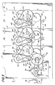
- Figure 2 is an elevational view looking toward the side of the dispenser where the document feeding mechanism of the modules is located.
- Figure 3 is an elevational view of the document dispenser looking from the side thereof where the drive means for the document feeding mechanism is provided.
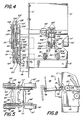
- Figure 4 is an elevational view looking from the back end of Figure 2.
- Figure 5 is a plan view of a detail.
- Figure 6 is a perspective view of a feeder module in preparation for mounting on the dispenser.
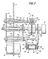
- Figure 7 is an elevational view showing the bearing mounting arrangement for the various feed rollers employed in the feeding mechanism of the document dispenser in accordance with the invention.
- Figure 8 is a detail view showing part of the stacker means.
- Figure 1 illustrates a document dispenser in accordance with the invention arranged to be controlled by two bank tellers by the use of the
computer control devices cabinet 3 provided with a door that can be locked with the same security as a typical cash drawer. Thecontrol devices - In Figures 2 and 3, the
cabinet 3 has been omitted so as to illustrate the mechanism in accordance with the invention for a model comprising three bins. The dispenser shown in the drawings comprises a feeder/stacker module 10 which has a frame which is mounted on a base contained in thecabinet 3 by suitable means (not shown) and includes a vertically extending side plate 11 and asecond plate 12 mounted in spaced apart parallel relation to the side plate 11 for supporting the various drive and bearing mechanisms of the dispenser as will be described hereafter. On the document handling side of plate 11, extending transversely therefrom, are twoguide plates shelf 15 extending generally horizontally, although inclined downwardly as is apparent in Figure 2. The upper portions ofplates shelf 15 cooperate to define a generally vertically extendingbin 16 for receiving a first stack of documents, which stack is inclined to the vertical so as to cause the documents placed in thebin 16 to have the bottom group of documents inclined toward the direction of feed as will be described hereafter. The stack of documents placed on theshelf 15 of thebin 16 rest against the upper portion ofplate 14 which provides a back plane. By this arrangement, the bottommost document is fed through anopening 17 into the nip of the document feeding and separating apparatus as will be described hereafter. Abottom guide plate 18 is also mounted on the side plate 11 to extend transversely therefrom and, in cooperation with the bottom portion ofguide plate 13, to define the guide path for feeding the documents from a document delivery means to the stacker mechanism as will be described hereafter. Also the lower portions ofplates - As is shown in Figure 2, the
bin 16 in which the first stack of documents is held consists of asupport shelf 15 inclined slightly downwardly from the horizontal towards the back plane and toward the feed path so as to aid the movement of the documents into the feed path. The bottom group of documents in a stack inbin 16 have their movement limited toward the feed path by the portion ofplate 14 which is bent slightly in the direction of the document feed and is spaced from the end portion ofsupport shelf 15 to define a throat for the feed of the documents into the feed path. - As discussed above, the bottommost document of the stack is fed through an
opening 17 into the nip of a document feeding and separating apparatus which functions to feed single documents successively along the document feed path, which apparatus is the same as that described in detail in U.S. Patent No. 4,500,084. This apparatus includes a stripper mechanism which operates to prevent more than one document from passing through the feed path at a time and maintains a continuous feed of the documents. - The document feeding and separating apparatus comprises a
shaft 24 which supports a pair of friction drums orrolls Shaft 24 is mounted on the dispenser frame bybearings plates 11 and 12 to be rotated about its longitudinal axis.Friction drums shaft 24 to rotate together and have high friction tread portions formed at their end portions adjacent to anidler pulley 26 therebetween with the treads being evenly spaced and parallel to the drum axis and the treads of one drum being offset from those of the other as is best shown in Figure 6. Thedrums shaft 24 which is occupied by the free-wheeling idler 26, the so called non-friction belt deflection member. Aknob 27 is secured onshaft 24 for manual rotation thereof. As is best shown in Figure 7, a pair ofrollers 29 are mounted onshaft 24 to help feed the documents. - A
stripper mechanism 28 comprisesstripping friction belt 30 of an elastomeric compound having a cross-section to avoid conforming to the shape of the face of theidler pulley 26 and to minimize forces acting on the document passing thedrums Friction belt 30 is shown supported at one end on adrive pulley 32 having a rubber friction surface at its outer periphery. Pulley 32 is mounted on adrive shaft 34 rotatably supported onplates 11 and 12 of the frame bybearings drums pulley 32 is fixed to thedrive shaft 34 which is driven by drive means to be described hereafter and which in turn drives thefriction belt 30.Shafts drums belt 30, the parts moving in the direction as shown by the arrows in Figure 2. -
Friction belt 30 is supported at its other end by anidler pulley 36 which is supported on ashaft 38. Pulley 36 is supported on abracket 42 on theguide plate 14 forming the back plane which is provided with suitable slots to permit passage of thebelt 30 and support structure where necessary. - The supporting structure for
shaft 38 including thebracket 42 is constructed to provide for adjustment ofpulley 36 in a manner and for a purpose described more fully in Patent No. 4,500,084. Briefly, supportingbracket 42 is part of an angular bracket which is supported by fasteners which enable the device to be moved under a leaverage force to permit the fine tensioning adjustment of thebelt 30. - Another
pulley 54, the so-called third rotatable means, is rotatably supported on ashaft 56 for rotatable movement in a free-wheeling way. Pulley 54 may be made of a moldable plastic such as "Delrin". Pulley 54 is provided with enlargeddiameter rim portions 54a and 54b which are spaced apart sufficiently to give a wide clearance for thebelt 30 so that each rides on a smooth portion of the surface offriction drums belt 30 in the slack belt condition when no document is passing through the feed path, i.e., pulley preferably does not apply to tension to thebelt 30 in the position where there is no document passing through the nip ofbelt 30 and the friction drums 22A and 22B. -
Shaft 56 ofpulley 54 is supported on an arm ofbracket 58 which, in turn, is pivotally supported onshaft 34. The support structure is of such length as to position thepulley 54 in the vicinity of the midpoint of the wraparound offriction belt 30 onpulley 26 intermediate thedrums brtacket 58 is movable so thatrim portions 54a and 54b can move into contact with the friction surfaces ofdrums idler pulley 54 to move away from the drums as a document passes through.Pulley 54 is of such a diameter that itcontacts friction belt 30 at its outside, remote from the friction drums 22A and 22B only slightly, if at all, in the slack condition of thebelt 30 when no documents are passing through. - As is described in said Patent No. 4,500,084, when a document passes between the
belt 30 andfriction drums pulley 54 is moved outwardly against thebelt 30 producing tension onbelt 30 at that point, thereby causing a stripping effect acting to separate documents to be increased. Thepulley 54 functions to change the tension onbelt 30 automatically to handle various documents of various flexibilities as is described in said patent. - The stripper mechanism comprises a pair of
stripper idlers 60 each of which is mounted for free-wheeling rotation onstripper shaft 34 by means of a centrally locatedjournal 62 thereof.Pulley 32 forstripper belt 30 is located centrally betweenstripper idlers 60 which are spaced axially therefrom by spacers as shown in Figure 7. -
Stripper idlers 60 are identical in construction but are mounted onshaft 34 to face in opposite direction as best shown in Figure 4, each stripper idler 60 having a tubular hub which is secured onto a journal with a pressed fit.Stripper idlers 60 are made of a high friction elastomer and have a generally shallow cup-shaped configuration. The geometry of eahc stripper idler 60 is such that the resiliency thereof will maintain the proper force or pressure against the feed roller means provided bydrums stripper idlers 60 are flexible away from the feed roller means and are constructed and arranged such that when documents are present between the stripper idlers and the feed roller means, a desired pressure is applied to the documents that allows the bottom document to be fed in the desired direction through the apparatus by the feed roller means without creating an excessive force which tends to lock the bottom document by friction to the document thereabove. Thus,stripper idlers 60 assist in the separation of documents from a stack in the bin and assure the separating of adjacent documents in the feeding area. When no documents are present between the stripper idler 60 anddrums stripper idlers 60 are driven bydrums stripper shaft 30 on a free-wheeling manner.Drums stripper belt 30 are driven in the counter-rotating manner as shown by the arrows in Figure 2 and as described in said patent. When a stack of documents is placed in thebin 16, they are driven towards thestripper idlers 60 by picker rollers 19 (to be described hereafter). The bottom document in the stack is urged into the nip of thedrums counter-rotating stripper belt 30. When a document passes between thestripper idlers 60 anddrums Drums stripper idlers 60 and operate to feed the bottom documents through the feeding area.Stripper idlers 60 will slow down to approximately the speed of the documents receiving in thebin 16 as the bottom document is fed through the apparatus bydrums - By the above-described feed means, single documents are fed successively in edge-to-edge contact around the feed roller means and are guided vertically downwardly by the vertically extending portion of the
guide plate 14. A pair ofidler rollers 64a, 64b are mounted onleaf springs drums idler rollers 64a, 64b anddrums guide plate 14. - Means are provided for providing a space between the successively fed documents so as to permit counting thereof. Such means comprises a pair of
acceleration rollers 66 mounted on ashaft 68 extending horizontally from the side plate 11 and in parallel relation toshafts Shaft 68 is rotatably mounted in bearing means 67, 69 mounted onplates 11, 12 as best shown in Figure 7. Each of theacceleration rollers 66 has associated therewith anidler roller 70 mounted, by brackets on the lower end ofplate 14, to rotate in contact with the surface ofroller 66 as best shown in Figures 2 and 4. The documents being fed vertically downwardly from the feed and stripper mechanism pass into the nip of theacceleration rollers 66 and their associatedidler rollers 70. Theacceleration rollers 66 are driven to rotate at a high speed (about 2.5 times the linear speed ofdrums acceleration rollers 66 and their associatedidler rollers 70 where the high friction of the acceleration roller effectively pulls each document away from the feeder/stripper mechanism. Thus, for a time, the preceding document is moving faster than the following document in order to create a space between sequential documents to facilitate the detecting and counting of the individual documents. - There is provided a document sensing means including a
light emitting diode 72 and adetector 73 which sense the leading edge of each document as it passes a reference point in the document feed path at which time a signal is sent to document counting control which records the signal and keeps a count of the documents being fed. The sensing position is preferably at the pinch of theacceleration rollers 66 and their associatedidler rollers 70 as is shown in Figure 2. - The feeder/
stacker module 10 is provided with a document delivery means for feeding the spaced apart documents moving around theacceleration rollers 66 through a delivery portion of the document feed path on said module to a stacker means indicated generally at 90. Such means comprises theacceleration rollers 66 and anidler mechanism 76 associated therewith. Theidler mechanism 76 comprises a pair ofbelts 77, each being mounted on a pair of spaced apart pulleys 78 and 79, the parts being mounted on the underside ofplate 18 by a bracket arrangement to be described more fully hereafter. Theidler mechanism 76 is mounted at a location beneath its associatedacceleration rollers 66 such that thebelts 77 thereof are urged into contact with the documents passing under the lower portion ofacceleration rollers 66. Theidler mechanism 76 includes a pair ofrollers 80 formed by circular rims mounted on each of thepulleys 78 to the outside ofbelts 77, the mechanism being mounted so that oneroller 80 is urged into contact with one of the acceleration rollers at the lower portion thereof. - The
idler mechanism 76 cooperates with theacceleration rollers 66 to receive downwardly moving spaced apart documents and deliver them in a generally horizontal direction along the upper surface ofguide plate 18 into engagement with thefingers 92 of aconventional stacker wheel 91 of the stacker means 90. To this end, the lower end ofguide plate 14 is bent forwardly to guide the leading edge of the downwardly moving documents into the nip of theacceleration rollers 66 and the associatedroller 80 of theidler mechanism 76 as shown in Figure 2. - It is noted that the
acceleration rollers 66 are utilized to perform dual functions. First, theacceleration rollers 66 cooperate with theidler rollers 70 to achieve the spacing apart of the documents as described above. Secondly, theacceleration rollers 66 cooperate with therollers 80 of theidler mechanism 76 to assist in the delivery of the documents along a generally horizontal path to the stacker means 90. - The stacker means 90 is conventional and comprises a
stacker wheel 91 and a plurality (ten) offingers 93 which function in a conventional manner to deliver the documents into a dispenser tray 93 (see Figure 1) whereby they can be removed by the operator on the completion of a dispensing operation. - The feeder/
stacker module 10 is provided with a second document sensing means including a light emitting diode 94 and adetector 95 which sense the leading edge of each document as it passes between theacceleration rollers 66 and thebelts 77 of their associatedidler mechanisms 76. As each document successively passes between the diode 94 anddetector 95, in the document delivery feed path, a signal is sent to a document counting control which records the signal and keeps count of the documents being fed to the stacker means 90. - The
stacker 90 also includes a light emitting diode (LED) 98 and a sensor ordetector 99 located such that any document which has been stacked in thetray 93 will break the transmission of light from theLED 98 to thesensor 99. Accordingly, the presence of documents intray 93 is detected by thesensor 99 and, in an actual embodiment of the invention this information is used by the control means for the document dispenser in three ways: - (1) a second dispense cannot be made until the operator removes the documents from the first dispense.
- (2) The
stacker 90 is designed to hold a limited number of documents, ie., N documents. When N documents are dispensed, the until will stop, even if more documents are to be dispensed. When the operator removes the N documents in thetray 93, this is detected and the dispensing of the remainder of the documents to be dispensed can proceed. - (3) The dispenser is designed so that two tellers can operate the unit. When one of these two operators has completed a dispense but has not removed the documents from the
tray 93, the other teller is prevented from using the dispenser. When the documents are removed from thetray 93, this is detected by the LED/sensor means whereupon the other teller is permitted to proceed with the dispensing. - The drive system for the document feeding means described above is shown in Figures 3 and 4. The drive system comprises a pair of electric motors M₁ and M₂. Motor M₁ is arranged to drive the
drive shafts acceleration rollers 66 and thestacker wheel 91. - Motor M₁ is mounted to extend through an opening in side plate 11 and is secured to plate 12 with its
drive shaft 100 extending outwardly, or to the left, ofplate 12 as viewed in Figure 4. Mounted ondrive shaft 100 of motor M₁ is adrive pulley 101 which drives asingle belt 102 which is arranged to engage and drive largesingle belt pulley 103 which is rotatably supported on apin 104 extending outwardly fromplate 12. A small diameterdouble belt pulley 105 is secured to the outer side of thesingle belt pulley 103 for rotation therewith. Thedouble belt pulley 105 is engaged with adouble belt 106 which is arranged to engage and drive a large diameterdouble belt pulley 107 secured on the outer end ofshaft 24 which drives the feed roller means. Inwardly of thelarge pulley 107,shaft 24 has formed thereon a small doublebelt pulley portion 108 which engages adouble belt 109 which extends upwardly to engage a large diameterdouble belt pulley 110 mounted on the end ofshaft 34 which drives the stripper mechanism. - By the above-described arrangement, motor M₁ drives the
shaft 24 for the feed roller means by way ofpulley 101,single belt 102,pulley 103,pulley 105,double belts 106 andpulley 107. The drive for thestripper mechanism shaft 34 is provided by thebelt 109 which interconnectsdouble pulley 108 onshaft 24 and thelarge pulley 110 onshaft 34. Means are provided for driving thepicker rollers 19 directly from theshaft 24. To this end,shaft 24 is provided with two small diameter signle pulley portions 111 which engage belts 112 which extend upwardly fromshaft 24 to engage pulleys on the picker rolls 19 (see Figures 2 and 7). - Motor M₂ is mounted on side plate 11 by means of a box-shaped
bracket 118 and has itsdrive shaft 120 extending outwardly of said bracket to carry asmall diameter pulley 121 thereon. Asingle belt 122 is engaged onpulley 121 and extends rearwardly therefrom to engage alarge diameter pulley 123 secured onshaft 68 which drives theacceleration rollers 66. - Means are provided for driving the
stacker wheel 91. to this end, the outer end ofshaft 68 extends beyond thedouble belt pulley 123 to form a small roller in contact with the surface of the rim of alarge diameter pulley 124 rotatably mounted on apin 119 mounted inplate 12 and extending transversely therefrom.Pin 119 has asmall diameter pulley 125 secured to the inside ofpulley 124 for rotation therewith.PUlley 125 is arranged to engage a forwardly extendingbelt 126 which engages asmall pulley 127 secured on the end of thedrive shaft 128 for thestacker wheel 91. By this arrangement, motor M₂ functions to drive thedrive shaft 68 for theacceleration rollers 66 as well as theshaft 128 driving thestacker wheel 91. - The
electrical lines 140 for supplying power to the motor M₁ are shown in Figure 3. Similarly, theelectrical lines 150 for the motor M₂ are shown in Figure 3. - As is best shown in Figures 2 and 6, the document dispenser comprises a
feeder module 160 positioned adjacent the feeder/stacker module 10. Thefeeder module 160 is very similar in construction and operation to the feeder/stacker module 10 whereby corresponding parts given the same reference numerals with primes added. The only essential difference between the feeder/stacker module 10 and thefeeder module 160 is that the former is provided with the stacker means 90 and the drive means therefor, otherwise, saidmodules - The
feeder module 160 is provided with a frame comprising a side plate 11ʹ and a plate 12ʹ. Side plate 11ʹ has mounted thereon a guide plate 14ʹ and a shelf 15ʹ extending in transverse relation therefrom and cooperating withwall 14 of feeder/stacker module 10 to define a bin 16ʹ for receiving a second stack of documents. There is also provided a pair of picker rollers 19ʹ at the bottom of bin 16ʹ for feeding the documents into the nip of the pair of feed rollers 22Aʹ, 22Bʹ and the cooperating stripper mechanism 28ʹ including a stripper belt 30ʹ and stripper idlers 60ʹ as described above with respect to the stacker/feeder module 10. Further, a pair of idler rollers 62aʹ, 64bʹ are mounted to cooperate with the feed rollers 22Aʹ, 22Bʹ to feed the separated documents individually vertically downwardly to the nip of a pair of acceleration rollers 66ʹ and their associated idler rollers 70ʹ. A delivery feed means includes an idler mechanism 76ʹ associated with each of the acceleration rollers 66ʹ and arranged to cooperate therewith for feeding the spaced apart documents in a horizontal feed path into the entrance of the delivery feed means of the adjacent feeder/stacker module 10. As shown in Figure 2, the idler mechanism 76ʹ cooperates with a pair of idler rollers 82ʹ mounted on a lower portion of plate 13ʹ by a bracket 75ʹ (see Figure 6) to cooperate with the forward portion of belts 77ʹ. Idler mechanism 76ʹ and rollers 82ʹ are constructed and arranged to feed the documents horizontally into the nip of theacceleration roller 66 and theiddler mechanism 76 of the feeder/stacker module 10. To this end, a pair of guide plates 13ʹ and 18ʹ have opposed portions arranged to extend horizontally and direct the documents in the desired direction as shown in Figure 2. - Figure 5 is a detail view showing idler mechanism 76ʹ used on
feeder module 160, as well as asecond feeder module 170 to be described hereafter. Idler mechanism 76ʹ is essentially the same asidler mechanism 76 as is shown in Figure 2. Referring to Figure 5, idler mechanism 76ʹ comprises a generally U-shaped mounting bracket 81ʹ, the base of which is secured to the underside of guide plate 18ʹ (see Figure 2), with the legs 84ʹ thereof extending vertically downwardly and forwardly therefrom. Another generally U-shaped bracket 83ʹ has its legs 85ʹ pivotally mounted on legs 84ʹ of bracket 81ʹ at pins 86ʹ. The forward ends of the pair of legs 84ʹ have the shafts 87ʹ of pulleys 79ʹ mounted thereon. The rearward ends of the pair of legs 85ʹ have the shafts 88ʹ of pulleys 78ʹ mounted thereon. The belts 77ʹ are made of a resilient stretchable material, idler mechanisms 76ʹ being mounted to place belts 77ʹ in a tensioned condition to provide a spring pressure against the acceleration rollers 66ʹ by rollers 80ʹ. - The drive means for the drive shafts 24ʹ and 34ʹ for the document feeding and separating mechanism of the
feeder module 160 comprises a motor M₁ʹ which is mounted on the plates 11ʹ and 12ʹ with its drive shaft 100ʹ extending out from plate 12ʹ and carrying a small pulley 101ʹ thereon. Pulley 101ʹ drives a belt 102ʹ which extends around a pulley 103ʹ rotatably carried on a pin 104ʹ mounted at the upper end of the plate 12ʹ. Pulley 103ʹ has secured thereto a small pulley 105ʹ which drives a belt 106ʹ thereon which also engages a large pulley 107ʹ keyed on the end of the drive shaft 24ʹ for driving the feed rollers 22Aʹ, 22Bʹ. Also mounted on shaft 24ʹ is a small pulley 108ʹ keyed on the drive shaft 34ʹ for the stripper mechanism 28ʹ as described above. - The motor M₁ʹ for the
feeder module 160 is powered through supply lines 140ʹ shown in Figure 3. - The drive means for drive shaft 68ʹ for acceleration rollers 66ʹ comprises the motor M₂ which drives shaft 68ʹ by means of a
belt 169.Belt 169 engages the outside portion of thedouble belt pulley 123 onshaft 68 and the outside portion of an identical double belt pulley 123ʹ secured on the end of shaft 68ʹ (see Figure 3). - As best shown in Figure 6, the
feeder module 160 is a complete modular unit and comprises all the document feed means necessary for feeding documents from a stack thereof to the adjacent feeder/stacker module 10. Thus, thefeeder module 160 is provided with its own stripper mechanism, its own feed roller mechanism, its own acceleration roller mechanism and its own delivery roller mechanism as discussed above. - In accordance with the invention, the
feeder module 160 and the feeder/stacker module 10 are provided with means for locating the two modules adjacent one another in a precise desired position, i.e., a position whereby the parts do not interfere with one another and the modules are as close as possible. To this end, the module frames are provided with overlapping locator portions provided with locator holes which are adapted to be aligned and to receive mounting screws for use in attaching thefeeder module 160 onto the feeder/stacker module 10 in the position as shown in Figures 2 and 3. - Thus, plate 11 of feeder/
stacker module 10 is provided with three locator holes A, B and C which are arranged to be aligned with locator holes a, b and c on plate 11 offeeder module 160, respectively, when the corresponding portions of plates 11 and 11ʹ are placed in an overlapping position. Mountingscrews module 160 is provided with a pair of locator holes d which are arranged to be aligned with corresponding locator holes inplate 14 ofmodule 10 with the overlapping portions of shelf 15ʹ andplate 14 being secured together by means of mountingscrews 164 extending through holes d. Further, a downwardly extending portion at the forward end of bottom plate 18ʹ ofmodule 160 is provided with a locator hole e which is adapted to be aligned with a corresponding locator hole in a downwardly extending portion at the back end ofplate 18 ofmodule 10, with the overlapping portions ofplates 18 and 18ʹ being secured together by mountingbolts 165 extending through hole e. Also, a pair of locator holes f are formed in the horizontally extending portion of plate 13ʹ ofmodule 160 and each is adapted to be aligned with a corresponding locator hole in the mounting bracket foridler roller 70 ofmodule 10 with the overlapping portions ofplate 13 and said bracket being secured together by means of mountingscrews 166 extending through holes f. -
Feeder module 160 is provided with a document sensing means including a light emitting diode 72ʹ and a detector 74ʹ which senses the leading edge of each document as it passes a reference point in the document feed path at which time it sends a signal to a document counting control which records the signal and keeps a count of the documents being fed. The sensing position is at the nip of the acceleration rollers 66ʹ and its associated idler 70ʹ as shown in Figure 2. - As is best shown in Figure 2, the document dispenser comprises a
second feeder module 170 positioned adjacent thefirst feeder module 160. Since thesecond feeder 170 module is identical to thefirst feeder module 160 corresponding parts have been given the same reference numbers. Thesecond feeder module 170 is provided with the same locator holes a-f which mate with the corresponding locator holes in thefirst feeder module 160 for use in positioning and mounting thesecond feeder module 170 adjacent thefirst feeder module 160 by mounting screws 161-166 as is best shown in Figure 2. - A
frame 180 is mounted on the back end of thesecond feeder module 170 to square off the back end of said module and provide a straight sided frame for use in mounting the dispenser's feeder mechanism within thecabinet 3 of the dispenser. - The
second feeder module 170 is provided with its own motor M₁ʹ for driving the shafts for the feed roller means, the stripper mechanism and the picker rollers, this drive means being identical to that described with respect to thefirst feeder module 160. Also, the drive shaft 68ʹ for the acceleration rollers 66ʹ of thesecond feeder module 170 is driven from motor M₂ by means of a double belt pulley 123ʹ mounted on the end of this shaft and driven by means of abelt 179 arranged to engage the inside portions of a double belt pulley 123ʹ formodule 170 and a similar pulley 123ʹ formodule 160 as is shown in Figure 3. - In use, the document dispenser shown in the drawings is adapted to dispense documents from three stacks of documents in the
bins 16, 16ʹ, 16ʹ of the feeder/stacker module 10 and the two feeder modules 160,170. By means of thecomputer control devices - In operation, documents from the first stack in
bin 16 ofmodule 10 will be fed initially and will move from said first stack through a first document feed path. The documents are fed from the first stack so they move individually in a successive condition through the initial portion of the first document feed path wherein the documents pass between the feed roller means and the stripper mechanism and downwardly toward theacceleration rollers 66. Theacceleration rollers 66 cooperate withidler rollers 70 to engage the succesively fed documents to provide a space therebetween and feed them to the entrance of the document delivery means including thedelivery idler mechanism 76 and the lower portions of theacceleration rollers 66 cooperating therewith. The documents pass from the entrance of the document delivery means horizontally through said means into the grip of thefingers 92 of thestacker wheels 91. - Next, the documents in the second bin 16ʹ of
module 160 are fed in the same manner as described above through a second document feed path with the spaced apart documents passing downwardly from the acceleration rollers 66ʹ and their associated idlers 70ʹ into the entrance of the document delivery means of themodule 160, said documents being delivered in a horizontal path by means of the acceleration rollers 66ʹ and the cooperating idler mechanism 76ʹ as described above. The documents pass horizontally from the document delivery means ofmodule 160 into the entrance of the document delivery means ofmodule 10 and pass therethrough into the grip offingers 92 ofstacker wheels 91. - In a like manner, the documents in the third stack in bin 16ʹ of
module 170 are fed individually in a successive condition through the initial portion of a third document feed path and downwardly to the acceleration rollers 66ʹ and idlers 70ʹ ofmodule 170 whereat they are separated and fed into the entrance of the document delivery means offeeder module 170, said documents being delivered in a horizontal path by means of the acceleration rollers 66ʹ and idler mechanism 76ʹ ofmodule 170. From this point, the documents pass horizontally from the document delivery means ofmodule 170 into the entrance of the document delivery means ofmodule 160 and pass therethrough and are delivered from themodule 160 into the entrance of the document delivery means ofmodule 10, namely,acceleration rollers 66 and the associatedidler mechanism 76, which operate to feed the documents to the stacker means 90 as described above. - It will be apparent that the document dispenser can be easily changed to provide additional bins for the feeding of additional stacks of documents. In actual practice, the dispenser will be available to provide anywhere from two to six bins by the addition of feeder modules in the manner described above.
- In the use of the document dispenser, the document sensing means 72, 73 or 72ʹ, 73ʹ for each of the modules is used to count the documents as well as to check for doubles or chains by the use of means as disclosed in U.S. Application No. 810,684, filed December 19, 1985. In addition, the provision of the document sensing means 94, 95 in the delivery feed portion of the feeder/
stacker module 10 permits a cumulative count for the documents as well as a redundant check for chains and doubles, again by the use of mechanism as disclosed in said application. - It will be apparent that the document dispenser can be easily constructed to meet the requirements for two, three, four, five or six bins, by providing a like number of
modules - Also the modular dispenser described herein can provide means for feeding, counting and stacking of documents with the initiation of these functions being provided by a two teller operation as shown in Figure 1. Moreover, each control device will contain some type of keyboard and control means to provide means for entering amounts of money to be dispensed, to control the other operations of the dispenser, and to provide accounting functions which are associated with the dispensing transactions. Further, the
control devices - It will be apparent that the document dispenser disclosed in Figures 1-8 is a perferred embodiment of the invention and that various changes may be made in the construction and arrangement of parts without departing from the scope of the invention as defined by the appended claims. For example, the document dispenser may be hooked up to be operated either by one or two tellers. Also, while the stacker is shown in Figures 1-8 as being part of a feeder/stacker module, the stacker could be incorporated in a separate module and all the other hopper/feeder modules could be of the same construction including a document bin and a document feeding means as described above.
Claims (7)
- A document dispenser for dispensing documents from a plurality of stacks of documents, comprising a plurality of bins (16,16') for holding respective stacks of documents, and document feeding and separating apparatus (19,22A,22B,54,60) associated with each bin for selectively feeding documents from the bins along an initial path portion into a common feed path to a delivery portion (18) leading into a stacker (90), characterised in that each bin (16,16') is located in an individual module (10,160,170, ...) having its own separate frame which also supports the document feeding and separating apparatus (19,22A,22B,54,60;19',22A',B',54',60') for that bin, and the common path extends through the modules in series and in that the document feeding and separating apparatus in each module includes document acceleration means (66,70) for providing a space between the successively fed documents, and document delivery means (76,80) for feeding the spaced apart documents along the feed path.
- A document dispenser according to claim 1, characterised in that the frames of the modules have locator holes (A,B,C ... a,b,c) to register with locator holes (a',b',c' ... A',B',C'...) of adjacent modules.
- A document dispenser according to claim 1 or 2, characterised in that the document acceleration means of each module includes an acceleration roller (66) and an idler roller (70) co-operating therewith for feeding and spacing the documents passing therebetween and an idler mechanism (76) co-operates with the acceleration roller (66) in the document feed path for feeding the spaced apart documents along the feed path.
- A document dispenser according to claim 3, characterised in that said idler mechanism includes a belt (77) extending along a substantially horizontal path of the lower end of said acceleration roller (66) for feeding the documents in a generally horizontal direction towards the stacker (90).
- A document dispenser according to any of the preceding claims, characterised in that the stacking means (90) and delivery portion (18) are located in a first module (10).
- A document dispenser according to any of the preceding claims, characterised by document sensing means (72,73) in each module located along said initial document feed path portion at a location to detect a document after separation from the bin.
- A document dispenser according to claim 6, characterised by further sensing means (94,95) located in the common feed path to detect a document as it is passing through said document delivery means (18) on the way to said stacker means.
Applications Claiming Priority (2)
| Application Number | Priority Date | Filing Date | Title |
|---|---|---|---|
| US896071 | 1986-08-13 | ||
| US06/896,071 US4691910A (en) | 1986-08-13 | 1986-08-13 | Document dispenser |
Publications (3)
| Publication Number | Publication Date |
|---|---|
| EP0256859A2 EP0256859A2 (en) | 1988-02-24 |
| EP0256859A3 EP0256859A3 (en) | 1989-01-18 |
| EP0256859B1 true EP0256859B1 (en) | 1993-03-10 |
Family
ID=25405579
Family Applications (1)
| Application Number | Title | Priority Date | Filing Date |
|---|---|---|---|
| EP87307170A Expired - Lifetime EP0256859B1 (en) | 1986-08-13 | 1987-08-13 | Document dispenser |
Country Status (4)
| Country | Link |
|---|---|
| US (1) | US4691910A (en) |
| EP (1) | EP0256859B1 (en) |
| JP (1) | JP2636252B2 (en) |
| DE (1) | DE3784588T2 (en) |
Families Citing this family (14)
| Publication number | Priority date | Publication date | Assignee | Title |
|---|---|---|---|---|
| US4903953A (en) * | 1988-04-20 | 1990-02-27 | Brandt, Inc. | Simplified currency dispenser |
| US4966357A (en) * | 1988-08-29 | 1990-10-30 | Brandt, Inc. | Apparatus for dispensing a preselected mix of paper currency or the like |
| EP0370484B1 (en) * | 1988-11-22 | 1994-07-27 | Canon Kabushiki Kaisha | Sheet feeding apparatus |
| US5074433A (en) * | 1989-12-04 | 1991-12-24 | Technitrol, Inc. | Document delivery and abort mechanism |
| US5164906A (en) * | 1990-11-20 | 1992-11-17 | Pitney Bowes Inc. | Submodule feeder arrangement for an inserter |
| EP0688298A4 (en) * | 1993-03-10 | 1996-07-10 | Technitrol Inc | Sorting feed mechanism |
| DE19536480C1 (en) * | 1995-09-29 | 1997-04-17 | Siemens Nixdorf Inf Syst | Drive for a device for dispensing sheet material, in particular notes of value |
| TW526335B (en) | 1998-11-12 | 2003-04-01 | Nippon Kouatsu Electric Co Ltd | Fault point location system |
| TW475991B (en) | 1998-12-28 | 2002-02-11 | Nippon Kouatsu Electric Co Ltd | Fault point location system |
| DE10046082A1 (en) * | 2000-09-15 | 2002-04-04 | Giesecke & Devrient Gmbh | Method and device for processing monetary units |
| US20020178130A1 (en) † | 2001-02-23 | 2002-11-28 | Christian Moy | Letter flow control |
| US7093831B2 (en) * | 2003-02-04 | 2006-08-22 | Palo Alto Research Center Inc. | Media path modules |
| CN1839081B (en) * | 2003-03-10 | 2010-09-15 | 迪布尔特有限公司 | Cash dispensing automated banking machine and method |
| CN112499310A (en) * | 2020-11-30 | 2021-03-16 | 重庆电子工程职业学院 | Teaching examination management system |
Family Cites Families (9)
| Publication number | Priority date | Publication date | Assignee | Title |
|---|---|---|---|---|
| JPS5841263B2 (en) * | 1978-02-28 | 1983-09-10 | ロ−レルバンクマシン株式会社 | Method for conveying banknotes in a banknote dispensing device |
| US4253651A (en) * | 1979-01-30 | 1981-03-03 | Technitrol, Inc. | Document interleaver device |
| SE8003705L (en) * | 1980-05-19 | 1981-11-20 | Leif Lundblad | DEFINITION OF SECURITIES AND OTHER DOCUMENTS |
| US4474365A (en) * | 1981-07-30 | 1984-10-02 | Brandt, Inc. | Document feeding, handling and counting apparatus |
| JPS5841263A (en) * | 1981-09-02 | 1983-03-10 | Hitachi Ltd | Electronic advance ignition system with pressure control |
| JPS58190772U (en) * | 1982-06-16 | 1983-12-19 | 株式会社東芝 | Deposit/withdrawal device |
| JPS606538A (en) * | 1983-06-22 | 1985-01-14 | Fuji Xerox Co Ltd | Paper feeder for option |
| US4500084A (en) * | 1983-07-27 | 1985-02-19 | Technitrol, Inc. | Stripper mechanism for document separating apparatus |
| US4660822A (en) * | 1985-02-07 | 1987-04-28 | Brandt, Inc. | Compact apparatus for dispensing a preselected mix of paper currency or the like |
-
1986
- 1986-08-13 US US06/896,071 patent/US4691910A/en not_active Expired - Lifetime
-
1987
- 1987-08-13 EP EP87307170A patent/EP0256859B1/en not_active Expired - Lifetime
- 1987-08-13 DE DE87307170T patent/DE3784588T2/en not_active Expired - Fee Related
- 1987-08-13 JP JP62202601A patent/JP2636252B2/en not_active Expired - Lifetime
Also Published As
| Publication number | Publication date |
|---|---|
| JP2636252B2 (en) | 1997-07-30 |
| US4691910A (en) | 1987-09-08 |
| EP0256859A2 (en) | 1988-02-24 |
| DE3784588D1 (en) | 1993-04-15 |
| DE3784588T2 (en) | 1993-10-14 |
| JPS6351274A (en) | 1988-03-04 |
| EP0256859A3 (en) | 1989-01-18 |
Similar Documents
| Publication | Publication Date | Title |
|---|---|---|
| US4691910A (en) | Document dispenser | |
| EP0616963B1 (en) | Sheet handling apparatus | |
| EP0499458B1 (en) | Sheet handling apparatus | |
| US3937453A (en) | Single document transport | |
| US4822018A (en) | Sheet handling apparatus | |
| US4684119A (en) | Sheet feeding apparatus | |
| US5335484A (en) | Sheet handling apparatus | |
| EP0216801B1 (en) | Compact apparatus for dispensing a preselected mix of paper currency or the like | |
| US4251010A (en) | Certificate dispenser | |
| US4936564A (en) | Sheet handling apparatus | |
| KR20000064328A (en) | Sheet take-out and tray | |
| US4482057A (en) | Record media dispensing apparatus | |
| EP0611718B1 (en) | Sheet stacking apparatus | |
| US5000088A (en) | Document imprinting device | |
| US6276603B1 (en) | Sheet dispensing mechanism | |
| CA1119627A (en) | Single-bill currency dispenser | |
| US5046713A (en) | Document imprinting device | |
| US4948115A (en) | Apparatus for dispensing a preselected mix of paper currency or the like | |
| JPH081232Y2 (en) | Feed roller pressure structure | |
| US5115739A (en) | Document imprinting device having a rotation detector mounted on the print drum | |
| JP2759194B2 (en) | Sheet handling equipment | |
| JP2590165B2 (en) | Paper processing equipment | |
| JPS6283934A (en) | Paper currency containing/dispensing device | |
| US20200342722A1 (en) | Straightforward Cash Dispenser | |
| JP2829399B2 (en) | How to remove jam paper from the sorter |
Legal Events
| Date | Code | Title | Description |
|---|---|---|---|
| PUAI | Public reference made under article 153(3) epc to a published international application that has entered the european phase |
Free format text: ORIGINAL CODE: 0009012 |
|
| AK | Designated contracting states |
Kind code of ref document: A2 Designated state(s): DE FR GB |
|
| PUAL | Search report despatched |
Free format text: ORIGINAL CODE: 0009013 |
|
| AK | Designated contracting states |
Kind code of ref document: A3 Designated state(s): DE FR GB |
|
| 17P | Request for examination filed |
Effective date: 19890321 |
|
| 17Q | First examination report despatched |
Effective date: 19901009 |
|
| GRAA | (expected) grant |
Free format text: ORIGINAL CODE: 0009210 |
|
| AK | Designated contracting states |
Kind code of ref document: B1 Designated state(s): DE FR GB |
|
| REF | Corresponds to: |
Ref document number: 3784588 Country of ref document: DE Date of ref document: 19930415 |
|
| ET | Fr: translation filed | ||
| PLBE | No opposition filed within time limit |
Free format text: ORIGINAL CODE: 0009261 |
|
| STAA | Information on the status of an ep patent application or granted ep patent |
Free format text: STATUS: NO OPPOSITION FILED WITHIN TIME LIMIT |
|
| 26N | No opposition filed | ||
| REG | Reference to a national code |
Ref country code: GB Ref legal event code: 732E |
|
| PGFP | Annual fee paid to national office [announced via postgrant information from national office to epo] |
Ref country code: GB Payment date: 20000703 Year of fee payment: 14 |
|
| PGFP | Annual fee paid to national office [announced via postgrant information from national office to epo] |
Ref country code: FR Payment date: 20000803 Year of fee payment: 14 |
|
| PGFP | Annual fee paid to national office [announced via postgrant information from national office to epo] |
Ref country code: DE Payment date: 20000830 Year of fee payment: 14 |
|
| PG25 | Lapsed in a contracting state [announced via postgrant information from national office to epo] |
Ref country code: GB Free format text: LAPSE BECAUSE OF NON-PAYMENT OF DUE FEES Effective date: 20010813 |
|
| GBPC | Gb: european patent ceased through non-payment of renewal fee |
Effective date: 20010813 |
|
| PG25 | Lapsed in a contracting state [announced via postgrant information from national office to epo] |
Ref country code: FR Free format text: LAPSE BECAUSE OF NON-PAYMENT OF DUE FEES Effective date: 20020430 |
|
| PG25 | Lapsed in a contracting state [announced via postgrant information from national office to epo] |
Ref country code: DE Free format text: LAPSE BECAUSE OF NON-PAYMENT OF DUE FEES Effective date: 20020501 |
|
| REG | Reference to a national code |
Ref country code: FR Ref legal event code: ST |