EP0256706B1 - Method and apparatus for equalizing power output in a laser marking system - Google Patents
Method and apparatus for equalizing power output in a laser marking system Download PDFInfo
- Publication number
- EP0256706B1 EP0256706B1 EP87306687A EP87306687A EP0256706B1 EP 0256706 B1 EP0256706 B1 EP 0256706B1 EP 87306687 A EP87306687 A EP 87306687A EP 87306687 A EP87306687 A EP 87306687A EP 0256706 B1 EP0256706 B1 EP 0256706B1
- Authority
- EP
- European Patent Office
- Prior art keywords
- laser
- lasers
- stroke
- marking
- ionization
- Prior art date
- Legal status (The legal status is an assumption and is not a legal conclusion. Google has not performed a legal analysis and makes no representation as to the accuracy of the status listed.)
- Expired - Lifetime
Links
Images


Classifications
-
- B—PERFORMING OPERATIONS; TRANSPORTING
- B23—MACHINE TOOLS; METAL-WORKING NOT OTHERWISE PROVIDED FOR
- B23K—SOLDERING OR UNSOLDERING; WELDING; CLADDING OR PLATING BY SOLDERING OR WELDING; CUTTING BY APPLYING HEAT LOCALLY, e.g. FLAME CUTTING; WORKING BY LASER BEAM
- B23K26/00—Working by laser beam, e.g. welding, cutting or boring
- B23K26/02—Positioning or observing the workpiece, e.g. with respect to the point of impact; Aligning, aiming or focusing the laser beam
- B23K26/06—Shaping the laser beam, e.g. by masks or multi-focusing
- B23K26/062—Shaping the laser beam, e.g. by masks or multi-focusing by direct control of the laser beam
- B23K26/0626—Energy control of the laser beam
-
- B—PERFORMING OPERATIONS; TRANSPORTING
- B23—MACHINE TOOLS; METAL-WORKING NOT OTHERWISE PROVIDED FOR
- B23K—SOLDERING OR UNSOLDERING; WELDING; CLADDING OR PLATING BY SOLDERING OR WELDING; CUTTING BY APPLYING HEAT LOCALLY, e.g. FLAME CUTTING; WORKING BY LASER BEAM
- B23K26/00—Working by laser beam, e.g. welding, cutting or boring
- B23K26/02—Positioning or observing the workpiece, e.g. with respect to the point of impact; Aligning, aiming or focusing the laser beam
- B23K26/06—Shaping the laser beam, e.g. by masks or multi-focusing
-
- B—PERFORMING OPERATIONS; TRANSPORTING
- B23—MACHINE TOOLS; METAL-WORKING NOT OTHERWISE PROVIDED FOR
- B23K—SOLDERING OR UNSOLDERING; WELDING; CLADDING OR PLATING BY SOLDERING OR WELDING; CUTTING BY APPLYING HEAT LOCALLY, e.g. FLAME CUTTING; WORKING BY LASER BEAM
- B23K26/00—Working by laser beam, e.g. welding, cutting or boring
- B23K26/02—Positioning or observing the workpiece, e.g. with respect to the point of impact; Aligning, aiming or focusing the laser beam
- B23K26/06—Shaping the laser beam, e.g. by masks or multi-focusing
- B23K26/0604—Shaping the laser beam, e.g. by masks or multi-focusing by a combination of beams
-
- B—PERFORMING OPERATIONS; TRANSPORTING
- B23—MACHINE TOOLS; METAL-WORKING NOT OTHERWISE PROVIDED FOR
- B23K—SOLDERING OR UNSOLDERING; WELDING; CLADDING OR PLATING BY SOLDERING OR WELDING; CUTTING BY APPLYING HEAT LOCALLY, e.g. FLAME CUTTING; WORKING BY LASER BEAM
- B23K26/00—Working by laser beam, e.g. welding, cutting or boring
- B23K26/02—Positioning or observing the workpiece, e.g. with respect to the point of impact; Aligning, aiming or focusing the laser beam
- B23K26/06—Shaping the laser beam, e.g. by masks or multi-focusing
- B23K26/0604—Shaping the laser beam, e.g. by masks or multi-focusing by a combination of beams
- B23K26/0613—Shaping the laser beam, e.g. by masks or multi-focusing by a combination of beams having a common axis
-
- G—PHYSICS
- G06—COMPUTING OR CALCULATING; COUNTING
- G06K—GRAPHICAL DATA READING; PRESENTATION OF DATA; RECORD CARRIERS; HANDLING RECORD CARRIERS
- G06K1/00—Methods or arrangements for marking the record carrier in digital fashion
- G06K1/12—Methods or arrangements for marking the record carrier in digital fashion otherwise than by punching
- G06K1/126—Methods or arrangements for marking the record carrier in digital fashion otherwise than by punching by photographic or thermographic registration
-
- B—PERFORMING OPERATIONS; TRANSPORTING
- B23—MACHINE TOOLS; METAL-WORKING NOT OTHERWISE PROVIDED FOR
- B23K—SOLDERING OR UNSOLDERING; WELDING; CLADDING OR PLATING BY SOLDERING OR WELDING; CUTTING BY APPLYING HEAT LOCALLY, e.g. FLAME CUTTING; WORKING BY LASER BEAM
- B23K2101/00—Articles made by soldering, welding or cutting
- B23K2101/007—Marks, e.g. trade marks
Definitions
- This invention relates to the field of marking devices for placing codes and the like on a substrate. More specifically, it relates to marking devices capable of placing alphanumeric codes, bar codes and other useful indicia on the surface of a product which moves relative to the marking device as, for example, on a conveyor. That device marks on objects moved past the laser beams.
- the present invention can be employed with a system which scans the beams across a stationary substrate, for example, using moving mirrors. Usually the marking is accomplished using a plurality of lasers having sufficient energy to permanently alter the surface of the product to be marked.
- One device with which the present invention may be employed is disclosed in European patent application EP-A-0 157 546 assigned to the present assignee which application is hereby incorporated by reference.
- Such a laser marking device employs a plurality of lasers, for example, seven.
- the output beam from each laser is sent through a beam delivery tube and a focusing lens onto the marking location.
- the seven beams are arranged by means of the lens to form a vertical column of seven beams, each capable of marking a dot onto the passing product.
- a dot matrix arrangement for printing alphanumeric characters is obtained in a manner well known in this art.
- By selectively turning on the lasers corresponding to the correct positions for a desired alphanumeric character such symbols may be marked onto the product.
- a 5 ⁇ 7 dot matrix is employed and thus, for each character to be printed, the seven lasers must be turned on and off five times in a sequence which will place dots where required to form the character.
- Each character is formed by turning on selected lasers simultaneously five separate times (each time being referred to as a stroke) as the substrate of the article to be marked moves past the laser lens.
- variations in laser energy output cause degradation of the print quality. Some dots are only partially formed or are missing entirely. Others are too large. This variation in laser output energy can result from: (1) variation in nominal laser output power, (2) turn on delay, (3) turn on and turn off time constants, (4) energy density and beam shape variation.
- a method and apparatus for compensating for variations in the luminance characteristics of light emitting diodes in a print head by varying the individual L.E.D. conduction times is know from JP-A-61 142 816.
- the present invention discloses a method and apparatus for equalizing laser output by controlling the electrical drive signals for each laser as specified in claims 1 and 8.
- the result substantially reduces the effect of laser performance variation on print quality.
- the control takes several forms. First, the relative energy output of each laser is determined and its on time is adjusted by appropriately weighting the on time of each laser relative to the weakest laser beam. Alternatively, the beam weighting can be relative to other references, such as average beam energy or even an independent reference value.
- the use of variable width "on" time pulses for the lasers can, however, introduce nonlinearity in the formed characters. To avoid or minimize this problem, all of the "on" pulses are centred about a selected time axis. Thus, the combination of weighted "on" pulses coupled with pulse centering provides a significant improvement in overall print quality.
- a further object of the invention is to provide a method and apparatus for varying the "on" pulse width of each laser in such a marking system to substantially equalize the energy outputs thereof.
- Another object of the invention is to provide a method and apparatus for centering the "on" pulses used to trigger the lasers to insure vertical linearity of the energy dots produced therefrom for marking a moving substrate.
- a further object of the invention is to provide a method and means whereby high stroke rates may be obtained by pre-ionizing the lasers to reduce turn on delay.
- Figure 1 is a schematic representation of a marking system incorporating the teachings of the present invention.
- Figure 2 is a representation of a dot matrix useful in explaining the marking arrangement of the present invention.
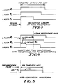
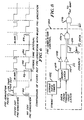
- Figures 3 through 6 are waveform diagrams useful in explaining the operation of the present invention.
- Figure 7 is a block diagram illustrating a preferred embodiment of the invention.
- Figure 8 is a schematic diagram illustrating the gating logic of Figure 7.
- the invention is suitable for use in a laser marking system.
- the system includes a laser head 10 containing a number of lasers, preferably CO2 lasers, which are excited by RF energy at approximately 27MHz to a nominal power of about 20 watts.
- the laser head typically will contain seven lasers, the outputs of which are directed through a beam delivery tube 12, via mirrors, onto a lens 14 which focuses the beams onto a marking area.
- the marking area is on the surface 16 of a conveyor system on which products to be marked are carried.
- the outputs of the lasers are focused by the lens to form a vertical column of beams, in the case of seven lasers a seven high vertical column. Because the products to be marked move transversely with respect to the vertical column it is possible to create a 7xn dot matrix from which alphanumeric characters may be generated by selectively controlling the beam energy of each laser. For purposes of this application it will be assumed that a 7x5 dot matrix is desired and thus each matrix is composed of five vertical strokes from the seven lasers as the substrate to be marked moves past the marking point (see Figure 2).
- the RF exitation for the lasers is generated by amplifiers 18 located in a control console, one amplifier for each laser.
- the amplifiers are controlled by digital signals from a computer system 20 via a laser interface circuit 22 according to the present invention.
- Each laser is separately controllable by a signal which turns the laser on or off depending on the particular character to be printed.
- a keyboard and CRT unit 24 permit the operator to communicate with the computer to enter data and alter the operation of the laser interface 22 as will be described.
- many computer systems can be employed as, for example, an Intel 80/24 single board computer system.
- each matrix which for exemplary purposes is 7x5, contains 35 dots.
- a 7x5 dot matrix there are five "strokes", each stroke being one of the vertical columns.
- To create the letter E for example, all lasers are turned on during the first stroke. During strokes 2 and 3 only lasers 1, 4 and 7 are turned on, while on strokes 4 and 5 only lasers 1 and 7 are on.
- a significant problem with laser marking is the between laser variation in output power. Matching seven or more lasers so that they have virtually identical output power is not easily accomplished. Even were this possible on a commercial scale, changes in operating characteristics over time would soon produce the same problem.
- One way to overcome the variation in output power is to determine the minimum amount of on time the weakest laser requires to make an acceptable dot and to then turn on all of the lasers for that amount of time.
- Such an approach results in the more powerful lasers having output energy which is more than required and causes the dots printed therefrom to be too large, resulting in unacceptable print quality.
- Another approach is to equalize laser output by varying the amplitude of the RF signal used to fire the laser. Under this scheme a weaker laser could be excited with a higher amplitude signal producing a higher output. This method, however, involves the use of more costly RF amplifiers and the need for circuitry to adjust the amplifiers as a function of the beam output.
- a low cost but highly effective method and apparatus are disclosed for equalizing laser output power.
- the invention obtains the desired result by independently controlling the "on" time of each laser. This reduces the effect of turn on delays and variations in laser power between units.
- This method is advantageous because it may be easily implemented at low cost. Specifically, only two states, on and off, need be provided and a simple RF amplifier may be utilized.
- FIG. 3 illustrates the turn on pulses for three of the seven lasers in a typical marking system.
- Laser No. 1 has been determined (arbitrarily) to be the laser with the lowest power output while laser No. 2 has an intermediate output and laser No. 3 the greatest output.
- At the beginning of a stroke (indicated by the vertical dashed line) all three lasers are turned on but remain on for different times, the on time corresponding inversely to their power output.
- laser No. 3 is on for the shortest period of time while laser No. 1 is on for the longest period of time. This will be referred to herein as weighting the on time pulse since it is typically obtained by calculating a weighting factor based on the laser having the lowest power output.
- the weighting factors which are provided to the computer, are used to turn on the more powerful lasers for a shorter time. This permits the energy output per laser to be equalized to a desired energy level.
- the operator selects a nominal on time pulse which is satisfactory for the weakest laser. He then determines the weighting factors for the remaining lasers (for example, a percentage of the weakest laser's on time).
- the computer then computes the actual on time for each other laser by multiplying the nominal on time by the weighting factor. This value is provided to the laser interface 22 as will be described.
- the appropriate delays may be empirically determined and provided to the computer system or they can be calculated by the computer from the weighting factors.
- weighting and pulse centering techniques provides a highly satisfactory result at relatively high energy levels (e.g., on time pulses greater than one millisecond). Additional techniques are necessary at low energy levels as may occur at high stroke rates (on time pulse widths less than 300 microseconds). This is because the on time pulse width at low energy levels is only two or three times longer than the turn on delays of the lasers. In fact, the slower lasers (those that have the greatest turn on delay) may have their output energy severely reduced at high stroke rates resulting in significantly less output power.
- the present invention it is possible to decrease turn on delay so that its effects become relatively insignificant. This is accomplished by applying RF energy to the laser for a short time at the beginning of each stroke pulse followed by a variable delay (which may be zero) before the beginning of the actual on time pulse for generating the dot. This permits the laser to respond much faster when it is turned on to print a dot.
- the use of a short pre-ionization pulse significantly decreases turn on delay without causing significant laser output prior to the on pulse used for marking. Such pre-ionization pulses are required only for a stroke on which a particular laser is designated to print a dot.
- FIG. 5 The concept of pre-ionizing a laser is illustrated in Figure 5.
- the vertical dashed line indicates the beginning of a stroke.
- a short pre-ionization pulse 30 is generated to prepare the laser to fire as soon as the on time pulse 32 is received.
- the pulse 30 may be followed by a short delay 34 before the on time pulse is received or, in fact, the delay 34 may be zero in which case the pre-ionization pulse is immediately followed by the on time pulse. Either pre-ionization technique works satisfactorily under the present circumstances.
- Whether or not to use a delay between the pulses is a consideration determined primarily by the stroke rate at which the system is operating and whether or not a modification to the ionization technique is employed, such modification being described hereafter under the heading "No Dot/Every Dot Pre-ionization".
- the pre-ionization pulses 30 are of a duration controlled by a single timer. If desired, a separate timer can be provided for each laser. This would permit separate adjustment of each pre-ionization timer for the turn on delay associated with a particular laser. Although separate timers for each laser provide best matching, a single timer provides adequate performance and reduces circuit complexity.
- a pre-ionization pulse is effective only if it occurs relatively close (within a few milliseconds) to the leading edge of the laser turn on pulse.
- high stroke rate printing a millisecond or less between strokes, for example
- each on pulse will itself provide pre-ionization for the next dot.
- high stroke rate, consecutive dots the use of a separate pre-ionization pulse interferes with proper printing by starting the laser too early thus contributing to, rather than decreasing differences in laser energy output.
- laser energy is better equalized by not providing a separate pre-ionization pulse but instead relying on the pre-ionizing effect of the on pulse for the dot printed during the previous stroke.
- the top waveform shows every dot pre-ionization as would occur at stroke rates below a threshold value.
- a pre-ionization pulse occurs before the on time pulse. Note, however, that in the case of a blank (no dot) there are no pre-ionization or on time pulses.
- a pre-ionization pulse is generated if and only if the laser had not been turned on during the previous stroke.
- a pre-ionization pulse is present at 40, 42 and 44 but not provided prior to turn on pulse 46 because the pre-ionization is accomplished by the prior on pulse 48 from the previous stroke.
- the logic determines whether the previous stroke was a dot or a blank and, if a dot, blocks the pre-ionization pulse to the RF amplifier.
- the computer 20 previously described, in addition to operator inputs via the keyboard, also receives signals from the conveyor system. These signals are indicated as the product detect and the shaft encoder signals.
- the first signal indicates that a product to be marked has reached the appropriate point for marking to commence.
- the shaft encoder signal indicates that it is time to initiate a stroke. This signal is derived from a rotating shaft associated with the conveyor system. Alternatively, a timer or oscillator may be employed to initiate stroke pulses a selected time after the product detect signal has been received.
- the computer 20 communicates with the various timing devices and logic associated with the invention through an address decode/write control device 70.
- the particular form of device is not critical but, for example, it may be a programmable array logic device included in an MMI PAL 14L8.
- the device 70 receives address data from the processor and responsive thereto directs associated data to selected devices connected to its output.
- the devices are a trigger latch 72, delay timers 74-76, pre-ionization timer 78, and pulse timers 80-82.
- the data from the computer is simply buffered by device 70 and sent to the device selected by the address decoder.
- the trigger latch 72 is loaded with the dot pattern data for each stroke and, when the stroke signal is received, activates the delay timers 74 through 76 and the pre-ionization timer 78 via bus 84.
- Delay timers 74 through 76 which provide the pulse centering function, communicate both with the trigger latch 72 and the address decode device 70.
- the appropriate delay value for a given laser is loaded in from the address decode 70 via the bus 86 while the trigger signal for the delay timers is received from the trigger latch 72 via bus 84. Only the delay timers for lasers which are to create a dot (rather than a blank) receive a signal from the trigger latch to initiate operation.
- each delay timer triggers the corresponding on pulse timer 80 through 82. These timers have also been previously loaded with a value to accomplish pulse weighting. The outputs of the pulse timers are provided to corresponding gating logic 88 through 90 which, as described subsequently in connection with Figure 8, provides the pre-ionization features of the invention.
- the number of timers and logic circuits provided is equal to the number of lasers utilized. Thus, there is a separate delay timer, pulse timer and gating logic circuit for each laser to be controlled. Conversely, there is but a single pre-ionization timer for all the lasers because of the small variation in turn on delay between laser devices although, if desired, a separate pre-ionization timer could be provided for each laser.
- the timers are preferably re-triggerable, one shot timers and, for example, Intel 8253 devices are suitable for this purpose.
- the timers are shown as discrete devices and this, in fact, is the preferred embodiment, it is possible to implement the timing function through a computer software routine where speed is not critical. In such case it would not be necessary to provide discrete timer devices to perform the functions specified.
- the logic circuit consists of a pre-ionization control section 100 ORed with the output signal, WP from the pulse timers 80 through 82.
- the pre-ionization control 100 includes a stroke rate timer 102, an inhibit latch 104 and a NAND gate 106.
- the stroke rate timer 102 receives the stroke signals from the computer 20 and determines the rate at which the strokes are generated. If the timer times out before another stroke is received, it indicates a sufficiently slow stroke rate that pre-ionization on every stroke is preferred.
- the stroke rate is low enough so that there is no concern that a previous on pulse has pre-ionized the laser making it undesirable to permit additional pre-ionization.
- the stroke rate timer does not time out, it indicates that the system is operating at a stroke rate fast enough so that it is necessary to selectively inhibit pre-ionization pulses.
- Inhibit latch 104 is reset by the stroke rate timer 102 if the latter times out thereby permitting a pre-ionization pulse to occur (unless inhibited by the other inputs to gate 106). In the absence of a reset signal, the operation of the inhibit latch is as follows.
- the pre-ionization timer 78 generates a signal at the beginning of each stroke. This signal, if not blocked by latch 104, generates a pre-ionization pulse of a duration determined by the pre-ionization timer setting.
- the data for a particular laser stroke (either a logic zero or a logic one from the trigger latch) is loaded into the inhibit latch by the trailing edge of the pre-ionization timer signal, PI . If the data is a logic one and the stroke rate is fast enough to avoid a reset from timer 102, the inhibit condition exists because the laser has been pre-ionized by the preceding stroke on pulse.
- the output of the latch 104 is a logical one but is inverted at 108 thereby blocking the ionization signal at gate 106. Conversely, if the data is a logic zero, a low output results from the latch which, in turn, enables gate 106 (assuming no other gate input is low).
- inhibit latch functions to monitor the data from the preceding stroke and inhibits the ionization pulse when necessary (assuming the stroke rate is fast enough).
- the other inputs to gate 106 are the pre-ionization pulse itself from the timer 78 via line 110, a manual disable switch via line 112, and a data signal from the trigger latch 72 via line 114.
- the signal on line 110 if the gate 106 is enabled, creates a pre-ionization pulse via gate 116 (an OR gate for negative logic signals).
- the input to gate 106 on line 114 is the data for the current stroke. Obviously if the laser is not to be turned on for that stroke (a blank is selected) there is no need for a pre-ionization pulse. It is, therefore, blocked by gate 106 when a logic zero is present on line 114.
- the sequence of printing an alphanumeric character begins when a product is detected.
- the computer then waits until a stroke is required (either generated internally by a programmable timer or externally generated from the shaft encoder signal). For every stroke the computer sends a seven bit pattern (for a seven laser system) to the trigger latch 72 via the address encode circuit 70. A logic one is sent if a dot is desired and a logic zero is sent if a blank or no dot is desired.
- the stroke signal is received by the trigger latch, it triggers the appropriate delay timers which begin counting to properly center the on pulses about a selected time reference.
- the outputs of the delay timers are connected to trigger the corresponding pulse timer when each delay timer times out.
- the pulse timers if triggered, generate the weighted on pulses corresponding to the relative power output of the particular laser with which it is associated.
- the outputs from the on pulse timers are gated with the pre-ionization pulse from the pre-ionization timer as shown in Figure 8. After triggering, the trigger latch 72 is cleared in preparation for the next stroke. When the next stroke signal is received the entire sequence repeats.
- the pre-ionization timer is triggered simultaneously with the trigger latch by the stroke signal.
- the pre-ionization timer output common to all lasers, is processed by the control logic of Figure 8.
- the pre-ionization pulse is allowed to pass through to the corresponding RF amplifier only under the following conditions:
- an improved laser marking device has been disclosed by virtue of a method and apparatus capable of equalizing the output performance of a plurality of lasers used to generate a dot matrix on a moving substrate.
Landscapes
- Physics & Mathematics (AREA)
- Optics & Photonics (AREA)
- Engineering & Computer Science (AREA)
- Plasma & Fusion (AREA)
- Mechanical Engineering (AREA)
- General Physics & Mathematics (AREA)
- Theoretical Computer Science (AREA)
- Lasers (AREA)
- Laser Beam Printer (AREA)
- Laser Beam Processing (AREA)
- Dot-Matrix Printers And Others (AREA)
- Exposure Or Original Feeding In Electrophotography (AREA)
Abstract
Description
- This invention relates to the field of marking devices for placing codes and the like on a substrate. More specifically, it relates to marking devices capable of placing alphanumeric codes, bar codes and other useful indicia on the surface of a product which moves relative to the marking device as, for example, on a conveyor. That device marks on objects moved past the laser beams. Alternatively, the present invention can be employed with a system which scans the beams across a stationary substrate, for example, using moving mirrors. Usually the marking is accomplished using a plurality of lasers having sufficient energy to permanently alter the surface of the product to be marked. One device with which the present invention may be employed is disclosed in European patent application EP-A-0 157 546 assigned to the present assignee which application is hereby incorporated by reference.
- Such a laser marking device employs a plurality of lasers, for example, seven. The output beam from each laser is sent through a beam delivery tube and a focusing lens onto the marking location. The seven beams are arranged by means of the lens to form a vertical column of seven beams, each capable of marking a dot onto the passing product. By moving the product transversely past the column, a dot matrix arrangement for printing alphanumeric characters is obtained in a manner well known in this art. By selectively turning on the lasers corresponding to the correct positions for a desired alphanumeric character, such symbols may be marked onto the product.
- Typically, a 5×7 dot matrix is employed and thus, for each character to be printed, the seven lasers must be turned on and off five times in a sequence which will place dots where required to form the character. Each character is formed by turning on selected lasers simultaneously five separate times (each time being referred to as a stroke) as the substrate of the article to be marked moves past the laser lens. In printing characters in this manner variations in laser energy output cause degradation of the print quality. Some dots are only partially formed or are missing entirely. Others are too large. This variation in laser output energy can result from: (1) variation in nominal laser output power, (2) turn on delay, (3) turn on and turn off time constants, (4) energy density and beam shape variation. Indeed efforts to match seven lasers so that their effective output power is essentially equal would be prohibitively expensive and perhaps impossible as power output can change over time. A method and apparatus for compensating for variations in the luminance characteristics of light emitting diodes in a print head by varying the individual L.E.D. conduction times is know from JP-A-61 142 816.
- The present invention discloses a method and apparatus for equalizing laser output by controlling the electrical drive signals for each laser as specified in
claims 1 and 8. The result substantially reduces the effect of laser performance variation on print quality. The control takes several forms. First, the relative energy output of each laser is determined and its on time is adjusted by appropriately weighting the on time of each laser relative to the weakest laser beam. Alternatively, the beam weighting can be relative to other references, such as average beam energy or even an independent reference value. The use of variable width "on" time pulses for the lasers can, however, introduce nonlinearity in the formed characters. To avoid or minimize this problem, all of the "on" pulses are centred about a selected time axis. Thus, the combination of weighted "on" pulses coupled with pulse centering provides a significant improvement in overall print quality. - For high stroke rates an additional problem arises from the inability of the lasers to cycle fast enough. This problem is reduced by selectively prei-onizing the lasers to reduce turn on delay to permit significantly higher stroke rates while maintaining marking quality. Various pre-ionizing schemes may be employed depending upon the desired application.
- Pre-ionisation of lasers per se is known from US-A-4 287 483.
- It is accordingly an object of the present invention to provide an improved method and apparatus for equalizing the power output of the individual lasers employed in a laser marking system.
- A further object of the invention is to provide a method and apparatus for varying the "on" pulse width of each laser in such a marking system to substantially equalize the energy outputs thereof.
- Another object of the invention is to provide a method and apparatus for centering the "on" pulses used to trigger the lasers to insure vertical linearity of the energy dots produced therefrom for marking a moving substrate.
- A further object of the invention is to provide a method and means whereby high stroke rates may be obtained by pre-ionizing the lasers to reduce turn on delay.
- Other objects and advantages of the invention will be apparent from the remaining portion of the specification.
- Figure 1 is a schematic representation of a marking system incorporating the teachings of the present invention.
- Figure 2 is a representation of a dot matrix useful in explaining the marking arrangement of the present invention.
- Figures 3 through 6 are waveform diagrams useful in explaining the operation of the present invention.
- Figure 7 is a block diagram illustrating a preferred embodiment of the invention.
- Figure 8 is a schematic diagram illustrating the gating logic of Figure 7.
- Referring to Figure 1, the invention is suitable for use in a laser marking system. The system includes a laser head 10 containing a number of lasers, preferably CO₂ lasers, which are excited by RF energy at approximately 27MHz to a nominal power of about 20 watts. The laser head typically will contain seven lasers, the outputs of which are directed through a beam delivery tube 12, via mirrors, onto a
lens 14 which focuses the beams onto a marking area. In Figure 1 the marking area is on thesurface 16 of a conveyor system on which products to be marked are carried. - In the usual arrangement the outputs of the lasers are focused by the lens to form a vertical column of beams, in the case of seven lasers a seven high vertical column. Because the products to be marked move transversely with respect to the vertical column it is possible to create a 7xn dot matrix from which alphanumeric characters may be generated by selectively controlling the beam energy of each laser. For purposes of this application it will be assumed that a 7x5 dot matrix is desired and thus each matrix is composed of five vertical strokes from the seven lasers as the substrate to be marked moves past the marking point (see Figure 2).
- The RF exitation for the lasers is generated by
amplifiers 18 located in a control console, one amplifier for each laser. In turn,the amplifiers are controlled by digital signals from acomputer system 20 via a laser interface circuit 22 according to the present invention. Each laser is separately controllable by a signal which turns the laser on or off depending on the particular character to be printed. A keyboard andCRT unit 24 permit the operator to communicate with the computer to enter data and alter the operation of the laser interface 22 as will be described. As will be recognized by those skilled in the art, many computer systems can be employed as, for example, an Intel 80/24 single board computer system. - For a more detailed description of the laser marking apparatus per se, see European patent application EP-A-0-157 546.
- Referring to Figure 2, there is shown a representation of the typical dot matrix which is created by the laser marking device of Figure 1. Each matrix, which for exemplary purposes is 7x5, contains 35 dots. To generate useful information as, for example, to create the letters E and H, only selected dots are marked onto the substrate as it moves past the marking location. In a 7x5 dot matrix there are five "strokes", each stroke being one of the vertical columns. To create the letter E, for example, all lasers are turned on during the first stroke. During
strokes lasers lasers - A significant problem with laser marking is the between laser variation in output power. Matching seven or more lasers so that they have virtually identical output power is not easily accomplished. Even were this possible on a commercial scale, changes in operating characteristics over time would soon produce the same problem. One way to overcome the variation in output power is to determine the minimum amount of on time the weakest laser requires to make an acceptable dot and to then turn on all of the lasers for that amount of time. However, such an approach results in the more powerful lasers having output energy which is more than required and causes the dots printed therefrom to be too large, resulting in unacceptable print quality.
- Another approach is to equalize laser output by varying the amplitude of the RF signal used to fire the laser. Under this scheme a weaker laser could be excited with a higher amplitude signal producing a higher output. This method, however, involves the use of more costly RF amplifiers and the need for circuitry to adjust the amplifiers as a function of the beam output.
- According to the present invention, a low cost but highly effective method and apparatus are disclosed for equalizing laser output power. The invention obtains the desired result by independently controlling the "on" time of each laser. This reduces the effect of turn on delays and variations in laser power between units. This method is advantageous because it may be easily implemented at low cost. Specifically, only two states, on and off, need be provided and a simple RF amplifier may be utilized.
- Referring to Figures 3 and 4, waveforms illustrating the operation of the invention are shown. Figure 3 illustrates the turn on pulses for three of the seven lasers in a typical marking system. Laser No. 1 has been determined (arbitrarily) to be the laser with the lowest power output while laser No. 2 has an intermediate output and laser No. 3 the greatest output. At the beginning of a stroke (indicated by the vertical dashed line) all three lasers are turned on but remain on for different times, the on time corresponding inversely to their power output. Thus, laser No. 3 is on for the shortest period of time while laser No. 1 is on for the longest period of time. This will be referred to herein as weighting the on time pulse since it is typically obtained by calculating a weighting factor based on the laser having the lowest power output.
- The weighting factors, which are provided to the computer, are used to turn on the more powerful lasers for a shorter time. This permits the energy output per laser to be equalized to a desired energy level. Thus, the operator selects a nominal on time pulse which is satisfactory for the weakest laser. He then determines the weighting factors for the remaining lasers (for example, a percentage of the weakest laser's on time). The computer then computes the actual on time for each other laser by multiplying the nominal on time by the weighting factor. This value is provided to the laser interface 22 as will be described.
- Simply weighting the lasers on times to obtain equal power output would be satisfactory in a static or low speed marking system. Where, however, a dot matrix marking system is employed which relies upon relative movement between substrate and the laser beams, simply weighting the outputs does not produce completely satisfactory results. Variations in the on time for each laser produced by weighting may result in nonlinearity or skewing of the dots. This effect occurs because the weaker lasers stay on for a longer time so that the center of the dot is shifted relative to the dots created by the stronger lasers, due to movement of the substrate. The severity of nonlinearity depends on (1) the magnitude of the differences in weighting factors, (2) the speed of the substrate and (3) the stroke rate of the marking system. For high speed marking with severely mismatched lasers the weighting technique alone produces unacceptable marking quality.
- A solution to the problem of nonlinearity is illustrated in Figure 4. The weighting factors are retained and thus
lasers lasers lasers - The use of weighting and pulse centering techniques provides a highly satisfactory result at relatively high energy levels (e.g., on time pulses greater than one millisecond). Additional techniques are necessary at low energy levels as may occur at high stroke rates (on time pulse widths less than 300 microseconds). This is because the on time pulse width at low energy levels is only two or three times longer than the turn on delays of the lasers. In fact, the slower lasers (those that have the greatest turn on delay) may have their output energy severely reduced at high stroke rates resulting in significantly less output power.
- According to the present invention it is possible to decrease turn on delay so that its effects become relatively insignificant. This is accomplished by applying RF energy to the laser for a short time at the beginning of each stroke pulse followed by a variable delay (which may be zero) before the beginning of the actual on time pulse for generating the dot. This permits the laser to respond much faster when it is turned on to print a dot. The use of a short pre-ionization pulse significantly decreases turn on delay without causing significant laser output prior to the on pulse used for marking. Such pre-ionization pulses are required only for a stroke on which a particular laser is designated to print a dot.
- The concept of pre-ionizing a laser is illustrated in Figure 5. The vertical dashed line indicates the beginning of a stroke. A
short pre-ionization pulse 30 is generated to prepare the laser to fire as soon as the ontime pulse 32 is received. As indicated, thepulse 30 may be followed by a short delay 34 before the on time pulse is received or, in fact, the delay 34 may be zero in which case the pre-ionization pulse is immediately followed by the on time pulse. Either pre-ionization technique works satisfactorily under the present circumstances. Whether or not to use a delay between the pulses is a consideration determined primarily by the stroke rate at which the system is operating and whether or not a modification to the ionization technique is employed, such modification being described hereafter under the heading "No Dot/Every Dot Pre-ionization". - As will be described in connection with the pre-ionization timer in Figure 7, the
pre-ionization pulses 30 are of a duration controlled by a single timer. If desired, a separate timer can be provided for each laser. This would permit separate adjustment of each pre-ionization timer for the turn on delay associated with a particular laser. Although separate timers for each laser provide best matching, a single timer provides adequate performance and reduces circuit complexity. - In studying the effects of pre-ionization pulses on laser turn on, it has been determined that a pre-ionization pulse is effective only if it occurs relatively close (within a few milliseconds) to the leading edge of the laser turn on pulse. However, during high stroke rate printing (a millisecond or less between strokes, for example), if a particular laser prints dots for two or more consecutive strokes, each on pulse will itself provide pre-ionization for the next dot. Under these very special circumstances (high stroke rate, consecutive dots) the use of a separate pre-ionization pulse interferes with proper printing by starting the laser too early thus contributing to, rather than decreasing differences in laser energy output. In such a case laser energy is better equalized by not providing a separate pre-ionization pulse but instead relying on the pre-ionizing effect of the on pulse for the dot printed during the previous stroke.
- In order to account for this phenomenon, it is necessary to detect stroke rate and whether or not a particular laser was fired during the previous stroke before permitting a pre-ionizing pulse to occur. As described in connection with Figure 8, a no dot/every dot circuit is provided to detect stroke rates which are fast enough to require suppressing the pre-ionizing pulse and whether or not a particular laser was fired on the previous stroke. Thus, for example, at high stroke rates if no dot (a blank) was generated, it is still necessary to provide a pre-ionization pulse. The effect of the circuit of Figure 8 is to insert pre-ionization pulses, at high stroke rates, only before dots which are preceded by blanks. The function of the circuit is shown in Figure 6. The top waveform shows every dot pre-ionization as would occur at stroke rates below a threshold value. Thus, each time a stroke occurs, a pre-ionization pulse occurs before the on time pulse. Note, however, that in the case of a blank (no dot) there are no pre-ionization or on time pulses.
- In the lower waveform there is a representation of the no dot pre-ionization mode wherein a pre-ionization pulse is generated if and only if the laser had not been turned on during the previous stroke. Thus, a pre-ionization pulse is present at 40, 42 and 44 but not provided prior to turn on
pulse 46 because the pre-ionization is accomplished by the prior onpulse 48 from the previous stroke. In effect, the logic determines whether the previous stroke was a dot or a blank and, if a dot, blocks the pre-ionization pulse to the RF amplifier. - Referring now to Figure 7, a block diagram of the hardware implementation of the invention is illustrated. The
computer 20, previously described, in addition to operator inputs via the keyboard, also receives signals from the conveyor system. These signals are indicated as the product detect and the shaft encoder signals. The first signal indicates that a product to be marked has reached the appropriate point for marking to commence. The shaft encoder signal indicates that it is time to initiate a stroke. This signal is derived from a rotating shaft associated with the conveyor system. Alternatively, a timer or oscillator may be employed to initiate stroke pulses a selected time after the product detect signal has been received. Thecomputer 20 communicates with the various timing devices and logic associated with the invention through an address decode/write control device 70. The particular form of device is not critical but, for example, it may be a programmable array logic device included in an MMI PAL 14L8. Thedevice 70 receives address data from the processor and responsive thereto directs associated data to selected devices connected to its output. In this case the devices are atrigger latch 72, delay timers 74-76,pre-ionization timer 78, and pulse timers 80-82. The data from the computer is simply buffered bydevice 70 and sent to the device selected by the address decoder. - The
trigger latch 72 is loaded with the dot pattern data for each stroke and, when the stroke signal is received, activates the delay timers 74 through 76 and thepre-ionization timer 78 viabus 84. Delay timers 74 through 76, which provide the pulse centering function, communicate both with thetrigger latch 72 and theaddress decode device 70. The appropriate delay value for a given laser is loaded in from the address decode 70 via thebus 86 while the trigger signal for the delay timers is received from thetrigger latch 72 viabus 84. Only the delay timers for lasers which are to create a dot (rather than a blank) receive a signal from the trigger latch to initiate operation. - The output of each delay timer triggers the corresponding on
pulse timer 80 through 82. These timers have also been previously loaded with a value to accomplish pulse weighting. The outputs of the pulse timers are provided to corresponding gating logic 88 through 90 which, as described subsequently in connection with Figure 8, provides the pre-ionization features of the invention. - As indicated in Figure 7, the number of timers and logic circuits provided is equal to the number of lasers utilized. Thus, there is a separate delay timer, pulse timer and gating logic circuit for each laser to be controlled. Conversely, there is but a single pre-ionization timer for all the lasers because of the small variation in turn on delay between laser devices although, if desired, a separate pre-ionization timer could be provided for each laser.
- The timers are preferably re-triggerable, one shot timers and, for example, Intel 8253 devices are suitable for this purpose. Although the timers are shown as discrete devices and this, in fact, is the preferred embodiment, it is possible to implement the timing function through a computer software routine where speed is not critical. In such case it would not be necessary to provide discrete timer devices to perform the functions specified.
- Referring now to Figure 8, an example of the gating logic circuits 88-90 is shown in detail. The logic circuit consists of a
pre-ionization control section 100 ORed with the output signal,WP from thepulse timers 80 through 82. Thepre-ionization control 100 includes astroke rate timer 102, an inhibit latch 104 and a NAND gate 106. Thestroke rate timer 102 receives the stroke signals from thecomputer 20 and determines the rate at which the strokes are generated. If the timer times out before another stroke is received, it indicates a sufficiently slow stroke rate that pre-ionization on every stroke is preferred. More specifically, the stroke rate is low enough so that there is no concern that a previous on pulse has pre-ionized the laser making it undesirable to permit additional pre-ionization. Conversely, if the stroke rate timer does not time out, it indicates that the system is operating at a stroke rate fast enough so that it is necessary to selectively inhibit pre-ionization pulses. - Inhibit latch 104 is reset by the
stroke rate timer 102 if the latter times out thereby permitting a pre-ionization pulse to occur (unless inhibited by the other inputs to gate 106). In the absence of a reset signal, the operation of the inhibit latch is as follows. - The
pre-ionization timer 78 generates a signal at the beginning of each stroke. This signal, if not blocked by latch 104, generates a pre-ionization pulse of a duration determined by the pre-ionization timer setting. The data for a particular laser stroke (either a logic zero or a logic one from the trigger latch) is loaded into the inhibit latch by the trailing edge of the pre-ionization timer signal,PI . If the data is a logic one and the stroke rate is fast enough to avoid a reset fromtimer 102, the inhibit condition exists because the laser has been pre-ionized by the preceding stroke on pulse. The output of the latch 104 is a logical one but is inverted at 108 thereby blocking the ionization signal at gate 106. Conversely, if the data is a logic zero, a low output results from the latch which, in turn, enables gate 106 (assuming no other gate input is low). - Thus the inhibit latch functions to monitor the data from the preceding stroke and inhibits the ionization pulse when necessary (assuming the stroke rate is fast enough).
- The other inputs to gate 106 are the pre-ionization pulse itself from the
timer 78 vialine 110, a manual disable switch vialine 112, and a data signal from thetrigger latch 72 via line 114. The signal online 110, if the gate 106 is enabled, creates a pre-ionization pulse via gate 116 (an OR gate for negative logic signals). - The input to gate 106 on line 114 is the data for the current stroke. Obviously if the laser is not to be turned on for that stroke (a blank is selected) there is no need for a pre-ionization pulse. It is, therefore, blocked by gate 106 when a logic zero is present on line 114.
- Operation of the circuit of Figures 7 and 8 is as follows. The system operator enters time values into the computer. In turn, these values are loaded into the timers. Specifically, the operator enters values for the
pre-ionization timer 78, the stroke delay timers 74 through 76, thepulse timers 80 through 82 and thestroke rate timer 102. - The sequence of printing an alphanumeric character begins when a product is detected. The computer then waits until a stroke is required (either generated internally by a programmable timer or externally generated from the shaft encoder signal). For every stroke the computer sends a seven bit pattern (for a seven laser system) to the
trigger latch 72 via the address encodecircuit 70. A logic one is sent if a dot is desired and a logic zero is sent if a blank or no dot is desired. When the stroke signal is received by the trigger latch, it triggers the appropriate delay timers which begin counting to properly center the on pulses about a selected time reference. - The outputs of the delay timers are connected to trigger the corresponding pulse timer when each delay timer times out. The pulse timers, if triggered, generate the weighted on pulses corresponding to the relative power output of the particular laser with which it is associated.
- The outputs from the on pulse timers are gated with the pre-ionization pulse from the pre-ionization timer as shown in Figure 8. After triggering, the
trigger latch 72 is cleared in preparation for the next stroke. When the next stroke signal is received the entire sequence repeats. - The pre-ionization timer is triggered simultaneously with the trigger latch by the stroke signal. The pre-ionization timer output, common to all lasers, is processed by the control logic of Figure 8. The pre-ionization pulse is allowed to pass through to the corresponding RF amplifier only under the following conditions:
- (1) The pre-ionization function has not been manually disabled by switch SW1 on
line 112. - (2) The data bit in the stroke pattern calls for a dot (rather than a blank).
- (3) The stroke period is greater than the threshold value contained in the stroke rate timer l02, or if the stroke period is less than the stroke rate timer value the previous stroke data bit called for a blank.
- From the foregoing it will be apparent that an improved laser marking device has been disclosed by virtue of a method and apparatus capable of equalizing the output performance of a plurality of lasers used to generate a dot matrix on a moving substrate.
- While we have shown and described embodiments of the invention, it will be understood that this description and illustrations are offered merely by way of example, and that the invention is to be limited in scope only as to the appended claims.
Claims (11)
- Apparatus for increasing the stroke rate of a laser marking system employing a plurality of lasers (10) which are caused to scan a substrate to mark symbols thereon comprising:(a) means for determining the stroke rate (102) at which the marking is occurring;(b) means for producing short duration pre-ionizing pulses (78), (104) just prior to laser turn on for:whereby the lasers to be turned on are pre-ionized to reduce turn on delay, the pre-ionizing pulses being inhibited at high stroke rates where the desired pre-ionizing effect is obtained from the on time period of the immediately preceding marking stroke.(i) all of the lasers to be energized if said stroke rate is less than a selected value;(ii) only those lasers to be energized which were not energized on the immediately preceding marking stroke if said stroke rate is at least equal to said selected value;
- Apparatus according to claim 1, wherein said means for producing pre-ionizing pulses includes:(a) a pre-ionization timer (78), the output of which determines the duration of said pre-ionization pulses;(b) means for gating said pre-ionization timer output (104) as a function of at least said stroke rate determining means.
- Apparatus according to claim 1 or claim 2, further comprising(a) means for adjusting the on time period (80),(81),(82) of each laser as a function of its energy output relative to a reference value thereby to equalize said energy outputs;(b) means for centering the on time periods (74),(75),(76) of said lasers about a common time reference point to maintain marking quality.
- Apparatus according to claim 3, wherein said adjusting means are a plurality of presettable pulse timers (80),(81),(82), one for each laser, said pulse timers, when triggered, determining the on time period of the lasers.
- Apparatus according to claim 3 or claim 4, wherein said centering means are a plurality of presettable delay timers (74),(75),(76), one for each laser, said delay timers triggering said pulse timers in the correct sequence to center the on time period of the lasers about said common time reference point.
- Apparatus according to any preceding claim, wherein said determining means is a stroke rate timer (102) producing a first output signal if the stroke rate is below a selected threshold value and a second output signal otherwise, said means for producing pre-ionizing pulses being responsive thereto.
- Apparatus according to any preceding claim, wherein the laser outputs are arranged in a linear column and caused to scan a substrate for repetitively marking (stroking) dots onto said substrate to form symbols.
- A method for facilitating an increase in the stroke rate of a laser marking system employing a plurality of lasers which are caused to scan a substrate to mark symbols thereon comprising the steps of:(a) determining the stroke rate at which the marking is occurring;(b) pulsing, for a short duration prior to the on time period of each laser, all of the lasers to be energised if said stroke rate is less than a selected value;(c) pulsing, for a short duration prior to the on time period of each laser, only those lasers to be energized which were not energized on the immediately preceding marking stroke if said stroke rate is at least equal to said selected value;whereby the lasers to be turned on are pre-ionized to reduce turn on delay, the pre-ionizing pulses being inhibited at high stroke rates where the desired pre-ionizing effect is obtained from the on time period of the immediately preceding marking stroke.
- A method according to claim 8, wherein said pre-ionizing pulses are produced using:(a) a pre-ionization timer, the output of which determines the duration of said pre-ionization pulses;(b) means for gating said pre-ionization timer output as a function of at least said stroke rate determining means.
- A method according to claim 8 or claim 9, wherein the energy outputs of the lasers are equalised by:(a) adjusting the on time period of each laser as a function of its energy output relative to a reference value thereby to equalize said energy outputs;(b) centering the on time periods of said lasers about a common time reference point to maintain marking quality.
- A method according to any one of claims 8 to 10, wherein the laser marking system comprises a plurality of laser outputs arranged in a linear column and caused to scan a substrate for repetitively marking (stroking) dots onto said substrate to form symbols.
Applications Claiming Priority (2)
| Application Number | Priority Date | Filing Date | Title |
|---|---|---|---|
| US06/894,366 US4720618A (en) | 1986-08-07 | 1986-08-07 | Method and apparatus for equalizing power output in a laser marking system |
| US894366 | 1992-06-04 |
Publications (3)
| Publication Number | Publication Date |
|---|---|
| EP0256706A2 EP0256706A2 (en) | 1988-02-24 |
| EP0256706A3 EP0256706A3 (en) | 1989-08-09 |
| EP0256706B1 true EP0256706B1 (en) | 1994-10-12 |
Family
ID=25402978
Family Applications (1)
| Application Number | Title | Priority Date | Filing Date |
|---|---|---|---|
| EP87306687A Expired - Lifetime EP0256706B1 (en) | 1986-08-07 | 1987-07-29 | Method and apparatus for equalizing power output in a laser marking system |
Country Status (6)
| Country | Link |
|---|---|
| US (1) | US4720618A (en) |
| EP (1) | EP0256706B1 (en) |
| JP (1) | JP2509236B2 (en) |
| AT (1) | ATE112873T1 (en) |
| CA (1) | CA1292286C (en) |
| DE (1) | DE3750649D1 (en) |
Families Citing this family (44)
| Publication number | Priority date | Publication date | Assignee | Title |
|---|---|---|---|---|
| US4780607A (en) * | 1987-08-24 | 1988-10-25 | United Technologies Corporation | Laser beam power monitoring arrangement |
| US4997994A (en) * | 1989-09-01 | 1991-03-05 | At&T Bell Laboratories | Article having marking thereon and methods of making |
| US5474627A (en) * | 1990-10-11 | 1995-12-12 | Aerospatiale Societe Nationale Industrielle | Method for marking an electric cable |
| US5247154A (en) * | 1991-01-17 | 1993-09-21 | Westinghouse Electric Corp. | Method and apparatus for monitoring the laser marking of a bar code label |
| ES2102455T3 (en) * | 1991-01-17 | 1997-08-01 | United Distillers Plc | DYNAMIC MARKING WITH LASER. |
| AU3235393A (en) * | 1991-12-04 | 1993-06-28 | Colorado Laser Marking, Inc. | Apparatus and method for marking thin walled tubes |
| US5294770A (en) * | 1992-01-14 | 1994-03-15 | Alza Corporation | Laser tablet treatment system with dual access to tablet |
| US5341157A (en) * | 1992-08-14 | 1994-08-23 | Bumb & Associates | Laser-driven silk screen mask device |
| US5508080A (en) * | 1994-02-17 | 1996-04-16 | Takashimaya Nippatsu Kogyo Co. Ltd. | Flexible laminated surface material and method of producing the same |
| US5658474A (en) * | 1994-12-16 | 1997-08-19 | Alza Corporation | Method and apparatus for forming dispenser delivery ports |
| US6027195A (en) * | 1996-11-12 | 2000-02-22 | Varis Corporation | System and method for synchronizing the piezoelectric clock sources of a plurality of ink jet printheads |
| US6791592B2 (en) * | 2000-04-18 | 2004-09-14 | Laserink | Printing a code on a product |
| CA2406085C (en) * | 2000-04-18 | 2009-10-27 | Laserink | Printing a code on a product |
| US20030047538A1 (en) * | 2001-09-12 | 2003-03-13 | Paul Trpkovski | Laser etching indicia apparatus |
| DE10224372A1 (en) * | 2002-05-24 | 2003-12-11 | Jenoptik Automatisierungstech | Code-reading method for applying/reading out encoding of any length on moving material uses a laser beam switched on and off by controlling electronics |
| US20050088510A1 (en) * | 2003-10-24 | 2005-04-28 | Shlomo Assa | Low angle optics and reversed optics |
| US7046267B2 (en) * | 2003-12-19 | 2006-05-16 | Markem Corporation | Striping and clipping correction |
| US20050271096A1 (en) * | 2004-04-12 | 2005-12-08 | Rolland Zeleny | Laser output temperature compensation |
| US20060012821A1 (en) * | 2004-07-12 | 2006-01-19 | Kevin Franklin | Laser marking user interface |
| US7394479B2 (en) | 2005-03-02 | 2008-07-01 | Marken Corporation | Pulsed laser printing |
| US8657098B2 (en) * | 2010-01-20 | 2014-02-25 | Ten Media, Llc | Systems and methods for processing eggs |
| US8499718B2 (en) * | 2010-01-20 | 2013-08-06 | Ten Media, Llc | Systems and methods for processing eggs |
| US20110177208A1 (en) * | 2010-01-20 | 2011-07-21 | Newmarket Impressions, Llc | Systems and methods for processing eggs |
| JP5913134B2 (en) | 2010-01-20 | 2016-04-27 | テン メディア,エルエルシー | Systems and methods for processing eggs and other objects |
| US8455030B2 (en) * | 2010-01-20 | 2013-06-04 | Ten Media, Llc | Systems and methods for processing eggs |
| US8823758B2 (en) | 2010-01-20 | 2014-09-02 | Ten Media, Llc | Systems and methods for processing eggs |
| US8715757B2 (en) * | 2010-01-20 | 2014-05-06 | Ten Media, Llc | Systems and methods for processing eggs |
| US8455026B2 (en) | 2010-01-20 | 2013-06-04 | Ten Media, Llc | Systems and methods for processing eggs |
| EP2564973B1 (en) | 2011-09-05 | 2014-12-10 | ALLTEC Angewandte Laserlicht Technologie Gesellschaft mit beschränkter Haftung | Marking apparatus with a plurality of lasers and a combining deflection device |
| EP2565998A1 (en) | 2011-09-05 | 2013-03-06 | ALLTEC Angewandte Laserlicht Technologie Gesellschaft mit beschränkter Haftung | Gas ring laser device |
| EP2565673B1 (en) | 2011-09-05 | 2013-11-13 | ALLTEC Angewandte Laserlicht Technologie Gesellschaft mit beschränkter Haftung | Device and method for marking of an object by means of a laser beam |
| EP2565996B1 (en) | 2011-09-05 | 2013-12-11 | ALLTEC Angewandte Laserlicht Technologie Gesellschaft mit beschränkter Haftung | Laser device with a laser unit, and a fluid container for a cooling means of said laser unit |
| EP2564975B1 (en) | 2011-09-05 | 2014-12-10 | ALLTEC Angewandte Laserlicht Technologie Gesellschaft mit beschränkter Haftung | Marking apparatus with a plurality of lasers and individually adjustable sets of deflection means |
| EP2564976B1 (en) | 2011-09-05 | 2015-06-10 | ALLTEC Angewandte Laserlicht Technologie Gesellschaft mit beschränkter Haftung | Marking apparatus with at least one gas laser and heat dissipator |
| DK2565994T3 (en) | 2011-09-05 | 2014-03-10 | Alltec Angewandte Laserlicht Technologie Gmbh | Laser device and method for marking an object |
| EP2564972B1 (en) | 2011-09-05 | 2015-08-26 | ALLTEC Angewandte Laserlicht Technologie Gesellschaft mit beschränkter Haftung | Marking apparatus with a plurality of lasers, deflection means and telescopic means for each laser beam |
| ES2450467T3 (en) | 2011-09-05 | 2014-03-24 | ALLTEC Angewandte Laserlicht Technologie Gesellschaft mit beschränkter Haftung | Laser device and laser light generation procedure |
| EP2564970B1 (en) | 2011-09-05 | 2015-08-26 | ALLTEC Angewandte Laserlicht Technologie Gesellschaft mit beschränkter Haftung | Marking device for marking an object with marking light with different light modules employing different marking technologies |
| ES2544269T3 (en) | 2011-09-05 | 2015-08-28 | ALLTEC Angewandte Laserlicht Technologie Gesellschaft mit beschränkter Haftung | Marking apparatus with a plurality of gas lasers with resonance tubes and deflection means individually adjustable |
| EP2564971B1 (en) | 2011-09-05 | 2015-08-26 | ALLTEC Angewandte Laserlicht Technologie Gesellschaft mit beschränkter Haftung | Marking apparatus with a plurality of laser and a set of deflecting means |
| ES2446364T3 (en) | 2011-09-05 | 2014-03-07 | ALLTEC Angewandte Laserlicht Technologie Gesellschaft mit beschränkter Haftung | Gas laser device with gas tank |
| US9315317B2 (en) | 2012-02-21 | 2016-04-19 | Ten Media, Llc | Container for eggs |
| US20140336029A1 (en) * | 2013-05-07 | 2014-11-13 | The Procter & Gamble Company | Process for laser puncturing holes into water-soluble films |
| US10583668B2 (en) | 2018-08-07 | 2020-03-10 | Markem-Imaje Corporation | Symbol grouping and striping for wide field matrix laser marking |
Family Cites Families (9)
| Publication number | Priority date | Publication date | Assignee | Title |
|---|---|---|---|---|
| DE2726454B2 (en) * | 1977-06-11 | 1979-08-23 | Hoesch Werke Ag, 4600 Dortmund | Method for marking moving panels and strips |
| DE2853258A1 (en) * | 1978-12-09 | 1980-06-12 | Hoesch Werke Ag | METHOD AND ARRANGEMENT FOR APPLYING A MARKING ON THE SURFACE OF MOVING TABLES AND TAPES |
| US4287483A (en) * | 1979-09-04 | 1981-09-01 | Raytheon Company | Transverse excitation laser |
| JPS56152373A (en) * | 1980-04-24 | 1981-11-25 | Fuji Photo Film Co Ltd | Laser recording device |
| US4546995A (en) * | 1982-11-02 | 1985-10-15 | Kassai Kabushikikaisha | Collapsible luggage carrier |
| US4652722A (en) * | 1984-04-05 | 1987-03-24 | Videojet Systems International, Inc. | Laser marking apparatus |
| JPH0614610B2 (en) * | 1984-12-17 | 1994-02-23 | 沖電気工業株式会社 | Pulse width control circuit |
| NL8403926A (en) * | 1984-12-24 | 1986-07-16 | Oce Nederland Bv | METHOD FOR EXPOSING A PHOTOSENSITIVE LAYER AND EXPOSURE DEVICE. |
| JP2503202B2 (en) * | 1985-01-30 | 1996-06-05 | 株式会社リコー | Output control device for semiconductor laser |
-
1986
- 1986-08-07 US US06/894,366 patent/US4720618A/en not_active Expired - Fee Related
-
1987
- 1987-07-28 CA CA000543181A patent/CA1292286C/en not_active Expired - Fee Related
- 1987-07-29 EP EP87306687A patent/EP0256706B1/en not_active Expired - Lifetime
- 1987-07-29 DE DE3750649T patent/DE3750649D1/en not_active Expired - Lifetime
- 1987-07-29 AT AT87306687T patent/ATE112873T1/en active
- 1987-08-07 JP JP62196500A patent/JP2509236B2/en not_active Expired - Lifetime
Also Published As
| Publication number | Publication date |
|---|---|
| DE3750649D1 (en) | 1994-11-17 |
| CA1292286C (en) | 1991-11-19 |
| JP2509236B2 (en) | 1996-06-19 |
| EP0256706A3 (en) | 1989-08-09 |
| JPS6342191A (en) | 1988-02-23 |
| EP0256706A2 (en) | 1988-02-24 |
| US4720618A (en) | 1988-01-19 |
| ATE112873T1 (en) | 1994-10-15 |
Similar Documents
| Publication | Publication Date | Title |
|---|---|---|
| US4727235A (en) | Method and apparatus for equalizing power output in a laser marking system | |
| US4720618A (en) | Method and apparatus for equalizing power output in a laser marking system | |
| US3866533A (en) | Electrical print impression control | |
| US4503444A (en) | Method and apparatus for generating a gray scale with a high speed thermal ink jet printer | |
| EP0518670A3 (en) | Ink jet recording apparatus | |
| CA1138803A (en) | Print hammer drive circuit with compensation for voltage variation | |
| JPH0450191B2 (en) | ||
| US5442383A (en) | Ink jet printer with a device for determining a printing interval | |
| CA1186782A (en) | Control system for timing hammers of impact printers | |
| EP0147520B1 (en) | Thermal printer, thermal printing method and process for lifting off wrongly typed characters | |
| EP1101144A1 (en) | Laser printer having variable beam spacing | |
| US5408483A (en) | Laser beam emitting device with selective laser beam power output level | |
| EP4080299A1 (en) | System and method for laser marking a graphic on an object | |
| US5263994A (en) | Printer having a plurality of printing modes | |
| US4169683A (en) | High speed wire printing device | |
| CA1324026C (en) | Halftone printing system | |
| EP1093929A2 (en) | Ink jet printer and its preliminary driving method | |
| US4848943A (en) | Method and apparatus for energizing a printhead | |
| EP0595095B1 (en) | Thermal printer system and operating method | |
| US6474770B1 (en) | Adjustment of ink droplet expulsion testing device in printer | |
| JP2919139B2 (en) | Laser marking processing method and apparatus | |
| JP3175916B2 (en) | Ink jet recording device | |
| JPS5916773A (en) | Printer | |
| US9630401B2 (en) | Printhead calibration and printing | |
| EP0329371B1 (en) | Method and apparatus for setting character width in printer |
Legal Events
| Date | Code | Title | Description |
|---|---|---|---|
| PUAI | Public reference made under article 153(3) epc to a published international application that has entered the european phase |
Free format text: ORIGINAL CODE: 0009012 |
|
| AK | Designated contracting states |
Kind code of ref document: A2 Designated state(s): AT BE CH DE ES FR GB GR IT LI LU NL SE |
|
| PUAL | Search report despatched |
Free format text: ORIGINAL CODE: 0009013 |
|
| AK | Designated contracting states |
Kind code of ref document: A3 Designated state(s): AT BE CH DE ES FR GB GR IT LI LU NL SE |
|
| 17P | Request for examination filed |
Effective date: 19891108 |
|
| 17Q | First examination report despatched |
Effective date: 19910409 |
|
| RAP1 | Party data changed (applicant data changed or rights of an application transferred) |
Owner name: VIDEOJET SYSTEMS INTERNATIONAL, INC. |
|
| GRAA | (expected) grant |
Free format text: ORIGINAL CODE: 0009210 |
|
| AK | Designated contracting states |
Kind code of ref document: B1 Designated state(s): AT BE CH DE ES FR GB GR IT LI LU NL SE |
|
| PG25 | Lapsed in a contracting state [announced via postgrant information from national office to epo] |
Ref country code: IT Free format text: LAPSE BECAUSE OF FAILURE TO SUBMIT A TRANSLATION OF THE DESCRIPTION OR TO PAY THE FEE WITHIN THE PRE;WARNING: LAPSES OF ITALIAN PATENTS WITH EFFECTIVE DATE BEFORE 2007 MAY HAVE OCCURRED AT ANY TIME BEFORE 2007. THE CORRECT EFFECTIVE DATE MAY BE DIFFERENT FROM THE ONE RECORDED.SCRIBED TIME-LIMIT Effective date: 19941012 Ref country code: AT Effective date: 19941012 Ref country code: LI Effective date: 19941012 Ref country code: GR Free format text: LAPSE BECAUSE OF FAILURE TO SUBMIT A TRANSLATION OF THE DESCRIPTION OR TO PAY THE FEE WITHIN THE PRESCRIBED TIME-LIMIT Effective date: 19941012 Ref country code: CH Effective date: 19941012 Ref country code: FR Effective date: 19941012 Ref country code: NL Effective date: 19941012 Ref country code: BE Effective date: 19941012 |
|
| REF | Corresponds to: |
Ref document number: 112873 Country of ref document: AT Date of ref document: 19941015 Kind code of ref document: T |
|
| REF | Corresponds to: |
Ref document number: 3750649 Country of ref document: DE Date of ref document: 19941117 |
|
| PG25 | Lapsed in a contracting state [announced via postgrant information from national office to epo] |
Ref country code: SE Effective date: 19950112 |
|
| PG25 | Lapsed in a contracting state [announced via postgrant information from national office to epo] |
Ref country code: DE Effective date: 19950113 |
|
| REG | Reference to a national code |
Ref country code: CH Ref legal event code: PL |
|
| PG25 | Lapsed in a contracting state [announced via postgrant information from national office to epo] |
Ref country code: ES Free format text: LAPSE BECAUSE OF FAILURE TO SUBMIT A TRANSLATION OF THE DESCRIPTION OR TO PAY THE FEE WITHIN THE PRESCRIBED TIME-LIMIT Effective date: 19950123 |
|
| EN | Fr: translation not filed | ||
| NLV1 | Nl: lapsed or annulled due to failure to fulfill the requirements of art. 29p and 29m of the patents act | ||
| PG25 | Lapsed in a contracting state [announced via postgrant information from national office to epo] |
Ref country code: LU Free format text: LAPSE BECAUSE OF NON-PAYMENT OF DUE FEES Effective date: 19950731 |
|
| PLBE | No opposition filed within time limit |
Free format text: ORIGINAL CODE: 0009261 |
|
| 26N | No opposition filed | ||
| PGFP | Annual fee paid to national office [announced via postgrant information from national office to epo] |
Ref country code: GB Payment date: 19970716 Year of fee payment: 11 |
|
| PG25 | Lapsed in a contracting state [announced via postgrant information from national office to epo] |
Ref country code: GB Free format text: LAPSE BECAUSE OF NON-PAYMENT OF DUE FEES Effective date: 19980729 |
|
| GBPC | Gb: european patent ceased through non-payment of renewal fee |
Effective date: 19980729 |