EP0255540B1 - An apparatus for attaching a fitment to a web of film - Google Patents
An apparatus for attaching a fitment to a web of film Download PDFInfo
- Publication number
- EP0255540B1 EP0255540B1 EP87901175A EP87901175A EP0255540B1 EP 0255540 B1 EP0255540 B1 EP 0255540B1 EP 87901175 A EP87901175 A EP 87901175A EP 87901175 A EP87901175 A EP 87901175A EP 0255540 B1 EP0255540 B1 EP 0255540B1
- Authority
- EP
- European Patent Office
- Prior art keywords
- film
- web
- fitment
- flange
- heat seal
- Prior art date
- Legal status (The legal status is an assumption and is not a legal conclusion. Google has not performed a legal analysis and makes no representation as to the accuracy of the status listed.)
- Expired - Lifetime
Links
- 238000007789 sealing Methods 0.000 claims description 12
- 238000010438 heat treatment Methods 0.000 claims description 3
- 238000004519 manufacturing process Methods 0.000 abstract description 2
- 229920002457 flexible plastic Polymers 0.000 abstract 1
- 238000004806 packaging method and process Methods 0.000 description 7
- 239000011248 coating agent Substances 0.000 description 4
- 238000000576 coating method Methods 0.000 description 4
- 238000000034 method Methods 0.000 description 4
- 239000004809 Teflon Substances 0.000 description 3
- 229920006362 Teflon® Polymers 0.000 description 3
- 229910052782 aluminium Inorganic materials 0.000 description 2
- XAGFODPZIPBFFR-UHFFFAOYSA-N aluminium Chemical compound [Al] XAGFODPZIPBFFR-UHFFFAOYSA-N 0.000 description 2
- 238000004891 communication Methods 0.000 description 2
- 239000012530 fluid Substances 0.000 description 2
- 229910001094 6061 aluminium alloy Inorganic materials 0.000 description 1
- AZDRQVAHHNSJOQ-UHFFFAOYSA-N alumane Chemical group [AlH3] AZDRQVAHHNSJOQ-UHFFFAOYSA-N 0.000 description 1
- 230000000712 assembly Effects 0.000 description 1
- 238000000429 assembly Methods 0.000 description 1
- 238000010276 construction Methods 0.000 description 1
- 235000013365 dairy product Nutrition 0.000 description 1
- -1 e.g. Inorganic materials 0.000 description 1
- 235000013305 food Nutrition 0.000 description 1
- 230000004927 fusion Effects 0.000 description 1
- 239000000463 material Substances 0.000 description 1
- 229910052751 metal Inorganic materials 0.000 description 1
- 239000002184 metal Substances 0.000 description 1
- 239000003182 parenteral nutrition solution Substances 0.000 description 1
- 239000004033 plastic Substances 0.000 description 1
Images

Classifications
-
- B—PERFORMING OPERATIONS; TRANSPORTING
- B29—WORKING OF PLASTICS; WORKING OF SUBSTANCES IN A PLASTIC STATE IN GENERAL
- B29C—SHAPING OR JOINING OF PLASTICS; SHAPING OF MATERIAL IN A PLASTIC STATE, NOT OTHERWISE PROVIDED FOR; AFTER-TREATMENT OF THE SHAPED PRODUCTS, e.g. REPAIRING
- B29C65/00—Joining or sealing of preformed parts, e.g. welding of plastics materials; Apparatus therefor
- B29C65/02—Joining or sealing of preformed parts, e.g. welding of plastics materials; Apparatus therefor by heating, with or without pressure
- B29C65/18—Joining or sealing of preformed parts, e.g. welding of plastics materials; Apparatus therefor by heating, with or without pressure using heated tools
-
- B—PERFORMING OPERATIONS; TRANSPORTING
- B29—WORKING OF PLASTICS; WORKING OF SUBSTANCES IN A PLASTIC STATE IN GENERAL
- B29C—SHAPING OR JOINING OF PLASTICS; SHAPING OF MATERIAL IN A PLASTIC STATE, NOT OTHERWISE PROVIDED FOR; AFTER-TREATMENT OF THE SHAPED PRODUCTS, e.g. REPAIRING
- B29C65/00—Joining or sealing of preformed parts, e.g. welding of plastics materials; Apparatus therefor
- B29C65/74—Joining or sealing of preformed parts, e.g. welding of plastics materials; Apparatus therefor by welding and severing, or by joining and severing, the severing being performed in the area to be joined, next to the area to be joined, in the joint area or next to the joint area
- B29C65/743—Joining or sealing of preformed parts, e.g. welding of plastics materials; Apparatus therefor by welding and severing, or by joining and severing, the severing being performed in the area to be joined, next to the area to be joined, in the joint area or next to the joint area using the same tool for both joining and severing, said tool being monobloc or formed by several parts mounted together and forming a monobloc
- B29C65/7437—Joining or sealing of preformed parts, e.g. welding of plastics materials; Apparatus therefor by welding and severing, or by joining and severing, the severing being performed in the area to be joined, next to the area to be joined, in the joint area or next to the joint area using the same tool for both joining and severing, said tool being monobloc or formed by several parts mounted together and forming a monobloc the tool being a perforating tool
-
- B—PERFORMING OPERATIONS; TRANSPORTING
- B29—WORKING OF PLASTICS; WORKING OF SUBSTANCES IN A PLASTIC STATE IN GENERAL
- B29C—SHAPING OR JOINING OF PLASTICS; SHAPING OF MATERIAL IN A PLASTIC STATE, NOT OTHERWISE PROVIDED FOR; AFTER-TREATMENT OF THE SHAPED PRODUCTS, e.g. REPAIRING
- B29C65/00—Joining or sealing of preformed parts, e.g. welding of plastics materials; Apparatus therefor
- B29C65/78—Means for handling the parts to be joined, e.g. for making containers or hollow articles, e.g. means for handling sheets, plates, web-like materials, tubular articles, hollow articles or elements to be joined therewith; Means for discharging the joined articles from the joining apparatus
- B29C65/7841—Holding or clamping means for handling purposes
-
- B—PERFORMING OPERATIONS; TRANSPORTING
- B29—WORKING OF PLASTICS; WORKING OF SUBSTANCES IN A PLASTIC STATE IN GENERAL
- B29C—SHAPING OR JOINING OF PLASTICS; SHAPING OF MATERIAL IN A PLASTIC STATE, NOT OTHERWISE PROVIDED FOR; AFTER-TREATMENT OF THE SHAPED PRODUCTS, e.g. REPAIRING
- B29C66/00—General aspects of processes or apparatus for joining preformed parts
- B29C66/01—General aspects dealing with the joint area or with the area to be joined
- B29C66/05—Particular design of joint configurations
- B29C66/10—Particular design of joint configurations particular design of the joint cross-sections
- B29C66/11—Joint cross-sections comprising a single joint-segment, i.e. one of the parts to be joined comprising a single joint-segment in the joint cross-section
- B29C66/112—Single lapped joints
-
- B—PERFORMING OPERATIONS; TRANSPORTING
- B29—WORKING OF PLASTICS; WORKING OF SUBSTANCES IN A PLASTIC STATE IN GENERAL
- B29C—SHAPING OR JOINING OF PLASTICS; SHAPING OF MATERIAL IN A PLASTIC STATE, NOT OTHERWISE PROVIDED FOR; AFTER-TREATMENT OF THE SHAPED PRODUCTS, e.g. REPAIRING
- B29C66/00—General aspects of processes or apparatus for joining preformed parts
- B29C66/01—General aspects dealing with the joint area or with the area to be joined
- B29C66/05—Particular design of joint configurations
- B29C66/10—Particular design of joint configurations particular design of the joint cross-sections
- B29C66/13—Single flanged joints; Fin-type joints; Single hem joints; Edge joints; Interpenetrating fingered joints; Other specific particular designs of joint cross-sections not provided for in groups B29C66/11 - B29C66/12
- B29C66/131—Single flanged joints, i.e. one of the parts to be joined being rigid and flanged in the joint area
-
- B—PERFORMING OPERATIONS; TRANSPORTING
- B29—WORKING OF PLASTICS; WORKING OF SUBSTANCES IN A PLASTIC STATE IN GENERAL
- B29C—SHAPING OR JOINING OF PLASTICS; SHAPING OF MATERIAL IN A PLASTIC STATE, NOT OTHERWISE PROVIDED FOR; AFTER-TREATMENT OF THE SHAPED PRODUCTS, e.g. REPAIRING
- B29C66/00—General aspects of processes or apparatus for joining preformed parts
- B29C66/40—General aspects of joining substantially flat articles, e.g. plates, sheets or web-like materials; Making flat seams in tubular or hollow articles; Joining single elements to substantially flat surfaces
- B29C66/47—Joining single elements to sheets, plates or other substantially flat surfaces
- B29C66/474—Joining single elements to sheets, plates or other substantially flat surfaces said single elements being substantially non-flat
-
- B—PERFORMING OPERATIONS; TRANSPORTING
- B29—WORKING OF PLASTICS; WORKING OF SUBSTANCES IN A PLASTIC STATE IN GENERAL
- B29C—SHAPING OR JOINING OF PLASTICS; SHAPING OF MATERIAL IN A PLASTIC STATE, NOT OTHERWISE PROVIDED FOR; AFTER-TREATMENT OF THE SHAPED PRODUCTS, e.g. REPAIRING
- B29C66/00—General aspects of processes or apparatus for joining preformed parts
- B29C66/50—General aspects of joining tubular articles; General aspects of joining long products, i.e. bars or profiled elements; General aspects of joining single elements to tubular articles, hollow articles or bars; General aspects of joining several hollow-preforms to form hollow or tubular articles
- B29C66/51—Joining tubular articles, profiled elements or bars; Joining single elements to tubular articles, hollow articles or bars; Joining several hollow-preforms to form hollow or tubular articles
- B29C66/53—Joining single elements to tubular articles, hollow articles or bars
- B29C66/534—Joining single elements to open ends of tubular or hollow articles or to the ends of bars
- B29C66/5346—Joining single elements to open ends of tubular or hollow articles or to the ends of bars said single elements being substantially flat
-
- B—PERFORMING OPERATIONS; TRANSPORTING
- B29—WORKING OF PLASTICS; WORKING OF SUBSTANCES IN A PLASTIC STATE IN GENERAL
- B29C—SHAPING OR JOINING OF PLASTICS; SHAPING OF MATERIAL IN A PLASTIC STATE, NOT OTHERWISE PROVIDED FOR; AFTER-TREATMENT OF THE SHAPED PRODUCTS, e.g. REPAIRING
- B29C66/00—General aspects of processes or apparatus for joining preformed parts
- B29C66/80—General aspects of machine operations or constructions and parts thereof
- B29C66/81—General aspects of the pressing elements, i.e. the elements applying pressure on the parts to be joined in the area to be joined, e.g. the welding jaws or clamps
- B29C66/814—General aspects of the pressing elements, i.e. the elements applying pressure on the parts to be joined in the area to be joined, e.g. the welding jaws or clamps characterised by the design of the pressing elements, e.g. of the welding jaws or clamps
- B29C66/8141—General aspects of the pressing elements, i.e. the elements applying pressure on the parts to be joined in the area to be joined, e.g. the welding jaws or clamps characterised by the design of the pressing elements, e.g. of the welding jaws or clamps characterised by the surface geometry of the part of the pressing elements, e.g. welding jaws or clamps, coming into contact with the parts to be joined
- B29C66/81427—General aspects of the pressing elements, i.e. the elements applying pressure on the parts to be joined in the area to be joined, e.g. the welding jaws or clamps characterised by the design of the pressing elements, e.g. of the welding jaws or clamps characterised by the surface geometry of the part of the pressing elements, e.g. welding jaws or clamps, coming into contact with the parts to be joined comprising a single ridge, e.g. for making a weakening line; comprising a single tooth
- B29C66/81429—General aspects of the pressing elements, i.e. the elements applying pressure on the parts to be joined in the area to be joined, e.g. the welding jaws or clamps characterised by the design of the pressing elements, e.g. of the welding jaws or clamps characterised by the surface geometry of the part of the pressing elements, e.g. welding jaws or clamps, coming into contact with the parts to be joined comprising a single ridge, e.g. for making a weakening line; comprising a single tooth comprising a single tooth
-
- B—PERFORMING OPERATIONS; TRANSPORTING
- B29—WORKING OF PLASTICS; WORKING OF SUBSTANCES IN A PLASTIC STATE IN GENERAL
- B29C—SHAPING OR JOINING OF PLASTICS; SHAPING OF MATERIAL IN A PLASTIC STATE, NOT OTHERWISE PROVIDED FOR; AFTER-TREATMENT OF THE SHAPED PRODUCTS, e.g. REPAIRING
- B29C66/00—General aspects of processes or apparatus for joining preformed parts
- B29C66/80—General aspects of machine operations or constructions and parts thereof
- B29C66/81—General aspects of the pressing elements, i.e. the elements applying pressure on the parts to be joined in the area to be joined, e.g. the welding jaws or clamps
- B29C66/816—General aspects of the pressing elements, i.e. the elements applying pressure on the parts to be joined in the area to be joined, e.g. the welding jaws or clamps characterised by the mounting of the pressing elements, e.g. of the welding jaws or clamps
- B29C66/8167—Quick change joining tools or surfaces
-
- B—PERFORMING OPERATIONS; TRANSPORTING
- B29—WORKING OF PLASTICS; WORKING OF SUBSTANCES IN A PLASTIC STATE IN GENERAL
- B29C—SHAPING OR JOINING OF PLASTICS; SHAPING OF MATERIAL IN A PLASTIC STATE, NOT OTHERWISE PROVIDED FOR; AFTER-TREATMENT OF THE SHAPED PRODUCTS, e.g. REPAIRING
- B29C66/00—General aspects of processes or apparatus for joining preformed parts
- B29C66/80—General aspects of machine operations or constructions and parts thereof
- B29C66/83—General aspects of machine operations or constructions and parts thereof characterised by the movement of the joining or pressing tools
- B29C66/832—Reciprocating joining or pressing tools
- B29C66/8322—Joining or pressing tools reciprocating along one axis
-
- B—PERFORMING OPERATIONS; TRANSPORTING
- B29—WORKING OF PLASTICS; WORKING OF SUBSTANCES IN A PLASTIC STATE IN GENERAL
- B29C—SHAPING OR JOINING OF PLASTICS; SHAPING OF MATERIAL IN A PLASTIC STATE, NOT OTHERWISE PROVIDED FOR; AFTER-TREATMENT OF THE SHAPED PRODUCTS, e.g. REPAIRING
- B29C2793/00—Shaping techniques involving a cutting or machining operation
- B29C2793/0045—Perforating
-
- B—PERFORMING OPERATIONS; TRANSPORTING
- B29—WORKING OF PLASTICS; WORKING OF SUBSTANCES IN A PLASTIC STATE IN GENERAL
- B29C—SHAPING OR JOINING OF PLASTICS; SHAPING OF MATERIAL IN A PLASTIC STATE, NOT OTHERWISE PROVIDED FOR; AFTER-TREATMENT OF THE SHAPED PRODUCTS, e.g. REPAIRING
- B29C65/00—Joining or sealing of preformed parts, e.g. welding of plastics materials; Apparatus therefor
- B29C65/02—Joining or sealing of preformed parts, e.g. welding of plastics materials; Apparatus therefor by heating, with or without pressure
- B29C65/18—Joining or sealing of preformed parts, e.g. welding of plastics materials; Apparatus therefor by heating, with or without pressure using heated tools
- B29C65/24—Joining or sealing of preformed parts, e.g. welding of plastics materials; Apparatus therefor by heating, with or without pressure using heated tools characterised by the means for heating the tool
- B29C65/30—Electrical means
- B29C65/305—Electrical means involving the use of cartridge heaters
-
- B—PERFORMING OPERATIONS; TRANSPORTING
- B29—WORKING OF PLASTICS; WORKING OF SUBSTANCES IN A PLASTIC STATE IN GENERAL
- B29C—SHAPING OR JOINING OF PLASTICS; SHAPING OF MATERIAL IN A PLASTIC STATE, NOT OTHERWISE PROVIDED FOR; AFTER-TREATMENT OF THE SHAPED PRODUCTS, e.g. REPAIRING
- B29C66/00—General aspects of processes or apparatus for joining preformed parts
- B29C66/80—General aspects of machine operations or constructions and parts thereof
- B29C66/81—General aspects of the pressing elements, i.e. the elements applying pressure on the parts to be joined in the area to be joined, e.g. the welding jaws or clamps
- B29C66/814—General aspects of the pressing elements, i.e. the elements applying pressure on the parts to be joined in the area to be joined, e.g. the welding jaws or clamps characterised by the design of the pressing elements, e.g. of the welding jaws or clamps
- B29C66/8141—General aspects of the pressing elements, i.e. the elements applying pressure on the parts to be joined in the area to be joined, e.g. the welding jaws or clamps characterised by the design of the pressing elements, e.g. of the welding jaws or clamps characterised by the surface geometry of the part of the pressing elements, e.g. welding jaws or clamps, coming into contact with the parts to be joined
- B29C66/81411—General aspects of the pressing elements, i.e. the elements applying pressure on the parts to be joined in the area to be joined, e.g. the welding jaws or clamps characterised by the design of the pressing elements, e.g. of the welding jaws or clamps characterised by the surface geometry of the part of the pressing elements, e.g. welding jaws or clamps, coming into contact with the parts to be joined characterised by its cross-section, e.g. transversal or longitudinal, being non-flat
- B29C66/81415—General aspects of the pressing elements, i.e. the elements applying pressure on the parts to be joined in the area to be joined, e.g. the welding jaws or clamps characterised by the design of the pressing elements, e.g. of the welding jaws or clamps characterised by the surface geometry of the part of the pressing elements, e.g. welding jaws or clamps, coming into contact with the parts to be joined characterised by its cross-section, e.g. transversal or longitudinal, being non-flat being bevelled
- B29C66/81417—General aspects of the pressing elements, i.e. the elements applying pressure on the parts to be joined in the area to be joined, e.g. the welding jaws or clamps characterised by the design of the pressing elements, e.g. of the welding jaws or clamps characterised by the surface geometry of the part of the pressing elements, e.g. welding jaws or clamps, coming into contact with the parts to be joined characterised by its cross-section, e.g. transversal or longitudinal, being non-flat being bevelled being V-shaped
-
- B—PERFORMING OPERATIONS; TRANSPORTING
- B29—WORKING OF PLASTICS; WORKING OF SUBSTANCES IN A PLASTIC STATE IN GENERAL
- B29C—SHAPING OR JOINING OF PLASTICS; SHAPING OF MATERIAL IN A PLASTIC STATE, NOT OTHERWISE PROVIDED FOR; AFTER-TREATMENT OF THE SHAPED PRODUCTS, e.g. REPAIRING
- B29C66/00—General aspects of processes or apparatus for joining preformed parts
- B29C66/80—General aspects of machine operations or constructions and parts thereof
- B29C66/81—General aspects of the pressing elements, i.e. the elements applying pressure on the parts to be joined in the area to be joined, e.g. the welding jaws or clamps
- B29C66/814—General aspects of the pressing elements, i.e. the elements applying pressure on the parts to be joined in the area to be joined, e.g. the welding jaws or clamps characterised by the design of the pressing elements, e.g. of the welding jaws or clamps
- B29C66/8141—General aspects of the pressing elements, i.e. the elements applying pressure on the parts to be joined in the area to be joined, e.g. the welding jaws or clamps characterised by the design of the pressing elements, e.g. of the welding jaws or clamps characterised by the surface geometry of the part of the pressing elements, e.g. welding jaws or clamps, coming into contact with the parts to be joined
- B29C66/81411—General aspects of the pressing elements, i.e. the elements applying pressure on the parts to be joined in the area to be joined, e.g. the welding jaws or clamps characterised by the design of the pressing elements, e.g. of the welding jaws or clamps characterised by the surface geometry of the part of the pressing elements, e.g. welding jaws or clamps, coming into contact with the parts to be joined characterised by its cross-section, e.g. transversal or longitudinal, being non-flat
- B29C66/81421—General aspects of the pressing elements, i.e. the elements applying pressure on the parts to be joined in the area to be joined, e.g. the welding jaws or clamps characterised by the design of the pressing elements, e.g. of the welding jaws or clamps characterised by the surface geometry of the part of the pressing elements, e.g. welding jaws or clamps, coming into contact with the parts to be joined characterised by its cross-section, e.g. transversal or longitudinal, being non-flat being convex or concave
- B29C66/81422—General aspects of the pressing elements, i.e. the elements applying pressure on the parts to be joined in the area to be joined, e.g. the welding jaws or clamps characterised by the design of the pressing elements, e.g. of the welding jaws or clamps characterised by the surface geometry of the part of the pressing elements, e.g. welding jaws or clamps, coming into contact with the parts to be joined characterised by its cross-section, e.g. transversal or longitudinal, being non-flat being convex or concave being convex
-
- B—PERFORMING OPERATIONS; TRANSPORTING
- B29—WORKING OF PLASTICS; WORKING OF SUBSTANCES IN A PLASTIC STATE IN GENERAL
- B29C—SHAPING OR JOINING OF PLASTICS; SHAPING OF MATERIAL IN A PLASTIC STATE, NOT OTHERWISE PROVIDED FOR; AFTER-TREATMENT OF THE SHAPED PRODUCTS, e.g. REPAIRING
- B29C66/00—General aspects of processes or apparatus for joining preformed parts
- B29C66/90—Measuring or controlling the joining process
- B29C66/91—Measuring or controlling the joining process by measuring or controlling the temperature, the heat or the thermal flux
- B29C66/912—Measuring or controlling the joining process by measuring or controlling the temperature, the heat or the thermal flux by measuring the temperature, the heat or the thermal flux
- B29C66/9121—Measuring or controlling the joining process by measuring or controlling the temperature, the heat or the thermal flux by measuring the temperature, the heat or the thermal flux by measuring the temperature
- B29C66/91211—Measuring or controlling the joining process by measuring or controlling the temperature, the heat or the thermal flux by measuring the temperature, the heat or the thermal flux by measuring the temperature with special temperature measurement means or methods
- B29C66/91212—Measuring or controlling the joining process by measuring or controlling the temperature, the heat or the thermal flux by measuring the temperature, the heat or the thermal flux by measuring the temperature with special temperature measurement means or methods involving measurement means being part of the welding jaws, e.g. integrated in the welding jaws
-
- B—PERFORMING OPERATIONS; TRANSPORTING
- B31—MAKING ARTICLES OF PAPER, CARDBOARD OR MATERIAL WORKED IN A MANNER ANALOGOUS TO PAPER; WORKING PAPER, CARDBOARD OR MATERIAL WORKED IN A MANNER ANALOGOUS TO PAPER
- B31B—MAKING CONTAINERS OF PAPER, CARDBOARD OR MATERIAL WORKED IN A MANNER ANALOGOUS TO PAPER
- B31B70/00—Making flexible containers, e.g. envelopes or bags
- B31B70/74—Auxiliary operations
- B31B70/81—Forming or attaching accessories, e.g. opening devices, closures or tear strings
- B31B70/84—Forming or attaching means for filling or dispensing contents, e.g. valves or spouts
- B31B70/844—Applying rigid valves, spouts, or filling tubes
Definitions
- the present invention relates to an apparatus for attaching a fitment to a web of film.
- the present invention relates to an improved apparatus for piercing and sealing a web of film to a fitment.
- fitment includes, without limitation, valves, ports, port enclosure assemblies, and other means for accessing a container. Fitments provide ports for establishing fluid communication between the container and the outside environment.
- VIAFLEX® flexible container for parenteral solutions produced by Travenol Laboratories, Inc. of Deerfield, Illinois.
- Flexible containers with fitments may be produced by form, fill and seal packaging machines.
- Form, fill and seal packaging machines provide an apparatus for forming a web of film into a flexible container housing a desired product.
- these machines include a former or mandrel, a fill tube, and heat sealers.
- the former or mandrel forms the web of film into a tubular shape around the fill or film tube.
- the fill tube is utilized to dispense the material to be packaged into the tubular shaped web of film.
- the fitments are attached via an impulse heat sealing system.
- impulse heat sealing systems utilize a ring heating element that has a shape substantially similar to the flange portion of the fitment.
- the ring member is not constantly heated but rather, heated for a sufficient length of time to provide the ring member with enough heat energy to cause the web of film to melt and fusion seal to the fitment flange.
- the web of film, to which the fitment is attached may or may not include a prepierced hole.
- the film In the typical "bag in a box" design, the film is typically prepierced. To this end, the web of film is prepierced and the fitment is located over the prepierced hole so that there is fluid communication between the fitment and the container.
- the prior art has also utilized a method of passing a fitment through the prepierced hole. Both these methods require that the fitment is located with precision over, or in, the prepierced hole, slowing down the production of the flexible containers.
- EP-A-0210259 which conforms to Art. 54(3)EPC, discloses an apparatus for contemporaneously piercing and sealing the web of film to the fitment.
- the present invention provides an improved apparatus for piercing and sealing the web of film to the fitment.
- the present invention provides an apparatus for piercing a web of film and sealing the web of film to a fitment having a main portion and a flange, the apparatus comprising an abutment member including a heated face which holds the web of film in contact with the flange during sealing, characterised in that the heated face has lower and raised flat regions both for holding the web of film in contact with the flange and further characterised by a heat seal tip extending from the raised region for piercing the web of film
- An advantage of the present invention is that the apparatus for piercing and sealing the web of film produces a strong heat seal between the web of film and the fitment.
- an advantage of the present invention is that the heat sealer of the present invention produces an effective heat seal on the flange of the fitment.
- an advantage of the present invention is that the heat sealer can utilize lower heat seal temperatures.
- the heat sealer may include a radius and undercut to prevent draping of the film.
- the heat sealer may include a groove to prevent air entrapment between the heat sealer and the web of film.
- the heat sealer may include flats to improve the ability of the user to remove the heat sealer from the heat seal block.
- Figure 1 illustrates a side elevational view of an apparatus for piercing and sealing.
- Figure 2 illustrates a perspective view of the heat sealer of Figure 1.
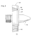
- Figure 3 illustrates a perspective top elevational view of a further embodiment of a heat sealer.
- FIG. 1 illustrates an embodiment of a heat sealer 10.
- the heat sealer 10 functions to attach a fitment 13 to a web of film 20. This allows one in a form, fill and seal packaging machine to create a container having a fitment 13.
- form, fill and seal packaging machine means packaging machines for creating from a web of film a container that houses a product.
- the heat sealer 10 is designed to be preferably utilized with the apparatus and method for attaching a fitment to a web of film described in EP-A-0210259.
- the disclosure of EP-A-0210259 is incorporated herein by reference.
- the heat sealer 10 includes a threaded portion 11 that is designed to be received within a heat seal block 12 that includes a cartridge heater (not illustrated) and thermocouple (not illustrated).
- the heat seal block 12 is then secured to a support block on the fill tube as described in U.S. Patent Application No. 697,534.
- the heat sealer 10 includes a heat seal tip 32 and an abutment member 34.
- the abutment member 34 includes a face 36.
- the face 36 of the abutment member 34 includes a flat lower region 35 and a flat raised region 37.
- the raised region 37 insures that a strong heat seal is created between the fitment 13 and the web of film 20 across the entire surface of the flange 14 of the fitment.
- the raised region 37 compensates for the flexing of the fitment 13 as the web of film 20 is sealed to the fitment 13.
- the raised region 37 extends from the lower portion 35 of the face 36 of the abutment member 34 by approximately 0.0254 mm to about 0.381 mm (1/1000 to about 15/1000 of an inch) and most preferably extends by approximately 0.127 mm (5/1000 of an inch).
- the raised region 37 is desirable in that, due to the increased height of the raised region 37, the web of film 20 is securely sealed to the flange 14 of the fitment 13.
- the raised region 37 preferably has a circumference equal to that portion of the flange 14 of the fitment 13 that is not backed up by the elastomeric back-up member 50 of the heat seal press head 41.
- the heat seal press head 41 functions to urge the fitment 13 towards the web of film 20 and thereby the heat sealer 10. Due to the construction of the fitment 13, the portion of the fitment 13 that is not backed up by the back-up member 50 has sufficient structural rigidity and therefore does not need the back-up member 50 supporting it.
- the heat seal tip 32 includes an elongated body 38 and point 40.
- the point 40 has a conical shape.
- the angle of the vertex of the point 40 is between approximately 40 to about 55 degrees.
- the angle of the vertex is approximately 45 degrees.
- the point 40 is radiused off to insure that it is not too sharp.
- the length of the heat sealer can be an important dimension.
- the length of the heat sealer 10 from its back portion 31 to the tip 40 is approximately 13.97 to about 16.51 mm (550/1000 to about 650/1000 of an inch) for a web of film with a thickness of approximately 100 microns to about 200 microns.
- the heat sealer 10 is constructed from a metal, e.g., aluminum. It has been found that 6061 aluminum functions satisfactorily.
- the aluminum is bright polished and coated with an anodized teflon impregnated coating.
- An anodized teflon impregnated coating sold under the name Nituff by Nimet Industries has been found to function satisfactorily.
- the teflon coating provides a better wear for the heat sealer 10 and also provides a surface that can be easily cleaned of the plastic buildup. Moreover, the coating prevents denting of the heat sealer 10.
- the heat sealer 10 includes flats 60.
- the flats 60 provide a means to aid the user in removing the heat sealer 10 from the heat seal block. Because the heat sealer 10 is heated during use, the threads 11 may deform due to the heat. Accordingly it may be difficult to remove the heat sealer 10 from the heat seal block.
- the flats 60 provide a means for utilizing a mechanical advantage to remove the heat sealer 10.
- the elongated body 38 of the heat seal tip 32 has an outer diameter that is approximately 0.0508 mm (.002 inches) to about 0.1016 mm (.004 inches) larger than the inner diameter of the opening in the fitment 13. This can be an important dimension because if the diameter is too large the heat seal tip 32 will be difficult to remove from the shaft of the fitment 13 after the web of film 20 has been sealed to the fitment. If the outer diameter of the heat seal tip 32 is too small then it will be difficult to get proper alignment with respect to the fitment 13 and web of film 20.
- the heat sealer 10 includes a radius 61 and undercut 62.
- the radius 61 and undercut 62 prevent draping of the film 13 as it is sealed to the fitment 13. Without the radius 61 and undercut 62 the film 20 can be pushed down around the side of the abutment member 34 by the back-up member 50 causing the film to weaken at this point.
- the radius 61 and undercut 62 function to radius away the film 20 from contact with the heat sealer 10.
- the radius 61 has a cross-sectional width of approximately 0.508 to about 0.889 mm (20/1000 to about 35/1000 of an inch). It has been found that if the radius has a thickness of approximately 0.6858 mm (27/1000 of an inch) it functions satisfactorily.
- the undercut 63 is between approximately 0.254 to about 0.762 mm (10/1000 to about 30/1000 of an inch) deep. It has been found that if the undercut is approximately 0.508 mm (20/1000 of an inch) deep it functions satisfactorily.
- FIG. 3 illustrates another embodiment of a heat sealer 110.
- the heat sealer 110 includes a heat seal tip 132 and an abutment member 134 that includes a face 136.
- the face 136 includes a raised region 137 and a lower region 135.
- the raised region 137 has dimensions that are similar to those of the raised region 37 of the heat sealer 10 previously disclosed.
- the lower region 135 may include a groove 150.
- the groove 150 functions to provide a means for allowing air that is entrapped during the sealing process between the face 135 of the heat sealer 10 and the web of film 20 to escape.
- the groove 150 is located between approximately 1.27 to about 1.778 mm (50/1000 to about 70/1000 of the inch) from the circumferential edge of the face 136.
- the groove 150 is located 1,524 mm (60/1000 of an inch) from the circumferential edge of the face 136. It has been found that a groove 150 with a depth of approximately 0.0254 mm (1/1000 of an inch) and a width of 0.0254 mm (1/1000 of an inch) functions satisfactorily.
Landscapes
- Engineering & Computer Science (AREA)
- Mechanical Engineering (AREA)
- Lining Or Joining Of Plastics Or The Like (AREA)
- Making Paper Articles (AREA)
- Package Closures (AREA)
- Auxiliary Devices For And Details Of Packaging Control (AREA)
- Containers And Plastic Fillers For Packaging (AREA)
Abstract
Description
- The present invention relates to an apparatus for attaching a fitment to a web of film. In particular, the present invention relates to an improved apparatus for piercing and sealing a web of film to a fitment.
- In some types of packaging arts including, inter alia, pharmaceutical, food products, and dairy products, it is desirable to make flexible containers that include means for accessing the container (hereinafter "fitments"). As used herein, the term fitment includes, without limitation, valves, ports, port enclosure assemblies, and other means for accessing a container. Fitments provide ports for establishing fluid communication between the container and the outside environment. An example of a container utilizing a fitment is the VIAFLEX® flexible container for parenteral solutions produced by Travenol Laboratories, Inc. of Deerfield, Illinois.
- Flexible containers with fitments may be produced by form, fill and seal packaging machines. Form, fill and seal packaging machines provide an apparatus for forming a web of film into a flexible container housing a desired product. Typically, these machines include a former or mandrel, a fill tube, and heat sealers. The former or mandrel forms the web of film into a tubular shape around the fill or film tube. The fill tube is utilized to dispense the material to be packaged into the tubular shaped web of film.
- In one type of form, fill and seal packaging machine, the fitments are attached via an impulse heat sealing system. Usually impulse heat sealing systems utilize a ring heating element that has a shape substantially similar to the flange portion of the fitment. In an impulse type system, the ring member is not constantly heated but rather, heated for a sufficient length of time to provide the ring member with enough heat energy to cause the web of film to melt and fusion seal to the fitment flange.
- Depending upon its end use, the web of film, to which the fitment is attached, may or may not include a prepierced hole. In the typical "bag in a box" design, the film is typically prepierced. To this end, the web of film is prepierced and the fitment is located over the prepierced hole so that there is fluid communication between the fitment and the container. The prior art has also utilized a method of passing a fitment through the prepierced hole. Both these methods require that the fitment is located with precision over, or in, the prepierced hole, slowing down the production of the flexible containers.
- EP-A-0210259, which conforms to Art. 54(3)EPC, discloses an apparatus for contemporaneously piercing and sealing the web of film to the fitment. The present invention provides an improved apparatus for piercing and sealing the web of film to the fitment.
- The present invention provides an apparatus for piercing a web of film and sealing the web of film to a fitment having a main portion and a flange, the apparatus comprising an abutment member including a heated face which holds the web of film in contact with the flange during sealing, characterised in that the heated face has lower and raised flat regions both for holding the web of film in contact with the flange and further characterised by a heat seal tip extending from the raised region for piercing the web of film
An advantage of the present invention is that the apparatus for piercing and sealing the web of film produces a strong heat seal between the web of film and the fitment. - Moreover, an advantage of the present invention is that the heat sealer of the present invention produces an effective heat seal on the flange of the fitment.
- Furthermore, an advantage of the present invention is that the heat sealer can utilize lower heat seal temperatures.
- The heat sealer may include a radius and undercut to prevent draping of the film.
- The heat sealer may include a groove to prevent air entrapment between the heat sealer and the web of film.
- The heat sealer may include flats to improve the ability of the user to remove the heat sealer from the heat seal block.
- Additional features and advantages are described in, and will be apparent from, the detailed description of the presently preferred embodiments and from the drawings.
- Figure 1 illustrates a side elevational view of an apparatus for piercing and sealing.
- Figure 2 illustrates a perspective view of the heat sealer of Figure 1.
- Figure 3 illustrates a perspective top elevational view of a further embodiment of a heat sealer.
- Figure 1 illustrates an embodiment of a
heat sealer 10. Theheat sealer 10 functions to attach afitment 13 to a web offilm 20. This allows one in a form, fill and seal packaging machine to create a container having afitment 13. As used herein, the term "form, fill and seal packaging machine" means packaging machines for creating from a web of film a container that houses a product. - The
heat sealer 10 is designed to be preferably utilized with the apparatus and method for attaching a fitment to a web of film described in EP-A-0210259. The disclosure of EP-A-0210259 is incorporated herein by reference. - To this end, as illustrated in Figure 1 and 2, the
heat sealer 10 includes a threadedportion 11 that is designed to be received within a heat seal block 12 that includes a cartridge heater (not illustrated) and thermocouple (not illustrated). The heat seal block 12 is then secured to a support block on the fill tube as described in U.S. Patent Application No. 697,534. - Referring to Figure 2, the
heat sealer 10 includes aheat seal tip 32 and anabutment member 34. Theabutment member 34 includes aface 36. As illustrated, theface 36 of theabutment member 34 includes a flatlower region 35 and a flat raisedregion 37. - The raised
region 37 insures that a strong heat seal is created between thefitment 13 and the web offilm 20 across the entire surface of theflange 14 of the fitment. The raisedregion 37 compensates for the flexing of thefitment 13 as the web offilm 20 is sealed to thefitment 13. - Preferably the raised
region 37 extends from thelower portion 35 of theface 36 of theabutment member 34 by approximately 0.0254 mm to about 0.381 mm (1/1000 to about 15/1000 of an inch) and most preferably extends by approximately 0.127 mm (5/1000 of an inch). The raisedregion 37 is desirable in that, due to the increased height of the raisedregion 37, the web offilm 20 is securely sealed to theflange 14 of thefitment 13. - The raised
region 37 preferably has a circumference equal to that portion of theflange 14 of thefitment 13 that is not backed up by the elastomeric back-upmember 50 of the heat seal press head 41. As discussed in detail in EP-A-0210259, the heat seal press head 41 functions to urge thefitment 13 towards the web offilm 20 and thereby theheat sealer 10. Due to the construction of thefitment 13, the portion of thefitment 13 that is not backed up by the back-upmember 50 has sufficient structural rigidity and therefore does not need the back-upmember 50 supporting it. - The
heat seal tip 32 includes anelongated body 38 andpoint 40. Preferably thepoint 40 has a conical shape. Preferably the angle of the vertex of thepoint 40 is between approximately 40 to about 55 degrees. Preferably the angle of the vertex is approximately 45 degrees. Preferably thepoint 40 is radiused off to insure that it is not too sharp. - The length of the heat sealer can be an important dimension. Preferably the length of the
heat sealer 10 from its back portion 31 to thetip 40 is approximately 13.97 to about 16.51 mm (550/1000 to about 650/1000 of an inch) for a web of film with a thickness of approximately 100 microns to about 200 microns. - Preferably the
heat sealer 10 is constructed from a metal, e.g., aluminum. It has been found that 6061 aluminum functions satisfactorily. Preferably the aluminum is bright polished and coated with an anodized teflon impregnated coating. An anodized teflon impregnated coating sold under the name Nituff by Nimet Industries has been found to function satisfactorily. The teflon coating provides a better wear for theheat sealer 10 and also provides a surface that can be easily cleaned of the plastic buildup. Moreover, the coating prevents denting of theheat sealer 10. - Preferably, the
heat sealer 10 includesflats 60. Theflats 60 provide a means to aid the user in removing theheat sealer 10 from the heat seal block. Because theheat sealer 10 is heated during use, thethreads 11 may deform due to the heat. Accordingly it may be difficult to remove theheat sealer 10 from the heat seal block. Theflats 60 provide a means for utilizing a mechanical advantage to remove theheat sealer 10. - Preferably, the
elongated body 38 of theheat seal tip 32 has an outer diameter that is approximately 0.0508 mm (.002 inches) to about 0.1016 mm (.004 inches) larger than the inner diameter of the opening in thefitment 13. This can be an important dimension because if the diameter is too large theheat seal tip 32 will be difficult to remove from the shaft of thefitment 13 after the web offilm 20 has been sealed to the fitment. If the outer diameter of theheat seal tip 32 is too small then it will be difficult to get proper alignment with respect to thefitment 13 and web offilm 20. - Preferably, the
heat sealer 10 includes aradius 61 and undercut 62. Theradius 61 and undercut 62 prevent draping of thefilm 13 as it is sealed to thefitment 13. Without theradius 61 and undercut 62 thefilm 20 can be pushed down around the side of theabutment member 34 by the back-upmember 50 causing the film to weaken at this point. Theradius 61 and undercut 62 function to radius away thefilm 20 from contact with theheat sealer 10. Preferably, theradius 61 has a cross-sectional width of approximately 0.508 to about 0.889 mm (20/1000 to about 35/1000 of an inch). It has been found that if the radius has a thickness of approximately 0.6858 mm (27/1000 of an inch) it functions satisfactorily. Preferably the undercut 63 is between approximately 0.254 to about 0.762 mm (10/1000 to about 30/1000 of an inch) deep. It has been found that if the undercut is approximately 0.508 mm (20/1000 of an inch) deep it functions satisfactorily. - Figure 3 illustrates another embodiment of a
heat sealer 110. As illustrated, theheat sealer 110 includes aheat seal tip 132 and anabutment member 134 that includes aface 136. Theface 136 includes a raisedregion 137 and alower region 135. Preferably, the raisedregion 137 has dimensions that are similar to those of the raisedregion 37 of theheat sealer 10 previously disclosed. - The
lower region 135 may include agroove 150. Thegroove 150 functions to provide a means for allowing air that is entrapped during the sealing process between theface 135 of theheat sealer 10 and the web offilm 20 to escape. Preferably thegroove 150 is located between approximately 1.27 to about 1.778 mm (50/1000 to about 70/1000 of the inch) from the circumferential edge of theface 136. Most preferably, thegroove 150 is located 1,524 mm (60/1000 of an inch) from the circumferential edge of theface 136. It has been found that agroove 150 with a depth of approximately 0.0254 mm (1/1000 of an inch) and a width of 0.0254 mm (1/1000 of an inch) functions satisfactorily.
Claims (8)
- An apparatus for piercing a web of film (20) and sealing the web of film (20) to a fitment (13) having a main portion and a flange (14), the apparatus comprising an abutment member (34,134) including a heated face (36,136) which holds the web of film (20) in contact with the flange (14) during sealing, characterised in that the heated face (36,136) has lower and raised flat regions (35,135; 37,137) both for holding the web of film in contact with the flange (14) and further characterised by a heat seal tip (32,132) extending from the raised region (37,137) for piercing the web of film (20)
- Apparatus according to Claim 1 in combination with a fitment (13) and a press head (41), the press head (41) being located on the opposite side of the web of film (20) to said heat seal tip (32,132) for urging the fitment (13) towards the web of film (20), the fitment press head (41) having a backup member (50) for backing up a portion of the flange (14) of the fitment (13); the raised region (37) of the heated face having a circumference substantially equal to a circumference of a portion of the flange (14) not backed up by the backup member (50).
- The apparatus of Claim 1 or 2 wherein the heated face (136) includes a groove (150) for releasing entrapped air.
- The apparatus of Claim 3 wherein the groove (150) is positioned in said lower region (135).
- The apparatus of Claim 1, 2, 3 or 4 wherein means for attaching the apparatus to heating means is provided comprising a threaded screw (11) extending from the back of the abutment member (34,134).
- The apparatus of Claim 5 comprising flats (60) circumscribing a portion of the outer circumference of the abutment member for aiding in the removal of the apparatus from the heating means.
- The apparatus of any preceding claim wherein the angle of the vertex of the heat seal tip is approximately 40 to about 55 degrees.
- The apparatus of any preceding claim including a radius (61) circumscribing the heated face and defined by an undercut (62) for preventing draping of the film.
Applications Claiming Priority (2)
| Application Number | Priority Date | Filing Date | Title |
|---|---|---|---|
| US81964886A | 1986-01-17 | 1986-01-17 | |
| US819648 | 1986-01-17 |
Publications (3)
| Publication Number | Publication Date |
|---|---|
| EP0255540A1 EP0255540A1 (en) | 1988-02-10 |
| EP0255540A4 EP0255540A4 (en) | 1990-06-28 |
| EP0255540B1 true EP0255540B1 (en) | 1993-10-27 |
Family
ID=25228687
Family Applications (1)
| Application Number | Title | Priority Date | Filing Date |
|---|---|---|---|
| EP87901175A Expired - Lifetime EP0255540B1 (en) | 1986-01-17 | 1987-01-13 | An apparatus for attaching a fitment to a web of film |
Country Status (6)
| Country | Link |
|---|---|
| EP (1) | EP0255540B1 (en) |
| JP (1) | JPH0777759B2 (en) |
| AU (1) | AU606048B2 (en) |
| CA (1) | CA1290534C (en) |
| DE (1) | DE3787936T2 (en) |
| WO (1) | WO1987004391A1 (en) |
Families Citing this family (1)
| Publication number | Priority date | Publication date | Assignee | Title |
|---|---|---|---|---|
| US5419800A (en) * | 1994-01-27 | 1995-05-30 | The United States Of America As Represented By The Secretary Of The Navy | Split gasket attachment strip |
Family Cites Families (8)
| Publication number | Priority date | Publication date | Assignee | Title |
|---|---|---|---|---|
| US3069303A (en) * | 1960-02-05 | 1962-12-18 | Scholle Chemical Corp | Process and apparatus for producing flexible containers |
| US3159695A (en) * | 1960-10-17 | 1964-12-01 | Bahlsen Werner | Process for pneumatic formation of thermoplastic foils |
| US3244576A (en) * | 1963-02-04 | 1966-04-05 | Thermoplastic Ind Inc | Apparatus for manufacturing flexible bags with nozzle |
| FR1482760A (en) * | 1965-08-17 | 1967-05-26 | Pfaff Ag G M | High frequency welding device, for forming buttonholes in fabrics or knits made of synthetic textiles |
| US3434908A (en) * | 1965-11-12 | 1969-03-25 | Summerhayes Holdings Ltd | Sealing head |
| US3760563A (en) | 1971-12-13 | 1973-09-25 | G Zimmermann | Drawing apparatus for sealing containers |
| US4246062A (en) * | 1979-03-26 | 1981-01-20 | Christine William C | Apparatus for attaching a fitment to a pouch |
| US4695337A (en) * | 1985-02-01 | 1987-09-22 | Baxter Travenol Laboratories, Inc. | Apparatus and method for attaching a fitment to a web of film |
-
1987
- 1987-01-13 AU AU69307/87A patent/AU606048B2/en not_active Expired
- 1987-01-13 WO PCT/US1987/000076 patent/WO1987004391A1/en not_active Ceased
- 1987-01-13 DE DE3787936T patent/DE3787936T2/en not_active Expired - Fee Related
- 1987-01-13 JP JP62501039A patent/JPH0777759B2/en not_active Expired - Fee Related
- 1987-01-13 EP EP87901175A patent/EP0255540B1/en not_active Expired - Lifetime
- 1987-01-16 CA CA000527525A patent/CA1290534C/en not_active Expired - Lifetime
Also Published As
| Publication number | Publication date |
|---|---|
| JPS63503216A (en) | 1988-11-24 |
| EP0255540A1 (en) | 1988-02-10 |
| AU6930787A (en) | 1987-08-14 |
| CA1290534C (en) | 1991-10-15 |
| EP0255540A4 (en) | 1990-06-28 |
| DE3787936D1 (en) | 1993-12-02 |
| WO1987004391A1 (en) | 1987-07-30 |
| DE3787936T2 (en) | 1994-05-26 |
| JPH0777759B2 (en) | 1995-08-23 |
| AU606048B2 (en) | 1991-01-31 |
Similar Documents
| Publication | Publication Date | Title |
|---|---|---|
| US5203819A (en) | Apparatus for attaching a fitment to a web of film | |
| EP0210259B1 (en) | Apparatus and method for attaching a fitment to a web of film | |
| US5348525A (en) | Method of constructing flexible containers with tubular fitments | |
| US5102485A (en) | Apparatus for continuous feeding and synchronized application of fitments to carton blanks and related method | |
| JP2779501B2 (en) | Film guidance system | |
| US4598529A (en) | Method and apparatus for forming, filling and sealing flexible plastic bags | |
| EP0688720B1 (en) | Method and apparatus for manufacturing a container with a tubular label thereon | |
| CA2134921C (en) | Apparatus and process for positioning a fitment | |
| US4250798A (en) | Method of and device for fabricating plastic sleeves | |
| EP1182144A1 (en) | Fitment for spouted pouch | |
| CA1088408A (en) | Method for the manufacture of packing containers and an arrangement for the carrying out of the method | |
| EP0547592B1 (en) | Inertial welded cylinder and method of making same | |
| CA1290534C (en) | Apparatus for attaching a fitment to a web of film | |
| US5714023A (en) | Method for sealing two compartment containers | |
| BR102022014359A2 (en) | REINFORCING RING FOR CAPSULES TO OBTAIN BEVERAGES, CAPSULES TO OBTAIN BEVERAGES, AND METHODS FOR PRODUCING A CAPSULE AND BEVERAGES BY MEANS OF A SYSTEM | |
| ATE76614T1 (en) | FILLING STATION FOR A CARTRIDGE FILLING AND SEALING MACHINE. | |
| JPH11507255A (en) | Multipurpose bottle for subcutaneous dosing and drug dispensing systems | |
| JP4526624B2 (en) | Packaging apparatus and packaging method | |
| US4357746A (en) | Stud for brake booster | |
| JPH03184830A (en) | Ultrasonic wave fusion-bonding method of high-melting resin | |
| JPS6144510B2 (en) | ||
| US4394209A (en) | Arrangement for affixing the bottom of a thermoplastic container | |
| JPH0159161B2 (en) | ||
| JPH0479298B2 (en) | ||
| JPH0579563B2 (en) |
Legal Events
| Date | Code | Title | Description |
|---|---|---|---|
| PUAI | Public reference made under article 153(3) epc to a published international application that has entered the european phase |
Free format text: ORIGINAL CODE: 0009012 |
|
| 17P | Request for examination filed |
Effective date: 19870915 |
|
| AK | Designated contracting states |
Kind code of ref document: A1 Designated state(s): BE CH DE FR GB LI SE |
|
| RAP1 | Party data changed (applicant data changed or rights of an application transferred) |
Owner name: BAXTER INTERNATIONAL INC. (A DELAWARE CORPORATION) |
|
| A4 | Supplementary search report drawn up and despatched |
Effective date: 19900628 |
|
| 17Q | First examination report despatched |
Effective date: 19920630 |
|
| GRAA | (expected) grant |
Free format text: ORIGINAL CODE: 0009210 |
|
| AK | Designated contracting states |
Kind code of ref document: B1 Designated state(s): BE CH DE FR GB LI SE |
|
| REF | Corresponds to: |
Ref document number: 3787936 Country of ref document: DE Date of ref document: 19931202 |
|
| ET | Fr: translation filed | ||
| PLBE | No opposition filed within time limit |
Free format text: ORIGINAL CODE: 0009261 |
|
| STAA | Information on the status of an ep patent application or granted ep patent |
Free format text: STATUS: NO OPPOSITION FILED WITHIN TIME LIMIT |
|
| 26N | No opposition filed | ||
| EAL | Se: european patent in force in sweden |
Ref document number: 87901175.7 |
|
| REG | Reference to a national code |
Ref country code: GB Ref legal event code: IF02 |
|
| PGFP | Annual fee paid to national office [announced via postgrant information from national office to epo] |
Ref country code: FR Payment date: 20050117 Year of fee payment: 19 |
|
| PGFP | Annual fee paid to national office [announced via postgrant information from national office to epo] |
Ref country code: SE Payment date: 20050120 Year of fee payment: 19 |
|
| PGFP | Annual fee paid to national office [announced via postgrant information from national office to epo] |
Ref country code: CH Payment date: 20050124 Year of fee payment: 19 |
|
| PGFP | Annual fee paid to national office [announced via postgrant information from national office to epo] |
Ref country code: DE Payment date: 20050228 Year of fee payment: 19 |
|
| PGFP | Annual fee paid to national office [announced via postgrant information from national office to epo] |
Ref country code: BE Payment date: 20050303 Year of fee payment: 19 |
|
| PGFP | Annual fee paid to national office [announced via postgrant information from national office to epo] |
Ref country code: GB Payment date: 20060104 Year of fee payment: 20 |
|
| PG25 | Lapsed in a contracting state [announced via postgrant information from national office to epo] |
Ref country code: SE Free format text: LAPSE BECAUSE OF NON-PAYMENT OF DUE FEES Effective date: 20060114 |
|
| PG25 | Lapsed in a contracting state [announced via postgrant information from national office to epo] |
Ref country code: CH Free format text: LAPSE BECAUSE OF NON-PAYMENT OF DUE FEES Effective date: 20060131 Ref country code: FR Free format text: LAPSE BECAUSE OF NON-PAYMENT OF DUE FEES Effective date: 20060131 Ref country code: BE Free format text: LAPSE BECAUSE OF NON-PAYMENT OF DUE FEES Effective date: 20060131 Ref country code: LI Free format text: LAPSE BECAUSE OF NON-PAYMENT OF DUE FEES Effective date: 20060131 |
|
| PG25 | Lapsed in a contracting state [announced via postgrant information from national office to epo] |
Ref country code: DE Free format text: LAPSE BECAUSE OF NON-PAYMENT OF DUE FEES Effective date: 20060801 |
|
| REG | Reference to a national code |
Ref country code: CH Ref legal event code: PL |
|
| EUG | Se: european patent has lapsed | ||
| REG | Reference to a national code |
Ref country code: FR Ref legal event code: ST Effective date: 20060929 |
|
| PG25 | Lapsed in a contracting state [announced via postgrant information from national office to epo] |
Ref country code: GB Free format text: LAPSE BECAUSE OF EXPIRATION OF PROTECTION Effective date: 20070112 |
|
| REG | Reference to a national code |
Ref country code: GB Ref legal event code: PE20 |
|
| BERE | Be: lapsed |
Owner name: *BAXTER INTERNATIONAL INC. (A DELAWARE CORP.) Effective date: 20060131 |