EP0255107B1 - Program mode setting apparatus - Google Patents
Program mode setting apparatus Download PDFInfo
- Publication number
- EP0255107B1 EP0255107B1 EP87110917A EP87110917A EP0255107B1 EP 0255107 B1 EP0255107 B1 EP 0255107B1 EP 87110917 A EP87110917 A EP 87110917A EP 87110917 A EP87110917 A EP 87110917A EP 0255107 B1 EP0255107 B1 EP 0255107B1
- Authority
- EP
- European Patent Office
- Prior art keywords
- vps
- recording
- code
- program
- circuit
- Prior art date
- Legal status (The legal status is an assumption and is not a legal conclusion. Google has not performed a legal analysis and makes no representation as to the accuracy of the status listed.)
- Expired - Lifetime
Links
- 230000004044 response Effects 0.000 claims description 16
- 230000000994 depressogenic effect Effects 0.000 description 4
- 238000010586 diagram Methods 0.000 description 4
- 238000001514 detection method Methods 0.000 description 3
- 230000003247 decreasing effect Effects 0.000 description 2
- 230000000881 depressing effect Effects 0.000 description 1
Images


Classifications
-
- H—ELECTRICITY
- H04—ELECTRIC COMMUNICATION TECHNIQUE
- H04N—PICTORIAL COMMUNICATION, e.g. TELEVISION
- H04N7/00—Television systems
- H04N7/08—Systems for the simultaneous or sequential transmission of more than one television signal, e.g. additional information signals, the signals occupying wholly or partially the same frequency band, e.g. by time division
- H04N7/087—Systems for the simultaneous or sequential transmission of more than one television signal, e.g. additional information signals, the signals occupying wholly or partially the same frequency band, e.g. by time division with signal insertion during the vertical blanking interval only
- H04N7/088—Systems for the simultaneous or sequential transmission of more than one television signal, e.g. additional information signals, the signals occupying wholly or partially the same frequency band, e.g. by time division with signal insertion during the vertical blanking interval only the inserted signal being digital
- H04N7/0887—Systems for the simultaneous or sequential transmission of more than one television signal, e.g. additional information signals, the signals occupying wholly or partially the same frequency band, e.g. by time division with signal insertion during the vertical blanking interval only the inserted signal being digital for the transmission of programme or channel identifying signals
-
- H—ELECTRICITY
- H04—ELECTRIC COMMUNICATION TECHNIQUE
- H04N—PICTORIAL COMMUNICATION, e.g. TELEVISION
- H04N5/00—Details of television systems
- H04N5/76—Television signal recording
- H04N5/78—Television signal recording using magnetic recording
- H04N5/782—Television signal recording using magnetic recording on tape
-
- Y—GENERAL TAGGING OF NEW TECHNOLOGICAL DEVELOPMENTS; GENERAL TAGGING OF CROSS-SECTIONAL TECHNOLOGIES SPANNING OVER SEVERAL SECTIONS OF THE IPC; TECHNICAL SUBJECTS COVERED BY FORMER USPC CROSS-REFERENCE ART COLLECTIONS [XRACs] AND DIGESTS
- Y10—TECHNICAL SUBJECTS COVERED BY FORMER USPC
- Y10S—TECHNICAL SUBJECTS COVERED BY FORMER USPC CROSS-REFERENCE ART COLLECTIONS [XRACs] AND DIGESTS
- Y10S358/00—Facsimile and static presentation processing
- Y10S358/908—Pause control, i.e. "commercial killers"
Definitions
- the present invention relates to a record mode setting apparatus for controlling program recording operation by recording means in response to a VPS code multiplexed on a broadcasting signal.
- VPS video program system
- the VPS is adapted such that timer recording of the video tape recorder can be controlled on the side of a broadcasting station when the broadcasting station superposes on a video signal a digitized code (VPS code) for identifying a program and broadcasts the same.
- VPS is disclosed in detail in for instance DE-A-2950432 and DE-A-3243610.
- Preset program information is inputted to a preset program storing circuit 6 by operation of a program preset button group 4.
- the preset program storing circuit 6 stores the preset program information as a preset program code and provides the same to display means 9, so that the display means displays the information.
- the preset program code includes a starting time code concerning the starting time point of recording, a channel code concerning a preset program channel, and an ending time code concerning the ending time point of recording (or a recording time period).
- the preset program storing circuit 6 also stores the set state of a VPS setting switch 5 for selecting a program preset mode.
- the program preset mode is set to a VPS program preset mode by turning the VPS setting switch 5 on and set to a normal program preset mode by turning the VPS setting switch 5 off.
- a program is recorded in response to a VPS code multiplexed on a video signal independently of the starting time of recording and the ending time of recording as represented by the preset program code.
- the program is recorded from the starting time of recording to the ending time of recording in accordance with the actual time.
- the VPS code includes at least a program code showing the predicted starting time of a program.
- a before-three hours determining circuit 13 compares real-time information outputted from a clock circuit 11 with the starting time code stored in the preset program storing circuit 6 and starts operating a second power supply circuit 15 three hours, for example, before the starting time recording.
- a tuner 2 is driven.
- a channel selecting circuit 12 inputs a channel code stored in the preset program storing circuit 6 and applies a corresponding tuning voltage to the tuner 2.
- the tuner 2 selects a video signal corresponding to a preset program channel from a broadcasting signal obtained by an antenna 1 an applies the video signal to a VPS decoder 3.
- the VPS decoder 3 starts decoding the VPS code three hours before the starting time of recording and continues to send the same to a code latch circuit 7.
- a preset program coincidence determining circuit 8 compares a program code included in the VPS code stored in the code latch circuit 7 with the starting time code stored in the preset program storing circuit 6 and outputs a coincidence signal when both coincide with each other.
- a timer control circuit 10 operates a first power supply circuit 14 in response to the coincidence signal.
- recording means 16 is driven by the power supply 14, so that recording of the video signal outputted from the tuner 2 is started.
- the recording is performed during a time period when the program code included in the above described VPS code continue to coincide with the starting time code included in the preset program code. Meanwhile, if the above described program code is changed to a code indicating interruption of the program (program interruption code), only the above described first power supply circuit 14 is not operated while the program interruption code is being produced.
- the program code included in the VPS code is changed, so that the coincidence signal is not outputted from the preset program coincidence determining circuit 8, resulting in ending of recording.
- the program preset mode if the time for a desired program is changed and the time for a program is extended, the program can be surely recorded.
- the VPS code is not multiplexed on the video signal, the VPS code is not stored in the above described code latch circuit 7.
- the preset program coincidence determining circuit 8 determines that the VPS code is not stored in the code latch circuit 7, recording is performed in the normal program preset mode.
- the preset program coincidence determining circuit 8 compares the real-time information outputted from the clock circuit 11 with the starting time code stored in the preset program storing circuit 6 and outputs the coincidence signal when both coincide with each other.
- the timer control circuit 10 operates the first power supply circuit 14 and the second power supply circuit 15 in response to the coincidence signal. As a result, at the starting time of recording, recording is started. After recording is started, the preset program coincidence determining circuit 8 compares the real-time information outputted from the clock circuit 11 with the ending time code stored in the preset program storing circuit 6 and outputs the coincidence signal when both coincide with each other.
- the timer control circuit 10 stops operation of the first power supply circuit 14 and the second power supply circuit 15 in response to the coincidence signal and ends recording by recording means 16. Even if the VPS code is multiplexed on the video signal corresponding to the preset program channel, recording is performed in the above described normal program preset mode irrespective of the contents stored in the code latch circuit 7 if the VPS setting switch 5 is set to the off state at the time of program presetting operation.
- Fig. 1 the portion 20 enclosed by a broken line is structured by a microcomputer.
- a video tape recorder comprising the above described record mode setting apparatus can perform not only the above described normal preset program recording but also manual recording.
- the above described conventional record mode setting apparatus can not control recording based on the VPS code in the case of recording by normal manual operation, so that a user can not surely record a desired program if a user does not continue to monitor the program until the program is ended.
- a primary object of the present invention is to provide a record mode setting apparatus capable of performing recording based on a VPS code even in the case of recording by manual operation.
- the record mode setting apparatus further comprises an inverting switch means and VPS mode switching means, said VPS mode switching means preventing said control signal from being supplied from said VPS control means to said recording means in response to operation of said inverting switch.
- An advantage of the record mode setting apparatus is that recording based on the VPS code is possible even in the case of recording by manual operation, and a desired program can be precisely recorded even if the program does not continue to be monitored during recording.
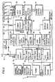
- Figs. 2 and 3 are block diagrams showing a record mode setting apparatus according to an embodiment of the present invention.
- the record mode setting apparatus can perform recording by manual operation and preset program recording. A portion for performing recording by manual operation is shown in Fig. 2, and a portion for performing preset program recording is shown in Fig. 3.
- Figs. 2 and 3 portions appended by the identical reference numerals indicate the identical portions.
- Recording by manual operation is performed in either a normal record mode or a VPS record mode
- preset program recording is performed in either a normal program preset mode or a VPS program preset mode.
- a channel selecting circuit 12 applies a tuning voltage corresponding to the channel to a tuner 2.
- the tuner 2 selects a video signal corresponding to the above described channel from a broadcasting signal obtained by an antenna 1 and applies the video signal to recording means 16.
- the video signal obtained by the tuner 2 is also applied to a VPS decoder 3.
- the VPS decoder 3 derives a VPS signal from the video signal and detects a VPS code from it and applies the VPS code to a VPS code determining circuit 23, a code latch circuit 7 and a code memory 27.
- the VPS code determining circuit 23 determines whether or not the VPS code is multiplexed on the video signal and applies a code detection signal to a VPS mode setting circuit 22 if the VPS code is applied from the VPS decoder 3. More specifically, when a channel in which the VPS code is not multiplexed on the video signal is selected, the VPS code determining circuit 23 does not generate the code detection signal.
- VPS setting switch 41 When a VPS setting switch 41 which is normally opened is closed, an output from the VPS setting switch 41 is applied to a holding circuit 25 as a VPS set signal.
- the holding circuit 25 holds the VPS set signal during a constant time period, and an output from the holding circuit 25 is applied to the VPS mode setting circuit 22. If the recording set signal from the system control circuit 33 and the code detection signal from the VPS code determining circuit 23 are generated while an output from the above described holding circuit 25 is produced, the VPS mode setting circuit 22 outputs a VPS recording set signal.
- the VPS mode setting circuit 22 determines that a VPS record mode can be set and generates the VPS recording set signal in response to setting of the VPS setting switch 41. Therefore, if the record switch 53 is operated within a holding time period of the VPS set signal after operation of the VPS setting switch 41, VPS recording can be set.
- the VPS recording set signal is applied to a lock gate control circuit 24, a VPS control circuit 26, a write pulse generating circuit 28 and display means 9.
- the lock gate control circuit 24 applies a lock control signal to the lock gate 31 in response to the VPS recording set signal.
- the lock gate 31 prevents subsequent passage of a command signal from each of operation switches 51 to 57 and makes manual control of the recording means 16 impossible.
- the write pulse generating circuit 28 generates a write pulse in response to the above described VPS recording set signal.
- the code memory 27 stores the VPS code detected by the VPS decoder 3 in response to the write pulse. More specifically, the code memory 27 stores the VPS code at the time of VPS setting operation.
- the display means 9 displays an indication that a record mode is set to the VPS record mode in response to the above described VPS recording set signal.
- a code latch circuit 7 repeats latching operation of the VPS code detected by the VPS decoder 3.
- the VPS control circuit 26 compares the VPS code latched by the code latch circuit 7 with the VPS code stored in the code memory 27, and applies a signal based on the result of comparison to the mode setting circuit 32 through a VPS mode switching circuit 30.
- the VPS control circuit 26 outputs a stop command signal.
- the mode setting circuit 32 commands the system control circuit 33 to stop the recording means 16 in response to the stop command signal.
- the system control circuit 33 makes the recording means 16 ready for stopping.
- the VPS control circuit 26 When the VPS code latched by the code latch circuit 7 is changed again to the original program code, the VPS control circuit 26 outputs a recording command signal, so that the recording means 16 is ready for recording again. In addition, when the VPS code latched by the code latch circuit 7 is changed to a different program code from the VPS code stored in the code memory 27, the VPS control circuit 26 outputs a recording ending command signal.
- the mode setting circuit 32 commands the system control circuit 33 to end recording operation of the recording means 16 in response to the recording ending command signal. Therefore, the system control circuit 33 ends recording operation by the recording means 16.
- the record mode is changed from the VPS record mode to the normal record mode by operation of the record mode inverting switch 42. Therefore, a signal applied to the VPS mode switching circuit 30 from the VPS control circuit 26 is not transmitted to the mode setting circuit 32, and the locked state of the lock gate 31 is released by the lock gate control circuit 24. Thus, manual operation of the recording means 16 by a stop switch 51, a playback switch 52, the record switch 53, a pause switch 54, a fast forward switch 55 and a rewind switch 56 becomes possible.
- the record mode inverting switch 42 is operated again, the record mode is changed again from the normal record mode to the VPS record mode, so that recording in the VPS record mode is performed.
- the change of the record mode is displayed by the display means 9.
- the lock gate control circuit 24 is controlled by operation of a lock switching switch 43 which is normally opened.
- the lock switching switch 43 In the VPS record mode, when the lock switching switch 43 is depressed, the lock control signal outputted from the lock gate control circuit 24 is not outputted, so that the locked state of the lock gate 31 is released. Therefore, the recording means 16 can be controlled by operation of the operating switches 51 to 57.
- the lock switching switch 43 if and when it is not desired to record a commercial or the like during recording in the VPS record mode, the lock switching switch 43 is operated and then, the pause switch 54 is operated so that recording can be interrupted.
- the lock gate 31 becomes to be in the original locked state by operating again the lock switching switch 43.
- the locked state and the unlocked state are inverted every time the lock switching switch 43 is operated.
- the state of the lock gate 31 is displayed by the display means 9.
- the record mode inverting switch 42 need not necessarily by separately provided. It is needless to say that the VPS setting switch 41 may be provided with, for example, a decoder so that the VPS mode switching circuit 30 and the display means 9 are controlled every time the VPS setting switch 41 is operated by the decoder.
- the record mode control device recording by a one-touch timer switch 57 is possible.
- the recording time period is stored in a timer circuit 29 in accordance with the number of times of the depression.
- the VPS record mode is automatically set by depressing the one-touch timer switch 57, the VPS set signal is applied from the one-touch timer switch 57 to the VPS mode setting circuit 22, so that recording is started in the VPS record mode in the same manner as when the VPS setting switch 41 is depressed.
- the VPS record mode when the one-touch timer switch 57 is operated, the VPS code detected by the VPS decoder 3 is stored in the code memory 27.
- the VPS code applied to the code latch circuit 7 from the VPS decoder 3 are compared with the VPS code stored in the code memory 27.
- the VPS code applied to the code latch circuit 7 does not coincide with the VPS code stored in the code memory 27 irrespective of the recording time period set by the one-touch timer switch 57, recording is ended.
- a ten key may be provided so that the recording time period is set to the timer circuit 29 by operation of the ten key and counting operation of the timer circuit 29 is started by operation of the one-touch timer switch 57.
- the VPS record mode is changed to the normal record mode by operation of the record mode inverting switch 42.
- the lock gate 31 is locked or disconnected in the initial state immediately after the VPS recording set signal is generated from the VPS mode setting circuit 22, the lock gate 31 may pass signals from the operation switches 51 to 57 in the initial state. In this case, so long as the lock switching switch 43 is not operated, the recording means 16 can be manually controlled.
- the lock switching switch 43, the lock gate control circuit 24 and the lock gate 31 may be omitted.
- the locked states of only signals from the pause switch 54 or only signals from the pause switch 54 and the stop switch 51 may be released by operation of the lock switching switch 43. In this case, only operation for cutting a record such as a commercial becomes possible.
Landscapes
- Engineering & Computer Science (AREA)
- Multimedia (AREA)
- Signal Processing (AREA)
- Television Signal Processing For Recording (AREA)
- Signal Processing Not Specific To The Method Of Recording And Reproducing (AREA)
Description
- The present invention relates to a record mode setting apparatus for controlling program recording operation by recording means in response to a VPS code multiplexed on a broadcasting signal.
- In West Germany, a program presetting system referred to as a VPS (video program system) has been widely used in a video tape recorder. The VPS is adapted such that timer recording of the video tape recorder can be controlled on the side of a broadcasting station when the broadcasting station superposes on a video signal a digitized code (VPS code) for identifying a program and broadcasts the same. The VPS is disclosed in detail in for instance DE-A-2950432 and DE-A-3243610.
- Referring now to Fig. 1, description is made on an example of a conventional record mode setting apparatus using such a VPS.
- Preset program information is inputted to a preset program storing
circuit 6 by operation of a programpreset button group 4. The presetprogram storing circuit 6 stores the preset program information as a preset program code and provides the same to display means 9, so that the display means displays the information. The preset program code includes a starting time code concerning the starting time point of recording, a channel code concerning a preset program channel, and an ending time code concerning the ending time point of recording (or a recording time period). The presetprogram storing circuit 6 also stores the set state of aVPS setting switch 5 for selecting a program preset mode. The program preset mode is set to a VPS program preset mode by turning theVPS setting switch 5 on and set to a normal program preset mode by turning theVPS setting switch 5 off. In the VPS program preset mode, a program is recorded in response to a VPS code multiplexed on a video signal independently of the starting time of recording and the ending time of recording as represented by the preset program code. In the normal program preset mode, the program is recorded from the starting time of recording to the ending time of recording in accordance with the actual time. The VPS code includes at least a program code showing the predicted starting time of a program. - In the VPS program preset mode, a before-three
hours determining circuit 13 compares real-time information outputted from aclock circuit 11 with the starting time code stored in the preset program storingcircuit 6 and starts operating a secondpower supply circuit 15 three hours, for example, before the starting time recording. Thus, atuner 2 is driven. Achannel selecting circuit 12 inputs a channel code stored in the preset program storingcircuit 6 and applies a corresponding tuning voltage to thetuner 2. Thus, thetuner 2 selects a video signal corresponding to a preset program channel from a broadcasting signal obtained by anantenna 1 an applies the video signal to aVPS decoder 3. As a result, theVPS decoder 3 starts decoding the VPS code three hours before the starting time of recording and continues to send the same to acode latch circuit 7. - A preset program
coincidence determining circuit 8 compares a program code included in the VPS code stored in thecode latch circuit 7 with the starting time code stored in the preset program storingcircuit 6 and outputs a coincidence signal when both coincide with each other. Atimer control circuit 10 operates a firstpower supply circuit 14 in response to the coincidence signal. Thus, recording means 16 is driven by thepower supply 14, so that recording of the video signal outputted from thetuner 2 is started. The recording is performed during a time period when the program code included in the above described VPS code continue to coincide with the starting time code included in the preset program code. Meanwhile, if the above described program code is changed to a code indicating interruption of the program (program interruption code), only the above described firstpower supply circuit 14 is not operated while the program interruption code is being produced. When the program during recording is ended, the program code included in the VPS code is changed, so that the coincidence signal is not outputted from the preset programcoincidence determining circuit 8, resulting in ending of recording. Thus, in the VPS program preset mode, if the time for a desired program is changed and the time for a program is extended, the program can be surely recorded. - On the other hand, if the VPS code is not multiplexed on the video signal, the VPS code is not stored in the above described
code latch circuit 7. When the preset programcoincidence determining circuit 8 determines that the VPS code is not stored in thecode latch circuit 7, recording is performed in the normal program preset mode. - In the normal program preset mode, the preset program
coincidence determining circuit 8 compares the real-time information outputted from theclock circuit 11 with the starting time code stored in the preset program storingcircuit 6 and outputs the coincidence signal when both coincide with each other. Thetimer control circuit 10 operates the firstpower supply circuit 14 and the secondpower supply circuit 15 in response to the coincidence signal. As a result, at the starting time of recording, recording is started. After recording is started, the preset programcoincidence determining circuit 8 compares the real-time information outputted from theclock circuit 11 with the ending time code stored in the preset program storingcircuit 6 and outputs the coincidence signal when both coincide with each other. Thetimer control circuit 10 stops operation of the firstpower supply circuit 14 and the secondpower supply circuit 15 in response to the coincidence signal and ends recording by recording means 16. Even if the VPS code is multiplexed on the video signal corresponding to the preset program channel, recording is performed in the above described normal program preset mode irrespective of the contents stored in thecode latch circuit 7 if theVPS setting switch 5 is set to the off state at the time of program presetting operation. - In Fig. 1, the
portion 20 enclosed by a broken line is structured by a microcomputer. - A video tape recorder comprising the above described record mode setting apparatus can perform not only the above described normal preset program recording but also manual recording.
- The above described conventional record mode setting apparatus can not control recording based on the VPS code in the case of recording by normal manual operation, so that a user can not surely record a desired program if a user does not continue to monitor the program until the program is ended.
- A primary object of the present invention is to provide a record mode setting apparatus capable of performing recording based on a VPS code even in the case of recording by manual operation.
- In accordance with the broadcast aspect of the present invention, it is directed to the record mode setting apparatus as defined in
claim 1. - In accordance with preferred embodiment of the present invention, the record mode setting apparatus further comprises an inverting switch means and VPS mode switching means, said VPS mode switching means preventing said control signal from being supplied from said VPS control means to said recording means in response to operation of said inverting switch.
- An advantage of the record mode setting apparatus according to the present invention is that recording based on the VPS code is possible even in the case of recording by manual operation, and a desired program can be precisely recorded even if the program does not continue to be monitored during recording.
- These objects and other objects, features, aspects and advantages of the present invention will become more apparent from the following detailed description of the present invention when taken in conjunction with the accompanying drawings.
- Fig. 1 is a block diagram showing a conventional record mode setting apparatus;
- Fig. 2 is a block diagram showing a main portion, that is, a portion for recording by a normal record mode and a VPS record mode, of a record mode setting apparatus according to an embodiment of the present invention; and
- Fig. 3 is a block diagram showing the other portion, that is, a portion for recording by a normal program preset mode and a VPS program preset mode of, the record mode setting apparatus according to an embodiment of the present invention.
- Figs. 2 and 3 are block diagrams showing a record mode setting apparatus according to an embodiment of the present invention. The record mode setting apparatus can perform recording by manual operation and preset program recording. A portion for performing recording by manual operation is shown in Fig. 2, and a portion for performing preset program recording is shown in Fig. 3. In Figs. 2 and 3, portions appended by the identical reference numerals indicate the identical portions.
- Recording by manual operation is performed in either a normal record mode or a VPS record mode, and preset program recording is performed in either a normal program preset mode or a VPS program preset mode.
- Since a structure and operation of the portions shown in Fig. 3 are the same as those of the conventional record mode setting apparatus described in Fig. 1, description is now made on a structure and operation of the portions shown in Fig. 2. However, many components shown in Fig. 2 are achieved by software of a microcomputer.
- When a predetermined channel is selected by operation of a channel selecting
button group 21, achannel selecting circuit 12 applies a tuning voltage corresponding to the channel to atuner 2. As a result, thetuner 2 selects a video signal corresponding to the above described channel from a broadcasting signal obtained by anantenna 1 and applies the video signal to recording means 16. - When a record switch 53 is turned on, an output from the record switch 53 is stored in a
mode setting circuit 32 through alock gate 31 as a record command signal. As a result, asystem control circuit 33 applies a recording set signal to the recording means 16, so that the recording means 16 records the video signal applied from thetuner 2 in a normal record mode. Such operation has been conventionally well-known. The present embodiment is characterized as follows. - In the present embodiment, the video signal obtained by the
tuner 2 is also applied to aVPS decoder 3. TheVPS decoder 3 derives a VPS signal from the video signal and detects a VPS code from it and applies the VPS code to a VPScode determining circuit 23, acode latch circuit 7 and acode memory 27. The VPScode determining circuit 23 determines whether or not the VPS code is multiplexed on the video signal and applies a code detection signal to a VPSmode setting circuit 22 if the VPS code is applied from theVPS decoder 3. More specifically, when a channel in which the VPS code is not multiplexed on the video signal is selected, the VPScode determining circuit 23 does not generate the code detection signal. - When a
VPS setting switch 41 which is normally opened is closed, an output from theVPS setting switch 41 is applied to aholding circuit 25 as a VPS set signal. Theholding circuit 25 holds the VPS set signal during a constant time period, and an output from theholding circuit 25 is applied to the VPSmode setting circuit 22. If the recording set signal from thesystem control circuit 33 and the code detection signal from the VPScode determining circuit 23 are generated while an output from the above describedholding circuit 25 is produced, the VPS mode settingcircuit 22 outputs a VPS recording set signal. More specifically, when the recording means 16 is ready for recording and the VPS code is multiplexed on the video signal after operation of theVPS setting switch 41 or within a constant time period after operation thereof, the VPSmode setting circuit 22 determines that a VPS record mode can be set and generates the VPS recording set signal in response to setting of theVPS setting switch 41. Therefore, if the record switch 53 is operated within a holding time period of the VPS set signal after operation of theVPS setting switch 41, VPS recording can be set. The VPS recording set signal is applied to a lockgate control circuit 24, aVPS control circuit 26, a writepulse generating circuit 28 and display means 9. The lockgate control circuit 24 applies a lock control signal to thelock gate 31 in response to the VPS recording set signal. As a result, thelock gate 31 prevents subsequent passage of a command signal from each of operation switches 51 to 57 and makes manual control of the recording means 16 impossible. In addition, the writepulse generating circuit 28 generates a write pulse in response to the above described VPS recording set signal. Thecode memory 27 stores the VPS code detected by theVPS decoder 3 in response to the write pulse. More specifically, thecode memory 27 stores the VPS code at the time of VPS setting operation. Furthermore, the display means 9 displays an indication that a record mode is set to the VPS record mode in response to the above described VPS recording set signal. - Thereafter, by setting the VPS record mode, a
code latch circuit 7 repeats latching operation of the VPS code detected by theVPS decoder 3. TheVPS control circuit 26 compares the VPS code latched by thecode latch circuit 7 with the VPS code stored in thecode memory 27, and applies a signal based on the result of comparison to themode setting circuit 32 through a VPSmode switching circuit 30. When the VPS code latched by thecode latch circuit 7 is changed from a program code to a program interruption code, theVPS control circuit 26 outputs a stop command signal. Themode setting circuit 32 commands thesystem control circuit 33 to stop the recording means 16 in response to the stop command signal. Thus, thesystem control circuit 33 makes the recording means 16 ready for stopping. When the VPS code latched by thecode latch circuit 7 is changed again to the original program code, theVPS control circuit 26 outputs a recording command signal, so that the recording means 16 is ready for recording again. In addition, when the VPS code latched by thecode latch circuit 7 is changed to a different program code from the VPS code stored in thecode memory 27, theVPS control circuit 26 outputs a recording ending command signal. Themode setting circuit 32 commands thesystem control circuit 33 to end recording operation of the recording means 16 in response to the recording ending command signal. Therefore, thesystem control circuit 33 ends recording operation by the recording means 16. - The record mode is changed from the VPS record mode to the normal record mode by operation of the record
mode inverting switch 42. Therefore, a signal applied to the VPSmode switching circuit 30 from theVPS control circuit 26 is not transmitted to themode setting circuit 32, and the locked state of thelock gate 31 is released by the lockgate control circuit 24. Thus, manual operation of the recording means 16 by a stop switch 51, a playback switch 52, the record switch 53, a pause switch 54, a fast forward switch 55 and a rewind switch 56 becomes possible. When the above described recordmode inverting switch 42 is operated again, the record mode is changed again from the normal record mode to the VPS record mode, so that recording in the VPS record mode is performed. The change of the record mode is displayed by the display means 9. - Furthermore, the lock
gate control circuit 24 is controlled by operation of alock switching switch 43 which is normally opened. In the VPS record mode, when thelock switching switch 43 is depressed, the lock control signal outputted from the lockgate control circuit 24 is not outputted, so that the locked state of thelock gate 31 is released. Therefore, the recording means 16 can be controlled by operation of the operating switches 51 to 57. Thus, if and when it is not desired to record a commercial or the like during recording in the VPS record mode, thelock switching switch 43 is operated and then, the pause switch 54 is operated so that recording can be interrupted. Thelock gate 31 becomes to be in the original locked state by operating again thelock switching switch 43. The locked state and the unlocked state are inverted every time thelock switching switch 43 is operated. In addition, the state of thelock gate 31 is displayed by the display means 9. Meanwhile, the recordmode inverting switch 42 need not necessarily by separately provided. It is needless to say that theVPS setting switch 41 may be provided with, for example, a decoder so that the VPSmode switching circuit 30 and the display means 9 are controlled every time theVPS setting switch 41 is operated by the decoder. - Furthermore, in the record mode control device, recording by a one-
touch timer switch 57 is possible. When the one-touch timer switch 57 is depressed, the recording time period is stored in atimer circuit 29 in accordance with the number of times of the depression. In the present embodiment, the VPS record mode is automatically set by depressing the one-touch timer switch 57, the VPS set signal is applied from the one-touch timer switch 57 to the VPSmode setting circuit 22, so that recording is started in the VPS record mode in the same manner as when theVPS setting switch 41 is depressed. In the VPS record mode, when the one-touch timer switch 57 is operated, the VPS code detected by theVPS decoder 3 is stored in thecode memory 27. Thereafter, the VPS code applied to thecode latch circuit 7 from theVPS decoder 3 are compared with the VPS code stored in thecode memory 27. When the VPS code applied to thecode latch circuit 7 does not coincide with the VPS code stored in thecode memory 27 irrespective of the recording time period set by the one-touch timer switch 57, recording is ended. Meanwhile, a ten key may be provided so that the recording time period is set to thetimer circuit 29 by operation of the ten key and counting operation of thetimer circuit 29 is started by operation of the one-touch timer switch 57. In this case, the VPS record mode is changed to the normal record mode by operation of the recordmode inverting switch 42. In the normal record mode, when the one-touch timer switch 57 is depressed, recording by the recording means 16 is started at once, and the recording time period set by thetimer circuit 29 is decreased. As a result, when the recording time period set by thetimer circuit 29 elapses, that is, is decreased to zero, the recording ending command signal is outputted from thetimer circuit 29, and recording by the recording means 16 is ended by the recording ending command signal. - Although in the present embodiment, the
lock gate 31 is locked or disconnected in the initial state immediately after the VPS recording set signal is generated from the VPSmode setting circuit 22, thelock gate 31 may pass signals from the operation switches 51 to 57 in the initial state. In this case, so long as thelock switching switch 43 is not operated, the recording means 16 can be manually controlled. - Furthermore, if and when it is not necessary to prevent manual control of the recording means 16 during recording in the VPS record mode, the
lock switching switch 43, the lockgate control circuit 24 and thelock gate 31 may be omitted. - Additionally, during VPS recoding, the locked states of only signals from the pause switch 54 or only signals from the pause switch 54 and the stop switch 51 may be released by operation of the
lock switching switch 43. In this case, only operation for cutting a record such as a commercial becomes possible. - Although the present invention has been described and illustrated in detail, it is clearly understood that the same is by way of illustration and example only and is not to be taken by way of limitation, the scope of the present invention being limited only by the terms of the appended claims.
Claims (2)
- A record mode setting apparatus for use in a video tape recorder, said video tape recorder comprising a tuner (2) for detecting from a broadcasting signal a video signal which may include a VPS code indicating at least scheduled starting time of a program, recording means (16) for recording the video signal detected by said tuner (2), and record switch means (53) for manually starting said recording means (16), the record mode setting apparatus comprising:
VPS code deriving means (3) for deriving the VPS code from a video signal detected by said tuner (2),
VPS setting switch means (41) for commanding a recording based on a VPS,
storing means (27) for storing the VPS code derived from said VPS code deriving means (3), and
VPS control means (26) for comparing the VPS code derived from said VPS code deriving means (3) with an output from said storing means (27), and for generating a control signal for controlling operation of said recording means (16) which was manually started by operation of said record switch means (53), in response to the result of comparison,
characterized by VPS mode setting means (22) for detecting that both said record switch means (53) and said VPS setting switch means (41) are operated and making said VPS control means (26) ready for operating,
said storing means (27) storing the VPS code derived from said VPS code deriving means (3) in response to a result of the detecting operation within the VPS mode setting means (22). - A record mode setting apparatus in accordance with claim 1, further comprising an inverting switch means (42) and VPS mode switching means (30),
said VPS mode switching means (30) preventing said control signal from being supplied from said VPS control means (26) to said recording means (16) in response to operation of said inverting switch (42).
Applications Claiming Priority (4)
| Application Number | Priority Date | Filing Date | Title |
|---|---|---|---|
| JP61182513A JPS6338376A (en) | 1986-08-01 | 1986-08-01 | Simple video recording setting circuit |
| JP182513/86 | 1986-08-01 | ||
| JP61194517A JPH0628432B2 (en) | 1986-08-20 | 1986-08-20 | Recording mode switching circuit |
| JP194517/86 | 1986-08-20 |
Publications (3)
| Publication Number | Publication Date |
|---|---|
| EP0255107A2 EP0255107A2 (en) | 1988-02-03 |
| EP0255107A3 EP0255107A3 (en) | 1989-07-12 |
| EP0255107B1 true EP0255107B1 (en) | 1994-04-20 |
Family
ID=26501290
Family Applications (1)
| Application Number | Title | Priority Date | Filing Date |
|---|---|---|---|
| EP87110917A Expired - Lifetime EP0255107B1 (en) | 1986-08-01 | 1987-07-28 | Program mode setting apparatus |
Country Status (6)
| Country | Link |
|---|---|
| US (1) | US4879611A (en) |
| EP (1) | EP0255107B1 (en) |
| AU (1) | AU594179B2 (en) |
| CA (1) | CA1322788C (en) |
| DE (1) | DE3789637T2 (en) |
| ES (1) | ES2055694T3 (en) |
Cited By (1)
| Publication number | Priority date | Publication date | Assignee | Title |
|---|---|---|---|---|
| WO2002047379A1 (en) * | 2000-12-07 | 2002-06-13 | Right Hemisphere Pty Ltd | Video recorder programming |
Families Citing this family (107)
| Publication number | Priority date | Publication date | Assignee | Title |
|---|---|---|---|---|
| US5659653A (en) * | 1978-09-11 | 1997-08-19 | Thomson Consumer Electronics, S.A. | Method for programming a recording device and programming device |
| US4965825A (en) | 1981-11-03 | 1990-10-23 | The Personalized Mass Media Corporation | Signal processing apparatus and methods |
| USRE47642E1 (en) | 1981-11-03 | 2019-10-08 | Personalized Media Communications LLC | Signal processing apparatus and methods |
| US7831204B1 (en) | 1981-11-03 | 2010-11-09 | Personalized Media Communications, Llc | Signal processing apparatus and methods |
| JPH0787564B2 (en) * | 1986-12-11 | 1995-09-20 | 株式会社東芝 | Video signal timer-recording device |
| US5418621A (en) * | 1987-09-29 | 1995-05-23 | Goldstar Co., Ltd. | Circuit for detecting TV/radio broadcasting program, auto-tuning to channel selection and controlling VCR tape in recording operation |
| KR940010417B1 (en) * | 1987-09-29 | 1994-10-22 | 주식회사 금성사 | Detecting program for tv/vcr and auto-tuning circuit |
| GB8824090D0 (en) * | 1988-10-14 | 1988-11-23 | Tindall A P | Video recording control device |
| US5307173A (en) * | 1988-12-23 | 1994-04-26 | Gemstar Development Corporation | Apparatus and method using compressed codes for television program record scheduling |
| US5974222A (en) * | 1988-12-23 | 1999-10-26 | Gemstar Development Corporation | Apparatus and method using compressed codes for scheduling broadcast information recording |
| RU2126600C1 (en) * | 1988-12-23 | 1999-02-20 | Гемстар Девелопмент Корпорейшн | Systems, devices and methods for using encoded information with preliminary programmed timer of video cassette recorder or player |
| US5016273A (en) * | 1989-01-09 | 1991-05-14 | At&E Corporation | Dual communication mode video tape recorder |
| KR970008631B1 (en) * | 1989-03-31 | 1997-05-27 | 엘지전자 주식회사 | Password recording video recording and playback device |
| WO1990015507A1 (en) * | 1989-06-01 | 1990-12-13 | Right Hemisphere Pty. Limited | Television program selection |
| US5701593A (en) * | 1989-08-25 | 1997-12-23 | Deutsche Thomson-Brandt Gmbh | Method and means for the transmitter-side controller operation of a receiver-side device |
| US5440400A (en) * | 1989-10-03 | 1995-08-08 | Thomson Consumer Electronics | Device for programming of recording by reference signals recognition |
| US7748018B2 (en) * | 1989-10-30 | 2010-06-29 | Starsight Telecast, Inc. | Arranging channel indicators in a television schedule system |
| JPH03214091A (en) * | 1990-01-18 | 1991-09-19 | Sony Corp | Timer reservation recorder |
| JP2949748B2 (en) * | 1990-01-21 | 1999-09-20 | ソニー株式会社 | Program reservation device |
| US5625464A (en) * | 1990-03-16 | 1997-04-29 | Thomson Consumer Electronics | Continuous television transmission reproduction and playback |
| JP2958048B2 (en) * | 1990-05-16 | 1999-10-06 | シャープ株式会社 | Television image processing device |
| ATE516664T1 (en) | 1990-09-10 | 2011-07-15 | Starsight Telecast Inc | USER TERMINAL FOR TELEVISION PROGRAM BOARD SYSTEM |
| GB9027669D0 (en) * | 1990-12-20 | 1991-02-13 | Rca Licensing Corp | Fault tolerant vcr recording control |
| FR2671422A1 (en) * | 1991-01-04 | 1992-07-10 | Ravard Michel | Device for starting a video recorder through the use of a bar-code |
| KR920020481A (en) * | 1991-04-29 | 1992-11-21 | 강진구 | How to automatically change the recording speed of your VCR |
| MY108018A (en) * | 1991-05-02 | 1996-07-30 | Thomson Consumer Electronics Inc | Deletion of entries from the channel mapping list of a videocassette recorder. |
| US5895123A (en) * | 1991-09-03 | 1999-04-20 | Canon Kabushiki Kaisha | Information recording/reproduction apparatus for reproducing picture and audio signals in synchronization |
| KR940004503B1 (en) * | 1991-10-16 | 1994-05-25 | 삼성전자 주식회사 | Timer subscription mode setting method for vcr |
| DK0619058T3 (en) * | 1991-12-11 | 2000-04-10 | Gemstar Dev Corp | Apparatus and method for using compressed codes for timing of recording of broadcast information |
| MY131285A (en) * | 1991-12-13 | 2007-07-31 | Thomson Consumer Electronics | Vcr control of a cable converter unit |
| US5946445A (en) * | 1992-04-10 | 1999-08-31 | Avid Technology, Inc. | Media recorder for capture and playback of live and prerecorded audio and/or video information |
| US6678461B1 (en) | 1992-04-10 | 2004-01-13 | Avid Technology, Inc. | Media recorder for capture and playback of live and prerecorded audio and/or video information |
| WO1994001971A2 (en) * | 1992-07-01 | 1994-01-20 | Avid Technology, Inc. | Electronic film editing system using both film and videotape format |
| JPH0644637A (en) * | 1992-07-27 | 1994-02-18 | Hashimoto Corp | Display device for reserved information of video recording of video tape recorder |
| KR0145007B1 (en) * | 1992-07-31 | 1998-07-15 | 강진구 | Video library system and realization method thereof |
| KR0165246B1 (en) * | 1992-09-04 | 1999-03-20 | 윤종용 | Character input reservation recording method and device |
| JP3026686B2 (en) * | 1992-09-22 | 2000-03-27 | 三洋電機株式会社 | Video tape recorder |
| DE4244531A1 (en) * | 1992-12-30 | 1994-07-07 | Thomson Brandt Gmbh | Recording programming method and apparatus |
| US7110658B1 (en) * | 1993-01-08 | 2006-09-19 | Televentions, Llc | Method and apparatus for eliminating television commercial messages |
| US5692093A (en) * | 1993-01-08 | 1997-11-25 | Srt, Inc. | Method and apparatus for eliminating television commercial messages |
| US5987210A (en) * | 1993-01-08 | 1999-11-16 | Srt, Inc. | Method and apparatus for eliminating television commercial messages |
| US5696866A (en) * | 1993-01-08 | 1997-12-09 | Srt, Inc. | Method and apparatus for eliminating television commercial messages |
| US5999688A (en) * | 1993-01-08 | 1999-12-07 | Srt, Inc. | Method and apparatus for controlling a video player to automatically locate a segment of a recorded program |
| US5333091B2 (en) * | 1993-01-08 | 1996-12-17 | Arthur D Little Enterprises | Method and apparatus for controlling a videotape player to automatically scan past recorded commercial messages |
| KR950009674B1 (en) * | 1993-02-18 | 1995-08-25 | 주식회사금성사 | VCR device and time display method |
| US5631995A (en) * | 1993-04-01 | 1997-05-20 | U.S. Philips Corporation | Video recorder having circuitry for causing the tuner therein to tune to the same received signal as the tuner in a television receiver connected to the video recorder |
| US5343251A (en) * | 1993-05-13 | 1994-08-30 | Pareto Partners, Inc. | Method and apparatus for classifying patterns of television programs and commercials based on discerning of broadcast audio and video signals |
| JP3371158B2 (en) * | 1993-07-23 | 2003-01-27 | ソニー株式会社 | Broadcast receiver |
| US5761372A (en) * | 1993-09-03 | 1998-06-02 | Sony Corporation | Recording reservation central control system for one or more VTR's |
| GB2292492A (en) * | 1994-08-17 | 1996-02-21 | Thomson Consumer Electronics | Automatic mapping for SHOWVIEW/Video Plus+/G-code |
| US5999406A (en) * | 1995-02-23 | 1999-12-07 | Avid Technology, Inc. | Dockable electronic equipment container |
| US7623754B1 (en) | 1995-02-23 | 2009-11-24 | Avid Technology, Inc. | Motion picture recording device using digital, computer-readable non-linear media |
| US6977673B1 (en) | 1995-02-23 | 2005-12-20 | Avid Technology, Inc. | Portable moving picture recording device including switching control for multiple data flow configurations |
| JPH08314979A (en) * | 1995-03-13 | 1996-11-29 | Matsushita Electric Ind Co Ltd | Method and apparatus for displaying program information on a display device |
| US7532807B2 (en) * | 1995-04-07 | 2009-05-12 | Avid Technology, Inc. | Combined editing system and digital moving picture recording system |
| US6769128B1 (en) | 1995-06-07 | 2004-07-27 | United Video Properties, Inc. | Electronic television program guide schedule system and method with data feed access |
| US5899578A (en) * | 1995-12-25 | 1999-05-04 | Sony Corporation | Digital signal processor, processing method, digital signal recording/playback device and digital signal playback method |
| JP3772374B2 (en) * | 1996-01-19 | 2006-05-10 | ソニー株式会社 | Video data recording device |
| JP3162998B2 (en) | 1996-03-27 | 2001-05-08 | 三洋電機株式会社 | Timer reservation device |
| US5801787A (en) | 1996-06-14 | 1998-09-01 | Starsight Telecast, Inc. | Television schedule system and method of operation for multiple program occurrences |
| KR100233524B1 (en) * | 1996-11-13 | 1999-12-01 | 윤종용 | Reservation recording of improved broadcasting program |
| US6674958B2 (en) * | 1996-12-16 | 2004-01-06 | Thomson Licensing S.A. | Television apparatus control system |
| CN100525443C (en) * | 1997-03-17 | 2009-08-05 | 松下电器产业株式会社 | Method for transmitting and receiving dynamic image data and apparatus therefor |
| US6208800B1 (en) * | 1997-03-19 | 2001-03-27 | Sony Corporation | Recording apparatus, recording system, and recording method |
| JP3843534B2 (en) * | 1997-04-28 | 2006-11-08 | ソニー株式会社 | Recording apparatus and method |
| EP1036466B1 (en) | 1997-07-21 | 2003-03-26 | E Guide, Inc. | Method for navigating within a television program guide having advertisements |
| US20050204388A1 (en) | 1998-06-11 | 2005-09-15 | Knudson Edward B. | Series reminders and series recording from an interactive television program guide |
| CN1867068A (en) | 1998-07-14 | 2006-11-22 | 联合视频制品公司 | Client-server based interactive television program guide system with remote server recording |
| JP2000047968A (en) * | 1998-07-31 | 2000-02-18 | Sony Computer Entertainment Inc | Device, method and system for processing information, terminal and method for receiving data, and data broadcasting system |
| JP2000067489A (en) * | 1998-08-20 | 2000-03-03 | Matsushita Electric Ind Co Ltd | Receiver, recorder and reproducer |
| US6898762B2 (en) | 1998-08-21 | 2005-05-24 | United Video Properties, Inc. | Client-server electronic program guide |
| US6792197B1 (en) | 1998-12-07 | 2004-09-14 | Index Systems, Inc. | System and method for generating video taping reminders |
| CA2402968C (en) | 2000-03-31 | 2012-10-23 | United Video Properties, Inc. | Systems and methods for reducing cut-offs in program recording |
| US7146094B1 (en) | 2000-05-31 | 2006-12-05 | Keen Personal Technologies, Inc. | Set-top box that provides video data stream to a display device based on selection between recorded video signal received from the digital video recorder and a real-time video signal |
| US6751402B1 (en) * | 2000-06-28 | 2004-06-15 | Keen Personal Media, Inc. | Set-top box connectable to a digital video recorder via an auxiliary interface and selects between a recorded video signal received from the digital video recorder and a real-time video signal to provide video data stream to a display device |
| JP2000270290A (en) * | 2000-06-06 | 2000-09-29 | Kids City:Kk | Broadcast recording method, apparatus, and recording medium |
| KR100946318B1 (en) | 2000-10-11 | 2010-03-09 | 유나이티드 비디오 프로퍼티즈, 인크. | System and method for providing data storage to server of on-demand media delivery system |
| US20020166123A1 (en) * | 2001-03-02 | 2002-11-07 | Microsoft Corporation | Enhanced television services for digital video recording and playback |
| US20020157101A1 (en) * | 2001-03-02 | 2002-10-24 | Schrader Joseph A. | System for creating and delivering enhanced television services |
| US20020157099A1 (en) * | 2001-03-02 | 2002-10-24 | Schrader Joseph A. | Enhanced television service |
| US20030023975A1 (en) * | 2001-03-02 | 2003-01-30 | Microsoft Corporation | Enhanced music services for television |
| KR101034519B1 (en) * | 2001-10-12 | 2011-05-17 | 코닌클리케 필립스 일렉트로닉스 엔.브이. | Extra margins for recording time intervals via EP |
| US7320137B1 (en) | 2001-12-06 | 2008-01-15 | Digeo, Inc. | Method and system for distributing personalized editions of media programs using bookmarks |
| US20030122966A1 (en) * | 2001-12-06 | 2003-07-03 | Digeo, Inc. | System and method for meta data distribution to customize media content playback |
| US7493646B2 (en) | 2003-01-30 | 2009-02-17 | United Video Properties, Inc. | Interactive television systems with digital video recording and adjustable reminders |
| US20040158860A1 (en) * | 2003-02-07 | 2004-08-12 | Microsoft Corporation | Digital music jukebox |
| JP4265261B2 (en) * | 2003-04-07 | 2009-05-20 | ソニー株式会社 | Television broadcast signal receiving apparatus and television broadcast signal receiving method |
| US20060051059A1 (en) | 2004-09-08 | 2006-03-09 | Krakirian Haig H | Video recorder having user extended and automatically extended time slots |
| US8438601B2 (en) | 2003-07-02 | 2013-05-07 | Rovi Solutions Corporation | Resource management for a networked personal video recording system |
| US7454120B2 (en) | 2003-07-02 | 2008-11-18 | Macrovision Corporation | Methods and apparatus for client aggregation of television programming in a networked personal video recording system |
| DE102004021254A1 (en) * | 2004-04-30 | 2005-11-24 | P & L Gmbh & Co. Kg | Method for measuring a tool of a machine tool |
| US8806533B1 (en) | 2004-10-08 | 2014-08-12 | United Video Properties, Inc. | System and method for using television information codes |
| US7644077B2 (en) | 2004-10-21 | 2010-01-05 | Microsoft Corporation | Methods, computer readable mediums and systems for linking related data from at least two data sources based upon a scoring algorithm |
| US7526506B2 (en) * | 2004-10-21 | 2009-04-28 | Microsoft Corporation | Interlinking sports and television program listing metadata |
| KR100595708B1 (en) | 2004-12-30 | 2006-07-20 | 엘지전자 주식회사 | Apparatus and method for pausing broadcasting broadcasting of mobile communication terminal |
| US8387089B1 (en) | 2005-05-06 | 2013-02-26 | Rovi Guides, Inc. | Systems and methods for providing a scan |
| US8640166B1 (en) | 2005-05-06 | 2014-01-28 | Rovi Guides, Inc. | Systems and methods for content surfing |
| US8582946B2 (en) | 2005-11-04 | 2013-11-12 | Rovi Guides, Inc. | Systems and methods for recording programs using a network recording device as supplemental storage |
| US8214869B2 (en) | 2005-12-29 | 2012-07-03 | Rovi Guides, Inc. | Systems and methods for managing a status change of a multimedia asset in multimedia delivery systems |
| US20070154163A1 (en) * | 2005-12-29 | 2007-07-05 | United Video Properties, Inc. | Systems and methods for creating aggregations of episodes of series programming in order |
| US7765235B2 (en) * | 2005-12-29 | 2010-07-27 | Rovi Guides, Inc. | Systems and methods for resolving conflicts and managing system resources in multimedia delivery systems |
| EP2050270A2 (en) | 2006-07-31 | 2009-04-22 | United Video Properties, Inc. | Systems and methods for providing media guidance planners |
| US7801888B2 (en) | 2007-03-09 | 2010-09-21 | Microsoft Corporation | Media content search results ranked by popularity |
| US8407737B1 (en) | 2007-07-11 | 2013-03-26 | Rovi Guides, Inc. | Systems and methods for providing a scan transport bar |
| US8989561B1 (en) | 2008-05-29 | 2015-03-24 | Rovi Guides, Inc. | Systems and methods for alerting users of the postponed recording of programs |
| US10063934B2 (en) | 2008-11-25 | 2018-08-28 | Rovi Technologies Corporation | Reducing unicast session duration with restart TV |
| US8805418B2 (en) | 2011-12-23 | 2014-08-12 | United Video Properties, Inc. | Methods and systems for performing actions based on location-based rules |
Citations (1)
| Publication number | Priority date | Publication date | Assignee | Title |
|---|---|---|---|---|
| WO1987001001A1 (en) * | 1985-08-08 | 1987-02-12 | Deutsche Thomson-Brandt Gmbh | Device located at the receiver end for actuation controlled from the transmitter end |
Family Cites Families (10)
| Publication number | Priority date | Publication date | Assignee | Title |
|---|---|---|---|---|
| DE2403005A1 (en) * | 1974-01-23 | 1975-07-24 | Hauni Werke Koerber & Co Kg | Automatic control of start and end of recording - is for time restricted radio or television transmission from central transmitter to the receivers |
| US4435842A (en) * | 1978-01-26 | 1984-03-06 | Matsushita Electric Industrial Co., Ltd. | Programmable channel selecting apparatus |
| US4305101A (en) * | 1979-04-16 | 1981-12-08 | Codart, Inc. | Method and apparatus for selectively recording a broadcast |
| DE2950432A1 (en) * | 1979-12-14 | 1981-06-19 | Edmond 8031 Gröbenzell Keiser | METHOD AND DEVICE FOR CONTROLLING THE OPERATION OF A TELEVISION RECEIVER |
| US4439785A (en) * | 1980-11-17 | 1984-03-27 | Vvr Associates | Subscriber television system |
| US4750052A (en) * | 1981-02-13 | 1988-06-07 | Zenith Electronics Corporation | Apparatus and method for automatically deleting selected program intervals from recorded television broadcasts |
| DE3313799C1 (en) * | 1983-04-15 | 1984-06-20 | Institut für Rundfunktechnik GmbH, 8000 München | Device for the time or event-controlled recording of television program signals |
| US4626909A (en) * | 1983-05-03 | 1986-12-02 | Sony Corporation | Video signal recording and reproducing system with automatic channel and time selection |
| DE3541306C1 (en) * | 1985-11-22 | 1986-08-28 | Philips Patentverwaltung Gmbh, 2000 Hamburg | Circuit arrangement for a video recorder |
| US4841132A (en) * | 1986-07-21 | 1989-06-20 | Matsushita Electric Industrial Co., Ltd. | Program recording scheduling apparatus using an optical reader |
-
1987
- 1987-07-28 DE DE3789637T patent/DE3789637T2/en not_active Expired - Lifetime
- 1987-07-28 EP EP87110917A patent/EP0255107B1/en not_active Expired - Lifetime
- 1987-07-28 ES ES87110917T patent/ES2055694T3/en not_active Expired - Lifetime
- 1987-07-28 CA CA000543194A patent/CA1322788C/en not_active Expired - Fee Related
- 1987-07-29 AU AU76254/87A patent/AU594179B2/en not_active Expired
- 1987-07-30 US US07/079,745 patent/US4879611A/en not_active Expired - Lifetime
Patent Citations (1)
| Publication number | Priority date | Publication date | Assignee | Title |
|---|---|---|---|---|
| WO1987001001A1 (en) * | 1985-08-08 | 1987-02-12 | Deutsche Thomson-Brandt Gmbh | Device located at the receiver end for actuation controlled from the transmitter end |
Cited By (1)
| Publication number | Priority date | Publication date | Assignee | Title |
|---|---|---|---|---|
| WO2002047379A1 (en) * | 2000-12-07 | 2002-06-13 | Right Hemisphere Pty Ltd | Video recorder programming |
Also Published As
| Publication number | Publication date |
|---|---|
| DE3789637T2 (en) | 1994-11-10 |
| AU7625487A (en) | 1988-02-04 |
| EP0255107A2 (en) | 1988-02-03 |
| DE3789637D1 (en) | 1994-05-26 |
| EP0255107A3 (en) | 1989-07-12 |
| US4879611A (en) | 1989-11-07 |
| AU594179B2 (en) | 1990-03-01 |
| CA1322788C (en) | 1993-10-05 |
| ES2055694T3 (en) | 1994-09-01 |
Similar Documents
| Publication | Publication Date | Title |
|---|---|---|
| US4879611A (en) | Record mode setting apparatus responsive to transmitted code containing time-start information | |
| JP2802876B2 (en) | Apparatus combining a TV receiver and a video tape recorder | |
| JP3300011B2 (en) | Apparatus and method for automatically converting recording speed of VCR | |
| EP0127341B1 (en) | Video signal recording and reproducing system with automatic channel and time selection | |
| US4897718A (en) | Rapid access remote control system | |
| US5453793A (en) | Method for recording a series program in a video cassette recorder | |
| EP0255108B1 (en) | Program preset control circuit | |
| JPS63148784A (en) | Video signal timer recorder | |
| KR0158958B1 (en) | How to control the recording speed of simple reservation recording system | |
| US5187618A (en) | Method for automatically programming and controlling a next mode of a video tape recorder | |
| KR0134242B1 (en) | Method of receiving korea broadcasting program system data | |
| KR0134243B1 (en) | Method of reservation recording in a videod cassette | |
| JPS59124050A (en) | Recording and/or reproducing device | |
| KR940008878B1 (en) | Prerecording method with rewinding function | |
| KR970001633B1 (en) | How to protect image editing mode when inputting error key in video player | |
| KR950003562B1 (en) | Blank detector for video tape | |
| KR0151169B1 (en) | Video recording-preventing device | |
| JPH0798970A (en) | Power source control system | |
| KR100222323B1 (en) | How to switch the recording speed according to the remaining recording tape | |
| KR0178673B1 (en) | Reserved record and display method using kbps | |
| KR940013165A (en) | Automatic monitoring method of video cassette recorder | |
| KR0126818B1 (en) | Automatic switching method to tv mode in video cassette recorder | |
| KR20000000987A (en) | Method for recoding of vcr | |
| KR0181074B1 (en) | Operation Control Method after Power Failure Compensation | |
| JPS6338376A (en) | Simple video recording setting circuit |
Legal Events
| Date | Code | Title | Description |
|---|---|---|---|
| PUAI | Public reference made under article 153(3) epc to a published international application that has entered the european phase |
Free format text: ORIGINAL CODE: 0009012 |
|
| AK | Designated contracting states |
Kind code of ref document: A2 Designated state(s): DE ES FR GB IT |
|
| PUAL | Search report despatched |
Free format text: ORIGINAL CODE: 0009013 |
|
| AK | Designated contracting states |
Kind code of ref document: A3 Designated state(s): DE ES FR GB IT |
|
| 17P | Request for examination filed |
Effective date: 19891003 |
|
| 17Q | First examination report despatched |
Effective date: 19910912 |
|
| GRAA | (expected) grant |
Free format text: ORIGINAL CODE: 0009210 |
|
| AK | Designated contracting states |
Kind code of ref document: B1 Designated state(s): DE ES FR GB IT |
|
| PG25 | Lapsed in a contracting state [announced via postgrant information from national office to epo] |
Ref country code: IT Free format text: LAPSE BECAUSE OF FAILURE TO SUBMIT A TRANSLATION OF THE DESCRIPTION OR TO PAY THE FEE WITHIN THE PRE;WARNING: LAPSES OF ITALIAN PATENTS WITH EFFECTIVE DATE BEFORE 2007 MAY HAVE OCCURRED AT ANY TIME BEFORE 2007. THE CORRECT EFFECTIVE DATE MAY BE DIFFERENT FROM THE ONE RECORDED.SCRIBED TIME-LIMIT Effective date: 19940420 Ref country code: FR Effective date: 19940420 |
|
| REF | Corresponds to: |
Ref document number: 3789637 Country of ref document: DE Date of ref document: 19940526 |
|
| REG | Reference to a national code |
Ref country code: ES Ref legal event code: FG2A Ref document number: 2055694 Country of ref document: ES Kind code of ref document: T3 |
|
| EN | Fr: translation not filed | ||
| PLBE | No opposition filed within time limit |
Free format text: ORIGINAL CODE: 0009261 |
|
| STAA | Information on the status of an ep patent application or granted ep patent |
Free format text: STATUS: NO OPPOSITION FILED WITHIN TIME LIMIT |
|
| 26N | No opposition filed | ||
| REG | Reference to a national code |
Ref country code: GB Ref legal event code: IF02 |
|
| PGFP | Annual fee paid to national office [announced via postgrant information from national office to epo] |
Ref country code: DE Payment date: 20060720 Year of fee payment: 20 |
|
| PGFP | Annual fee paid to national office [announced via postgrant information from national office to epo] |
Ref country code: ES Payment date: 20060724 Year of fee payment: 20 |
|
| PGFP | Annual fee paid to national office [announced via postgrant information from national office to epo] |
Ref country code: GB Payment date: 20060726 Year of fee payment: 20 |
|
| REG | Reference to a national code |
Ref country code: GB Ref legal event code: PE20 |
|
| REG | Reference to a national code |
Ref country code: ES Ref legal event code: FD2A Effective date: 20070730 |
|
| PG25 | Lapsed in a contracting state [announced via postgrant information from national office to epo] |
Ref country code: GB Free format text: LAPSE BECAUSE OF EXPIRATION OF PROTECTION Effective date: 20070727 |
|
| PG25 | Lapsed in a contracting state [announced via postgrant information from national office to epo] |
Ref country code: ES Free format text: LAPSE BECAUSE OF EXPIRATION OF PROTECTION Effective date: 20070730 |