EP0254571B1 - Toner cleaning apparatus - Google Patents
Toner cleaning apparatus Download PDFInfo
- Publication number
- EP0254571B1 EP0254571B1 EP87306523A EP87306523A EP0254571B1 EP 0254571 B1 EP0254571 B1 EP 0254571B1 EP 87306523 A EP87306523 A EP 87306523A EP 87306523 A EP87306523 A EP 87306523A EP 0254571 B1 EP0254571 B1 EP 0254571B1
- Authority
- EP
- European Patent Office
- Prior art keywords
- process unit
- blade means
- blade
- chamber
- retaining member
- Prior art date
- Legal status (The legal status is an assumption and is not a legal conclusion. Google has not performed a legal analysis and makes no representation as to the accuracy of the status listed.)
- Expired
Links
- 238000004140 cleaning Methods 0.000 title description 18
- 238000000034 method Methods 0.000 claims description 35
- 230000008569 process Effects 0.000 claims description 34
- 238000007789 sealing Methods 0.000 claims description 26
- 108091008695 photoreceptors Proteins 0.000 claims description 24
- 239000000463 material Substances 0.000 claims description 13
- 230000000717 retained effect Effects 0.000 claims description 5
- 238000003384 imaging method Methods 0.000 claims description 3
- 238000011161 development Methods 0.000 description 6
- 239000002245 particle Substances 0.000 description 4
- 230000008901 benefit Effects 0.000 description 3
- 238000013461 design Methods 0.000 description 3
- 238000003780 insertion Methods 0.000 description 3
- 230000037431 insertion Effects 0.000 description 3
- 238000012546 transfer Methods 0.000 description 3
- 238000013459 approach Methods 0.000 description 2
- 230000000712 assembly Effects 0.000 description 2
- 238000000429 assembly Methods 0.000 description 2
- 239000006260 foam Substances 0.000 description 2
- 230000007246 mechanism Effects 0.000 description 2
- 239000002699 waste material Substances 0.000 description 2
- 229920002799 BoPET Polymers 0.000 description 1
- 239000005041 Mylar™ Substances 0.000 description 1
- DHKHKXVYLBGOIT-UHFFFAOYSA-N acetaldehyde Diethyl Acetal Natural products CCOC(C)OCC DHKHKXVYLBGOIT-UHFFFAOYSA-N 0.000 description 1
- 125000002777 acetyl group Chemical class [H]C([H])([H])C(*)=O 0.000 description 1
- XAGFODPZIPBFFR-UHFFFAOYSA-N aluminium Chemical compound [Al] XAGFODPZIPBFFR-UHFFFAOYSA-N 0.000 description 1
- 229910052782 aluminium Inorganic materials 0.000 description 1
- 239000004411 aluminium Substances 0.000 description 1
- 230000000295 complement effect Effects 0.000 description 1
- 230000006835 compression Effects 0.000 description 1
- 238000007906 compression Methods 0.000 description 1
- 238000010276 construction Methods 0.000 description 1
- 238000011109 contamination Methods 0.000 description 1
- 230000005484 gravity Effects 0.000 description 1
- 238000010348 incorporation Methods 0.000 description 1
- 230000000977 initiatory effect Effects 0.000 description 1
- 238000012986 modification Methods 0.000 description 1
- 230000004048 modification Effects 0.000 description 1
- 239000002991 molded plastic Substances 0.000 description 1
- 230000003287 optical effect Effects 0.000 description 1
- 229920002635 polyurethane Polymers 0.000 description 1
- 239000004814 polyurethane Substances 0.000 description 1
- 230000003134 recirculating effect Effects 0.000 description 1
Images

Classifications
-
- G—PHYSICS
- G03—PHOTOGRAPHY; CINEMATOGRAPHY; ANALOGOUS TECHNIQUES USING WAVES OTHER THAN OPTICAL WAVES; ELECTROGRAPHY; HOLOGRAPHY
- G03G—ELECTROGRAPHY; ELECTROPHOTOGRAPHY; MAGNETOGRAPHY
- G03G21/00—Arrangements not provided for by groups G03G13/00 - G03G19/00, e.g. cleaning, elimination of residual charge
- G03G21/0005—Arrangements not provided for by groups G03G13/00 - G03G19/00, e.g. cleaning, elimination of residual charge for removing solid developer or debris from the electrographic recording medium
- G03G21/0011—Arrangements not provided for by groups G03G13/00 - G03G19/00, e.g. cleaning, elimination of residual charge for removing solid developer or debris from the electrographic recording medium using a blade; Details of cleaning blades, e.g. blade shape, layer forming
- G03G21/0029—Details relating to the blade support
Definitions
- This invention relates to apparatus for separating residual toner material from the surface of a reusable image retaining member of a reproducing machine, particularly a xerographic copier.
- the invention also concerns such an apparatus included within a process unit adapted to be removably mounted in a main assembly of a reproducing machine wherein the process unit also includes the image retaining member.
- a latent electrostatic image of an original to be reproduced is recorded upon an image retaining member and the image then made visible, or developed, by means of a finely divided particulate toner material.
- the developed toner image is generally transferred from the image retaining member to a copy sheet, such as paper or the like, and the image affixed thereto to form a permanent record of the original input scene information.
- a preponderance of the toner material comprising the developed image is transferred to the copy sheet, a small amount of residual toner is nevertheless invariably left behind on the image retaining member after the transfer operation.
- this vestige of toner must be cleaned or removed from the surface thereof before a new imaging cycle is instituted.
- the cleaning of the image retaining member may be accomplished in a number of different ways.
- One prevalent technique is to separate the residual toner from the image retaining member by means of an elastomeric blade element as disclosed in US Patent No. 3 660 863 to Gerbasi.
- the cutting edge of the blade is arranged to move between the residual toner particles and the image bearing surface to chisel or cut the toner particles therefrom.
- the residual toner is collected in a chamber where it may either be stored for later disposal or recirculated for further use. In operation the chamber and entrance thereto have to be open to receive the residual toner but in such a way that the toner is confined within the chamber and so cannot escape or migrate to other parts of the xerographic machine.
- the chamber is usually provided closely adjacent the image retaining member and in such a manner as to form a sealed enclosure with the image retaining member itself being disposed in a sealing relationship with the chamber or chamber housing.
- US Patent No. 3 838 472 discloses a xerographic copier with a blade cleaning arrangement in which the image retaining member is a photoconductive drum disposed such that a portion of its circumference is seated in the opening of the collecting chamber thereby covering and closing it. In that case sealing is enhanced by the inclusion below the cleaning blade of a cylindrical sealing roll arranged to ride in light biasing contact with the drum surface.
- the blade in order to reduce localised wear on the blade's cutting edge and also to prevent entrapment of foreign matter between the blade and the drum surface the blade can be stepped longitudinally in predetermined increments back and forth across the drum surface over a path travel substantially normal to the direction of motion of the drum.
- the blade is movable in this manner, it always remains in contact with the drum surface and does not perform any part in closing or sealing the toner collecting chamber.
- Our copending European application number 0 244 104 concerns a process unit comprising such a xerographic process cassette in which the image retaining member is loosely retained in the process unit when the process unit is removed from the main assembly of the xerographic machine, and is adapted to be supported in an operative position by support means forming part of the main assembly when the process unit is inserted into the main assembly.
- the arrangement has the advantage of making the insertion and withdrawal operations simple and reliable, without the need for elaborate mechanisms to ensure that the photoreceptor arrives at exactly the correct position for an in-focus image to be formed on it by the optical system of the xerographic machine.
- the photoreceptor when the photoreceptor is loosely retained it can no longer effectively close and seal the residual toner collecting chamber. Without the chamber being sealed the toner is able to escape into the cassette and contaminate other components in the unit particularly when the cassette is being handled outside the main assembly when it will obviously be subject to significant disturbance.
- apparatus for separating residual toner material from the surface of a reusable image retaining member of a reproducing machine comprising blade means arranged for movement between two positions wherein at the first position the blade means operatively engages the image retaining member to remove said residual toner material therefrom and that the second position the blade means is spaced apart from the image retaining member, and a generally enclosed chamber with an opening for collecting the residual toner material as it is removed by said blade means, characterised in that in said second position the blade means covers the opening and closes the chamber in such a manner as to form a sealed enclosure to prevent the toner material contained therein from escaping.
- the apparatus in accordance with the invention has the advantage that the toner can be sealed in the collecting chamber by the cleaner blade alone, obviating any reliance on the photoreceptor to perform a sealing function.
- this cleaning apparatus is ideally suited for incorporation in a process unit of the kind hereinbefore discussed wherein the photoreceptor is only loosely retained in the cassette outside the main assembly.
- the blade means is moved automatically from the second sealing position to the first cleaning position when the process unit is inserted into the working position in the main assembly, and automatically moved back to the sealing position when the process unit is withdrawn.
- a xerographic casette housing 1 containing a toner cleaner blade assembly 2 in accordance with the present invention.
- the xerographic cassette is suitably of the kind disclosed in our copending UK patent application 86 09160 (our ref: R/86003) and comprises a loosely held endless photoreceptor belt 3 supported on guide rollers 4 (only one of which is shown in Figure 2).
- the cassette is intended for insertion into a xerographic copier which has an aperture to accept the cassette, within which aperture there is located a drive and location shaft for the photoreceptor which is cantilevered from the rear of the machine.
- this shaft may have a tapered end to aid engagement of the photoreceptor guide rollers over the shaft, and could be of the expanding mandrel type.
- the photoreceptor is located by the drive and location shaft, thus minimising location errors between the photoreceptor and the imaging unit of the machine.
- Any or all of the guide rollers may be movable such as to space them further apart, operable after insertion of the cassette to locate and tension the photoreceptor belt.
- the cassette may also contain one or more other xerographic process assemblies, such as charging, erasing, development, or transfer assemblies, as is known.
- a conventional elastomeric cleaner blade 5 made, for example, of polyurethane or the like is mounted in a blade holder 6 in such manner that the blade extends from the holder typically by about 5 to 8 mm.
- the holder 6 which suitably is extruded aluminium has a U-shaped slot 7 providing a tight push-fit for the blade 5.
- the holder 6 may be curved or angled to provide the appropriate mounting angle for the cleaner blade as discussed in more detail below.
- the upper side of the holder 6 is tapered at its end 8 towards the mouth of slot 7, whereas the under side of the holder 6 has a downwardly extending lip 9, the purpose of which will be described below.
- each arm 10 has at its lower end an inwardly extending support member 11 with a narrower dimensioned extension 12 which is push-fitted into a complementary aperture at the base edge of the holder 6.
- each of the arms 10 has a hook-like head portion 10a having on its underside a slot 14 for cooperating with a linear cam 15 to be decribed below.
- the blade assembly is mounted generally above a chamber 16 for collecting waste toner.
- the chamber 16 is in the form of a U-shaped well or sump in the bottom of the cassette housing and contains an auger arrangement 17a for recirculating the toner via a further auger arrangement 17b extending transversely thereto back to a toner supply reservoir (not shown) from where it can be reused in the development process.
- the augers may be dispensed with altogether, in which case the chamber 16 simply acts as a storage chamber for the waste toner.
- the side wall of the chamber 16 is lower on the left-hand side than on the right-hand side.
- a flexible sealing strip 18 made for example from Mylar (Trade Mark) and fastened to the chamber wall.
- a foam sealing block 19 At the top of the right-hand wall of the chamber there is provided a foam sealing block 19. The purpose of the sealing strip 18 and the sealing block 19 will be explained in more detail below.
- the blade assembly is mounted in the cassette and is arranged generally above the open top of the U-shaped toner collecting chamber.
- a tab 21a on the outer side of each arm 10 is accommodated in respective slots 41 present within the internal wall construction of the cassette as shown schematically in Figure 2.
- the blade assembly is biased towards the photoreceptor 3 by a pair of torsion springs 20 located one at each end of the assembly, see Figure 1, the springs bearing against posts 21 which are provided integrally with the arms 10.
- the left-hand arm 10 has the spring-butting post 21 on the outside whereas the right-hand arm 10 has the post 21 on the inside.
- the springs may equally be provided so that the posts 21 are both on the outside or both on the inside of the arms.
- the spring biasing for the blade assembly may additionally (or alternatively) comprise a compression spring 40 bearing against the lower edge portion of the arm 10.
- an L-shaped retaining clip 22 is slideably fixed in a channel 23 in the cassette housing. The clip 22 bears downwardly against the upper end of arm 10 allowing lateral movement of the arm 10.
- the cam 15 Adjacent the toner collecting chamber 16 in the cassette is a channel 23 in which is slideably mounted the aforementioned linear cam 15.
- the three dimensional profile of the cam 15 can be seen by studying Figures 1, 4, and 5 in which Figure 4 is a perspective view, and Figures 1 and 5 are top and side elevations respectively. The operation of the cam will be described in more detail below.
- the cam 15, which suitably is made of a moulded plastics material, for example acetal, has a flat base 24 and an upstanding flange-like member 25 extending along the full length, generally centrally of the base.
- the member 25 has a similar profiled portion at each of its extremeties. In the plane of the cam base 24 the profiled portion is generally S-shaped.
- the profile In the plane of the member 25 the profile has a low level flat portion 32 to the left and then, moving left to right, an upwardly inclined portion 33, followed by a plateau portion 34.
- the arm 10 of the blade assembly is arranged so that the slot 14 therein cooperates with the upstanding flange 25, the upper end of the arm 10 thus effectively being hooked over the cam 15.
- the clip 22 bearing on the blade assembly acts to keep the arms 10 in intimate contact with the flange like member 25 so that they act as a pair of cam followers, the design of the cam being such that each of the arms is located at an equivalent position along the two S-shaped cam profiles.
- the biasing of the blade assembly 1 against the cam 15 also helps to hold the cam 15 in place vertically within the cassette.
- a tension spring 26 is connected at one end to a projection 27 on the cam 15 and at the other end to a member 28 on the cassette housing 1, thus biasing the cam into the position shown in Figure 1.
- This is the retracted or sealing position of the blade assembly, that is to say when the cassette is outside the xerographic machine, see also Figure 3.
- the blade 5 and holder 6 are held firmly over the chamber 16 with the blade 5 butting against the foam sealing block 19 and the flexible sealing strip 18 bearing against the underside of the blade holder 6.
- the chamber 16 is effectively sealed by the blade assembly preventing toner from escaping when the cassette is outside the xerographic machine.
- the blade assembly is in the cleaning position shown in Figure 2 with the blade engaging the photoreceptor belt 3 below roller 4 in order to clean the residual toner therefrom.
- the approach angle of the blade may be arranged at a nominal 25° to the tangent at the contact point but in operation the blade will be deflected to reduce this approach angle to between 10 to 14°, for example.
- the loading of the blade may be chosen to be approximately 30 gcm ⁇ 1, for example.
- the depending lip 9 of the blade holder 6 bears against the flexible sealing strip 18 from the internal side of the chamber, deforming it to maximise the opening to chamber 16.
- the sealing block 19 is arranged to ride lightly against the photoreceptor 3 thus forming a completely sealed entrance to the chamber 16 whereby all the toner scraped from the photoreceptor 3 by the blade 5 falls under gravity directly into the chamber 16 without being able to escape into other parts of the cassette which would cause contamination.
- the projecting rod 30 from the xerographic machine may initially be retracted in order not to engage the cam until after the cassette has been fully inserted into the working position.
- an actuating lever or other device may be provided which causes the rod to project into abutment with the cam and may also be responsible for initiating other responses within the cassette, particularly movement of the photoreceptor belt guide rollers and the consequential tensioning of the photoreceptor belt, in readiness for operation.
- actuating lever or other device may be provided which causes the rod to project into abutment with the cam and may also be responsible for initiating other responses within the cassette, particularly movement of the photoreceptor belt guide rollers and the consequential tensioning of the photoreceptor belt, in readiness for operation.
- a specific form of linear cam has been described for actuating the blade assembly it will be evident that other cam designs may equally be employed, particularly for example, a rotary cam arrangement.
Landscapes
- Physics & Mathematics (AREA)
- General Physics & Mathematics (AREA)
- Cleaning In Electrography (AREA)
- Electrophotography Configuration And Component (AREA)
Description
- This invention relates to apparatus for separating residual toner material from the surface of a reusable image retaining member of a reproducing machine, particularly a xerographic copier. The invention also concerns such an apparatus included within a process unit adapted to be removably mounted in a main assembly of a reproducing machine wherein the process unit also includes the image retaining member.
- Conventionally, in the automatic xerographic process, a latent electrostatic image of an original to be reproduced is recorded upon an image retaining member and the image then made visible, or developed, by means of a finely divided particulate toner material. In reusable xerography, the developed toner image is generally transferred from the image retaining member to a copy sheet, such as paper or the like, and the image affixed thereto to form a permanent record of the original input scene information. Although a preponderance of the toner material comprising the developed image is transferred to the copy sheet, a small amount of residual toner is nevertheless invariably left behind on the image retaining member after the transfer operation. In order to restore the image retaining member to conditions suitable for reuse, this vestige of toner must be cleaned or removed from the surface thereof before a new imaging cycle is instituted.
- The cleaning of the image retaining member may be accomplished in a number of different ways. One prevalent technique is to separate the residual toner from the image retaining member by means of an elastomeric blade element as disclosed in US Patent No. 3 660 863 to Gerbasi. In the blade cleaning process, the cutting edge of the blade is arranged to move between the residual toner particles and the image bearing surface to chisel or cut the toner particles therefrom. Generally, the residual toner is collected in a chamber where it may either be stored for later disposal or recirculated for further use. In operation the chamber and entrance thereto have to be open to receive the residual toner but in such a way that the toner is confined within the chamber and so cannot escape or migrate to other parts of the xerographic machine. In practice, the chamber is usually provided closely adjacent the image retaining member and in such a manner as to form a sealed enclosure with the image retaining member itself being disposed in a sealing relationship with the chamber or chamber housing. For example US Patent No. 3 838 472 discloses a xerographic copier with a blade cleaning arrangement in which the image retaining member is a photoconductive drum disposed such that a portion of its circumference is seated in the opening of the collecting chamber thereby covering and closing it. In that case sealing is enhanced by the inclusion below the cleaning blade of a cylindrical sealing roll arranged to ride in light biasing contact with the drum surface. It is noted that in order to reduce localised wear on the blade's cutting edge and also to prevent entrapment of foreign matter between the blade and the drum surface the blade can be stepped longitudinally in predetermined increments back and forth across the drum surface over a path travel substantially normal to the direction of motion of the drum. However, although the blade is movable in this manner, it always remains in contact with the drum surface and does not perform any part in closing or sealing the toner collecting chamber.
- In US Patent No. 4 158 498 there is disclosed a blade cleaning system in which the blade is arranged for movement between a first position in which the blade operatively engages the image retaining member to remove the residual toner therefrom and a second position at which the blade is spaced apart from the image retaining member so that the blade itself can be cleaned by a special cleaning mechanism.
- In US Patent No. 4 218 131 there are disclosed various cleaning devices for copying apparatus, in each of which a blade is engageable with a photosensitive drum to clean the latter. A chamber containing a rotating screw receives developer removed from the drum by the blade and, in one form of the cleaning device, the chamber opening is substantially filled by a guide roller. To prevent developer leaking from the cleaning device if the latter is removed from the copying apparatus,the cleaning blade can be pivoted to close the gap around the guide roller.
- Published PCT application WO/85 04733 discloses a cleaning apparatus for a colour copier having several chambers fixed within the main assembly of the copier for collecting different colour toners respectively. A respective cleaner blade is fastened to each chamber at the entrance thereto. In a first position the blades engage the photoreceptor to scrape off a respective colour toner which is collected in the associated open chamber. By pivoting an entire chamber about its longitudinal axis the associated blade fixed thereto is moved to a position where it assists in closing off the chamber from receiving airborne toner particles of a colour not intended to be collected. It is emphasized that in this case the cleaner blades merely assist in preventing undesired airborne toner particles from entering a particular chamber and as described they do not seal the chambers in such manner as to prevent toner contained therein from escaping.
- Recently there has been a move towards including the photoreceptor together with other process means such as a charge corotron, a development device, a transfer corotron, and especially a cleaning device in a single cassette. An example of such a cassette is described in US Patent No. 3 985 436. The use of a cassette of this kind enables the easy replacement of those parts of the xerographic machine which are most likely to deteriorate with use, especially the photoreceptor, but also the development and cleaning systems as well as the corotron wires. A further advantage of containing the major xerographic process elements within a cassette is that interchangeable cassettes may be used in a given copying machine to provide different development characteristics or different coloured development.
- Our copending European application number 0 244 104 concerns a process unit comprising such a xerographic process cassette in which the image retaining member is loosely retained in the process unit when the process unit is removed from the main assembly of the xerographic machine, and is adapted to be supported in an operative position by support means forming part of the main assembly when the process unit is inserted into the main assembly. The arrangement has the advantage of making the insertion and withdrawal operations simple and reliable, without the need for elaborate mechanisms to ensure that the photoreceptor arrives at exactly the correct position for an in-focus image to be formed on it by the optical system of the xerographic machine. However, when the photoreceptor is loosely retained it can no longer effectively close and seal the residual toner collecting chamber. Without the chamber being sealed the toner is able to escape into the cassette and contaminate other components in the unit particularly when the cassette is being handled outside the main assembly when it will obviously be subject to significant disturbance.
- According to a first aspect of the present invention there is provided apparatus for separating residual toner material from the surface of a reusable image retaining member of a reproducing machine, comprising blade means arranged for movement between two positions wherein at the first position the blade means operatively engages the image retaining member to remove said residual toner material therefrom and that the second position the blade means is spaced apart from the image retaining member, and a generally enclosed chamber with an opening for collecting the residual toner material as it is removed by said blade means, characterised in that in said second position the blade means covers the opening and closes the chamber in such a manner as to form a sealed enclosure to prevent the toner material contained therein from escaping.
- The apparatus in accordance with the invention has the advantage that the toner can be sealed in the collecting chamber by the cleaner blade alone, obviating any reliance on the photoreceptor to perform a sealing function. Hence this cleaning apparatus is ideally suited for incorporation in a process unit of the kind hereinbefore discussed wherein the photoreceptor is only loosely retained in the cassette outside the main assembly. Preferably, the blade means is moved automatically from the second sealing position to the first cleaning position when the process unit is inserted into the working position in the main assembly, and automatically moved back to the sealing position when the process unit is withdrawn.
- An embodiment of the invention will now be described, by way of example, with reference to the accompanying drawings in which:
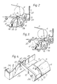
- Figure 1 is a part cut-away plan view of a retractable cleaner blade apparatus in accordance with the invention, showing part of the xerographic process cassette in which it is contained,
- Figure 2 is a sectional view of the apparatus in Figure 1 with the cleaner blade in the operative, cleaning position,
- Figures 3 is a sectional view of the apparatus in Figure 1 with the cleaner blade in the retracted, sealing position,
- Figure 4 is a perspective view showing a portion of the blade assembly and linear cam of the apparatus as viewed from right to left in Figure 1,
- Figure 5 is a front elevation showing the profile of the linear cam.
- Referring to Figures 1 and 2, there is shown a portion of a xerographic casette housing 1 containing a toner cleaner blade assembly 2 in accordance with the present invention. The xerographic cassette is suitably of the kind disclosed in our copending UK patent application 86 09160 (our ref: R/86003) and comprises a loosely held
endless photoreceptor belt 3 supported on guide rollers 4 (only one of which is shown in Figure 2). The cassette is intended for insertion into a xerographic copier which has an aperture to accept the cassette, within which aperture there is located a drive and location shaft for the photoreceptor which is cantilevered from the rear of the machine. As described in the aforementioned copending patent application this shaft may have a tapered end to aid engagement of the photoreceptor guide rollers over the shaft, and could be of the expanding mandrel type. When the cassette is inserted into the machine, the photoreceptor is located by the drive and location shaft, thus minimising location errors between the photoreceptor and the imaging unit of the machine. Any or all of the guide rollers may be movable such as to space them further apart, operable after insertion of the cassette to locate and tension the photoreceptor belt. No further details need be given about the cassette for the purposes of understanding the present invention except to note that, as well as containing the photoreceptor and cleaner blade assembly, the cassette may also contain one or more other xerographic process assemblies, such as charging, erasing, development, or transfer assemblies, as is known. - The cleaner blade assembly itself will now be described with additional reference to Figure 4. A conventional
elastomeric cleaner blade 5 made, for example, of polyurethane or the like is mounted in ablade holder 6 in such manner that the blade extends from the holder typically by about 5 to 8 mm. Theholder 6 which suitably is extruded aluminium has a U-shaped slot 7 providing a tight push-fit for theblade 5. Theholder 6 may be curved or angled to provide the appropriate mounting angle for the cleaner blade as discussed in more detail below. The upper side of theholder 6 is tapered at its end 8 towards the mouth of slot 7, whereas the under side of theholder 6 has a downwardly extending lip 9, the purpose of which will be described below. - The blade and holder assembly is supported between two
arms 10 extending generally at right angles to the longitudinal direction of theblade 5 andholder 6. Eacharm 10 has at its lower end an inwardly extendingsupport member 11 with a narrowerdimensioned extension 12 which is push-fitted into a complementary aperture at the base edge of theholder 6. At the opposite end, each of thearms 10 has a hook-like head portion 10a having on its underside aslot 14 for cooperating with alinear cam 15 to be decribed below. - The blade assembly is mounted generally above a
chamber 16 for collecting waste toner. Thechamber 16 is in the form of a U-shaped well or sump in the bottom of the cassette housing and contains anauger arrangement 17a for recirculating the toner via a further auger arrangement 17b extending transversely thereto back to a toner supply reservoir (not shown) from where it can be reused in the development process. Alternatively, the augers may be dispensed with altogether, in which case thechamber 16 simply acts as a storage chamber for the waste toner. As seen in Figure 2, the side wall of thechamber 16 is lower on the left-hand side than on the right-hand side. Extending upwardly from the inside left-hand wall of the chamber is aflexible sealing strip 18, made for example from Mylar (Trade Mark) and fastened to the chamber wall. At the top of the right-hand wall of the chamber there is provided afoam sealing block 19. The purpose of thesealing strip 18 and thesealing block 19 will be explained in more detail below. - The blade assembly is mounted in the cassette and is arranged generally above the open top of the U-shaped toner collecting chamber. A
tab 21a on the outer side of eacharm 10 is accommodated inrespective slots 41 present within the internal wall construction of the cassette as shown schematically in Figure 2. - The blade assembly is biased towards the
photoreceptor 3 by a pair of torsion springs 20 located one at each end of the assembly, see Figure 1, the springs bearing againstposts 21 which are provided integrally with thearms 10. In the design shown in Figure 1 the left-hand arm 10 has the spring-buttingpost 21 on the outside whereas the right-hand arm 10 has thepost 21 on the inside. Of course other arrangements are possible and the springs may equally be provided so that theposts 21 are both on the outside or both on the inside of the arms. As shown in Figure 2 the spring biasing for the blade assembly may additionally (or alternatively) comprise acompression spring 40 bearing against the lower edge portion of thearm 10. Also, to assist in holding the blade assembly in place an L-shapedretaining clip 22 is slideably fixed in achannel 23 in the cassette housing. Theclip 22 bears downwardly against the upper end ofarm 10 allowing lateral movement of thearm 10. - Adjacent the
toner collecting chamber 16 in the cassette is achannel 23 in which is slideably mounted the aforementionedlinear cam 15. The three dimensional profile of thecam 15 can be seen by studying Figures 1, 4, and 5 in which Figure 4 is a perspective view, and Figures 1 and 5 are top and side elevations respectively. The operation of the cam will be described in more detail below. Thecam 15, which suitably is made of a moulded plastics material, for example acetal, has aflat base 24 and an upstanding flange-like member 25 extending along the full length, generally centrally of the base. Themember 25 has a similar profiled portion at each of its extremeties. In the plane of thecam base 24 the profiled portion is generally S-shaped. In the plane of themember 25 the profile has a low levelflat portion 32 to the left and then, moving left to right, an upwardlyinclined portion 33, followed by aplateau portion 34. Thearm 10 of the blade assembly is arranged so that theslot 14 therein cooperates with theupstanding flange 25, the upper end of thearm 10 thus effectively being hooked over thecam 15. Theclip 22 bearing on the blade assembly acts to keep thearms 10 in intimate contact with the flange likemember 25 so that they act as a pair of cam followers, the design of the cam being such that each of the arms is located at an equivalent position along the two S-shaped cam profiles. The biasing of the blade assembly 1 against thecam 15 also helps to hold thecam 15 in place vertically within the cassette. - A
tension spring 26 is connected at one end to aprojection 27 on thecam 15 and at the other end to amember 28 on the cassette housing 1, thus biasing the cam into the position shown in Figure 1. This is the retracted or sealing position of the blade assembly, that is to say when the cassette is outside the xerographic machine, see also Figure 3. In this condition theblade 5 andholder 6 are held firmly over thechamber 16 with theblade 5 butting against thefoam sealing block 19 and theflexible sealing strip 18 bearing against the underside of theblade holder 6. In this manner thechamber 16 is effectively sealed by the blade assembly preventing toner from escaping when the cassette is outside the xerographic machine. - When the cassette is inserted into the xerographic machine the flat
transverse end 29 ofcam 15 engages a fixedactuating rod 30 projecting from the main frame of the machine. The rod enters the cassette through anaperture 31 therein. As the cassette is pushed home to its working position so thecam 15 is pushed by therod 30 and the cam is displaced longitudinally. As the cam is displaced, thearms 10 of the blade assembly 1, acting as cam followers, are caused to move from the lowermost position of thecam profile 32 and ride up theinclined profile 33 on to thehigher plateau portion 34. In this movement thearms 10 are not only shifted vertically but also longitudinally so that the whole blade assembly is raised and displaced in the direction away from the cam. When the right-hand arm 10 (see Figure 1) has ascended theplateau portion 34 it abuts theend wall 29 of thecam 15, which acts as a stop preventing any further linear movement of thecam 15. At this point the blade assembly is in the cleaning position shown in Figure 2 with the blade engaging thephotoreceptor belt 3 below roller 4 in order to clean the residual toner therefrom. Suitably the approach angle of the blade may be arranged at a nominal 25° to the tangent at the contact point but in operation the blade will be deflected to reduce this approach angle to between 10 to 14°, for example. The loading of the blade may be chosen to be approximately 30 gcm⁻¹, for example. - As can be seen in Figure 2, the depending lip 9 of the
blade holder 6 bears against theflexible sealing strip 18 from the internal side of the chamber, deforming it to maximise the opening tochamber 16. At the opposite side of the chamber the sealingblock 19 is arranged to ride lightly against thephotoreceptor 3 thus forming a completely sealed entrance to thechamber 16 whereby all the toner scraped from thephotoreceptor 3 by theblade 5 falls under gravity directly into thechamber 16 without being able to escape into other parts of the cassette which would cause contamination. - When the cassette is removed from the xerographic machine the biasing
spring 26 will cause the cam to return to the position shown in Figure 1 in which the blade assembly is moved to the chamber sealing position shown in Figure 3 and already described above. As theblade assembly arms 10 are moved away from thephotoreceptor 3 towards thecam 15 thetabs 21a on thearms 10 eventually bear against a downwardly slopingportion 35 of theslot 41 in the cassette housing. Continuing lateral movement of the cam causes thetabs 21a to follow the inclined profile of theslots 41 downwardly which assists in urging the blade assembly into a more positive sealing relationship with theflexible sealing member 18 and the sealingblock 19. - As mentioned previously, it is a feature of the cassette disclosed in our copending British patent application number 86 09160 that the tension in the photoreceptor belt is reduced when the cassette is outside the xerographic machine by moving one of the guide rollers. In Figure 3 the roller 4 is thus shown displaced to the left away from the sealing
block 19 so that thephotoreceptor 3 is retained only loosely in readiness for the cassette to be withdrawn from the machine. - In the light of the embodiment described above it will be evident to a person skilled in the art that various modifications may be made within the scope of the present invention as claimed. For example, the projecting
rod 30 from the xerographic machine may initially be retracted in order not to engage the cam until after the cassette has been fully inserted into the working position. In this case an actuating lever or other device may be provided which causes the rod to project into abutment with the cam and may also be responsible for initiating other responses within the cassette, particularly movement of the photoreceptor belt guide rollers and the consequential tensioning of the photoreceptor belt, in readiness for operation. Furthermore, although a specific form of linear cam has been described for actuating the blade assembly it will be evident that other cam designs may equally be employed, particularly for example, a rotary cam arrangement.
Claims (13)
- Apparatus for separating residual toner material from the surface of a re-usable image retaining member of a reproducing machine, comprising
blade means (5, 6) arranged for movement between two positions wherein at the first position (Fig. 2) the blade means operatively engages the image retaining member (3) to remove said residual toner material therefrom and at the second position (Fig. 3) the blade means is spaced apart from the imaging retaining member, and
a generally enclosed chamber (16) with an opening for collecting the residual toner material as it is removed by said blade means,
characterized in that
in said second position the blade means completely covers the opening and closes the chamber in such a manner as to form a sealed enclosure to prevent the toner material contained therein from escaping. - A process unit adapted to be removably mounted in a main assembly of a reproducing machine, the process unit including an image retaining member and apparatus as claimed in claim 1 for separating residual toner material from the surface of said image retaining member, wherein the image retaining member is loosely retained in the process unit when the process unit is removed from the main assembly and is adapted to be supported in an operative position by support means forming part of the main assembly when the process unit is inserted into the main assembly.
- The process unit of claim 2, wherein said image retaining member is a belt photoreceptor comprising an end less flexible belt having a photosensitive surface.
- The process unit as claimed in claim 2 or claim 3, wherein the blade means is actuated by a linear cam (15).
- The process unit as claimed in claim 4, wherein the linear cam is slideably mounted in a channel (23) immediately adjacent the toner collecting chamber.
- The process unit is claimed in claim 5, wherein the linear cam is actuated by a projecting member(30) on the main assembly.
- The process unit as claimed in claim 5 or claim 6, wherein the linear cam comprises a flat base (24) having an upstanding flange-like member (25) providing the cam profile.
- The process unit as claimed in claim 7, wherein the profile of the linear cam is arranged to cause pivotal and lateral movement of the blade means.
- The process unit as claimed in any of claims 5 to 8, further comprising spring means (26) which bias the cam into the position in which the blade means seals the chamber.
- The process unit as claimed in any of claims 5 to 9, wherein the blade means is supported at each end by an arm (10) having a hook-like portion (10a) with a slot (14) which cooperates with the linear cam to act as a cam follower.
- The process unit as claimed in claim 10, wherein a tab (21a) is provided on the side of each arm, which tabs are arranged to cooperate with slots (41) in the process unit, the slots being provided with a sloping end wall (35) whereby as the blade means is moved to the second, sealing position the tabs engage the sloping end wall and are moved downwardly along said end wall thereby urging the blade means into positive sealing relationship with the chamber.
- The process unit as claimed in any one of claims 2 to 11, further comprising another spring means (20, 40) which bias the blade means into engagement with the image retaining member.
- The process unit as claimed in any one of claims 2 to 12, wherein there is provided, around the opening in the chamber, sealing members (18, 19) arranged to abut the blade means when the blade means is in said second, sealing position.
Applications Claiming Priority (2)
| Application Number | Priority Date | Filing Date | Title |
|---|---|---|---|
| GB8618186 | 1986-07-25 | ||
| GB868618186A GB8618186D0 (en) | 1986-07-25 | 1986-07-25 | Toner cleaning apparatus |
Publications (2)
| Publication Number | Publication Date |
|---|---|
| EP0254571A1 EP0254571A1 (en) | 1988-01-27 |
| EP0254571B1 true EP0254571B1 (en) | 1992-04-01 |
Family
ID=10601678
Family Applications (1)
| Application Number | Title | Priority Date | Filing Date |
|---|---|---|---|
| EP87306523A Expired EP0254571B1 (en) | 1986-07-25 | 1987-07-23 | Toner cleaning apparatus |
Country Status (5)
| Country | Link |
|---|---|
| US (1) | US4796057A (en) |
| EP (1) | EP0254571B1 (en) |
| JP (1) | JP2601826B2 (en) |
| DE (1) | DE3777904D1 (en) |
| GB (1) | GB8618186D0 (en) |
Families Citing this family (7)
| Publication number | Priority date | Publication date | Assignee | Title |
|---|---|---|---|---|
| US4862209A (en) * | 1987-03-05 | 1989-08-29 | Ricoh Company, Ltd. | Image forming apparatus having a removable image forming process kit |
| JPH0713007Y2 (en) * | 1988-08-11 | 1995-03-29 | 三田工業株式会社 | Image forming device cleaning device |
| DE69021326T2 (en) * | 1989-11-07 | 1996-01-11 | Konishiroku Photo Ind | Imaging unit with a belt. |
| GB2241089B (en) * | 1990-02-20 | 1993-12-08 | Xerox Corp | Electrostatographic machine |
| US5386282A (en) * | 1993-11-15 | 1995-01-31 | Xerox Corporation | Blade controller assembly with modified cam |
| US6088564A (en) * | 1999-08-13 | 2000-07-11 | Xerox Corporation | Translating tribocharging blade |
| JP4544180B2 (en) * | 2006-03-01 | 2010-09-15 | ブラザー工業株式会社 | Image forming apparatus |
Family Cites Families (17)
| Publication number | Priority date | Publication date | Assignee | Title |
|---|---|---|---|---|
| US3660863A (en) * | 1969-07-03 | 1972-05-09 | Xerox Corp | Cleaning apparatus |
| US3838472A (en) * | 1971-09-27 | 1974-10-01 | Xerox Corp | Toner cleaning apparatus |
| US3985436A (en) * | 1974-06-25 | 1976-10-12 | Minolta Camera Kabushiki Kaisha | Electrophotographic copying apparatus |
| DE2436301A1 (en) * | 1974-07-27 | 1976-02-12 | Agfa Gevaert Ag | ELECTROSTATIC COPY DEVICE |
| US4218131A (en) * | 1975-01-17 | 1980-08-19 | Canon Kabushiki Kaisha | Cleaning device |
| US4158498A (en) * | 1976-06-22 | 1979-06-19 | Rank Xerox Limited | Blade cleaning system for a reproducing apparatus |
| JPS5882285A (en) * | 1981-11-10 | 1983-05-17 | Canon Inc | Image forming device |
| DE3303119A1 (en) * | 1982-03-02 | 1983-09-08 | Minolta Camera K.K., Osaka | WIPER CLEANER |
| US4530594A (en) * | 1982-05-21 | 1985-07-23 | Canon Kabushiki Kaisha | Cleaning device |
| JPS5953859A (en) * | 1982-09-22 | 1984-03-28 | Canon Inc | process kit |
| JPS59198476A (en) * | 1983-04-26 | 1984-11-10 | Canon Inc | developing device |
| JPS6011868A (en) * | 1983-07-01 | 1985-01-22 | Fuji Xerox Co Ltd | Fur brush cleaning device of electrophotography copying machine |
| US4571071A (en) * | 1984-04-13 | 1986-02-18 | Eastman Kodak Company | Cleaning apparatus and method for a polychromatic electrophotographic copier |
| US4564283A (en) * | 1984-06-22 | 1986-01-14 | Xerox Corporation | Blade cleaner apparatus for removing toner from a charge-retentive surface |
| US4561766A (en) * | 1984-06-22 | 1985-12-31 | Xerox Corporation | Blade cleaner apparatus for removing toner from a charge-retentive surface |
| JPH0711735B2 (en) * | 1985-11-25 | 1995-02-08 | 三田工業株式会社 | Electrostatic copying machine |
| JPH0711736B2 (en) * | 1985-11-27 | 1995-02-08 | 三田工業株式会社 | Electrostatic copying machine |
-
1986
- 1986-07-25 GB GB868618186A patent/GB8618186D0/en active Pending
-
1987
- 1987-07-10 JP JP62172726A patent/JP2601826B2/en not_active Expired - Lifetime
- 1987-07-23 DE DE8787306523T patent/DE3777904D1/en not_active Expired - Fee Related
- 1987-07-23 EP EP87306523A patent/EP0254571B1/en not_active Expired
- 1987-07-23 US US07/076,809 patent/US4796057A/en not_active Expired - Lifetime
Also Published As
| Publication number | Publication date |
|---|---|
| JP2601826B2 (en) | 1997-04-16 |
| JPS6334576A (en) | 1988-02-15 |
| DE3777904D1 (en) | 1992-05-07 |
| EP0254571A1 (en) | 1988-01-27 |
| GB8618186D0 (en) | 1986-09-03 |
| US4796057A (en) | 1989-01-03 |
Similar Documents
| Publication | Publication Date | Title |
|---|---|---|
| US4888620A (en) | Process cartridge and image forming apparatus using the same | |
| US5095335A (en) | Copier with retractable charging unit to prevent damage to drum when removing process cartridge | |
| EP0251823B1 (en) | Waste toner collecting system | |
| US4766455A (en) | Process unit for an imaging apparatus | |
| US5438391A (en) | Clamshell-type image forming apparatus | |
| US4835568A (en) | Removable process unit with charging device located relative to main assembly | |
| EP0940732A2 (en) | Toner container | |
| US4806967A (en) | Electrostatographic reproducing machine and process unit therefor | |
| US4796057A (en) | Toner cleaning apparatus | |
| US5444522A (en) | Replaceable cleaner subsystem that prevents particle spillage | |
| US4841333A (en) | Process unit for an imaging apparatus | |
| EP0227488A2 (en) | Full waste toner container detector | |
| JPS6114679A (en) | Cleaner for removing residual toner and copying equipment using the same | |
| EP0230791B1 (en) | Full waste toner container detector | |
| CA2203452C (en) | Image forming machine having a verifiably openable sump shutter assembly | |
| US4827308A (en) | Process unit for an imaging apparatus | |
| US4831407A (en) | Process unit for an imaging apparatus | |
| US4786938A (en) | Process unit for an imaging apparatus | |
| US5111246A (en) | Electrostatographic machine | |
| JP3457775B2 (en) | Electrophotographic equipment | |
| US5034779A (en) | Fibre traps in electrostatographic machines | |
| JP2002333813A (en) | Process cartridge, electrophotographic image forming apparatus, and electrophotographic image forming system | |
| JP3635621B2 (en) | Image forming apparatus | |
| US5386282A (en) | Blade controller assembly with modified cam | |
| JPH0334767Y2 (en) |
Legal Events
| Date | Code | Title | Description |
|---|---|---|---|
| PUAI | Public reference made under article 153(3) epc to a published international application that has entered the european phase |
Free format text: ORIGINAL CODE: 0009012 |
|
| AK | Designated contracting states |
Kind code of ref document: A1 Designated state(s): DE FR GB IT |
|
| 17P | Request for examination filed |
Effective date: 19880630 |
|
| 17Q | First examination report despatched |
Effective date: 19901205 |
|
| GRAA | (expected) grant |
Free format text: ORIGINAL CODE: 0009210 |
|
| AK | Designated contracting states |
Kind code of ref document: B1 Designated state(s): DE FR GB IT |
|
| REF | Corresponds to: |
Ref document number: 3777904 Country of ref document: DE Date of ref document: 19920507 |
|
| ET | Fr: translation filed | ||
| ITF | It: translation for a ep patent filed | ||
| PLBE | No opposition filed within time limit |
Free format text: ORIGINAL CODE: 0009261 |
|
| STAA | Information on the status of an ep patent application or granted ep patent |
Free format text: STATUS: NO OPPOSITION FILED WITHIN TIME LIMIT |
|
| 26N | No opposition filed | ||
| PGFP | Annual fee paid to national office [announced via postgrant information from national office to epo] |
Ref country code: FR Payment date: 20010712 Year of fee payment: 15 |
|
| PGFP | Annual fee paid to national office [announced via postgrant information from national office to epo] |
Ref country code: DE Payment date: 20010716 Year of fee payment: 15 |
|
| PGFP | Annual fee paid to national office [announced via postgrant information from national office to epo] |
Ref country code: GB Payment date: 20010718 Year of fee payment: 15 |
|
| REG | Reference to a national code |
Ref country code: GB Ref legal event code: IF02 |
|
| PG25 | Lapsed in a contracting state [announced via postgrant information from national office to epo] |
Ref country code: GB Free format text: LAPSE BECAUSE OF NON-PAYMENT OF DUE FEES Effective date: 20020723 |
|
| PG25 | Lapsed in a contracting state [announced via postgrant information from national office to epo] |
Ref country code: DE Free format text: LAPSE BECAUSE OF NON-PAYMENT OF DUE FEES Effective date: 20030201 |
|
| GBPC | Gb: european patent ceased through non-payment of renewal fee |
Effective date: 20020723 |
|
| PG25 | Lapsed in a contracting state [announced via postgrant information from national office to epo] |
Ref country code: FR Free format text: LAPSE BECAUSE OF NON-PAYMENT OF DUE FEES Effective date: 20030331 |
|
| REG | Reference to a national code |
Ref country code: FR Ref legal event code: ST |
|
| PG25 | Lapsed in a contracting state [announced via postgrant information from national office to epo] |
Ref country code: IT Free format text: LAPSE BECAUSE OF NON-PAYMENT OF DUE FEES;WARNING: LAPSES OF ITALIAN PATENTS WITH EFFECTIVE DATE BEFORE 2007 MAY HAVE OCCURRED AT ANY TIME BEFORE 2007. THE CORRECT EFFECTIVE DATE MAY BE DIFFERENT FROM THE ONE RECORDED. Effective date: 20050723 |