EP0253871B1 - Direct access test unit for central office - Google Patents
Direct access test unit for central office Download PDFInfo
- Publication number
- EP0253871B1 EP0253871B1 EP87900940A EP87900940A EP0253871B1 EP 0253871 B1 EP0253871 B1 EP 0253871B1 EP 87900940 A EP87900940 A EP 87900940A EP 87900940 A EP87900940 A EP 87900940A EP 0253871 B1 EP0253871 B1 EP 0253871B1
- Authority
- EP
- European Patent Office
- Prior art keywords
- test
- test unit
- access port
- line
- unit according
- Prior art date
- Legal status (The legal status is an assumption and is not a legal conclusion. Google has not performed a legal analysis and makes no representation as to the accuracy of the status listed.)
- Expired
Links
- 238000012360 testing method Methods 0.000 title claims abstract description 180
- 238000001514 detection method Methods 0.000 claims description 7
- 230000004044 response Effects 0.000 claims description 7
- 230000005236 sound signal Effects 0.000 claims description 6
- 230000000977 initiatory effect Effects 0.000 claims description 3
- 230000002194 synthesizing effect Effects 0.000 claims description 2
- 238000013024 troubleshooting Methods 0.000 abstract description 2
- 230000006870 function Effects 0.000 description 30
- 230000008439 repair process Effects 0.000 description 6
- 238000004804 winding Methods 0.000 description 6
- 238000004891 communication Methods 0.000 description 4
- 230000003287 optical effect Effects 0.000 description 4
- 230000009471 action Effects 0.000 description 3
- 230000008859 change Effects 0.000 description 3
- 238000000034 method Methods 0.000 description 3
- 229930191976 simplextone Natural products 0.000 description 3
- 230000000694 effects Effects 0.000 description 2
- 238000012986 modification Methods 0.000 description 2
- 230000004048 modification Effects 0.000 description 2
- 239000003990 capacitor Substances 0.000 description 1
- 238000010276 construction Methods 0.000 description 1
- 238000013461 design Methods 0.000 description 1
- 238000010586 diagram Methods 0.000 description 1
- 238000009434 installation Methods 0.000 description 1
- 230000007257 malfunction Effects 0.000 description 1
- 238000004519 manufacturing process Methods 0.000 description 1
- 238000012544 monitoring process Methods 0.000 description 1
- 230000008569 process Effects 0.000 description 1
- 230000011664 signaling Effects 0.000 description 1
Images
Classifications
-
- H—ELECTRICITY
- H04—ELECTRIC COMMUNICATION TECHNIQUE
- H04M—TELEPHONIC COMMUNICATION
- H04M3/00—Automatic or semi-automatic exchanges
- H04M3/22—Arrangements for supervision, monitoring or testing
- H04M3/26—Arrangements for supervision, monitoring or testing with means for applying test signals or for measuring
- H04M3/28—Automatic routine testing ; Fault testing; Installation testing; Test methods, test equipment or test arrangements therefor
- H04M3/30—Automatic routine testing ; Fault testing; Installation testing; Test methods, test equipment or test arrangements therefor for subscriber's lines, for the local loop
-
- H—ELECTRICITY
- H04—ELECTRIC COMMUNICATION TECHNIQUE
- H04M—TELEPHONIC COMMUNICATION
- H04M3/00—Automatic or semi-automatic exchanges
- H04M3/42—Systems providing special services or facilities to subscribers
- H04M3/487—Arrangements for providing information services, e.g. recorded voice services or time announcements
Definitions
- the present invention relates to a direct access test unit to be connected in a central office for testing subscriber lines, which has an input access port and an output access port, a generator for generating dialing signals and a processor for controlling the generator, whereby the output access port has tip, ring, sleeve and ground terminals for connection to a test trunk circuit in the central office, and more particularly to a direct access test unit located within a central office and which allows a field repair person to perform specific pre-test functions on any selected subscriber line from a remote location without assistance of personnel within the central office.
- US-Patent No. 4 438 298 (Harvey) is directed to the testing of subscriber loops using a loop testing systems; the testing performed in the Harvey system is controlled from a central repair service bureau via operator consoles 230, 231, which interface through front-end computers 220, 221 to a data communication network 140 via digital communication lines.
- the loop testing systems (LTS) 160, 161 in wire centers 150, 151 communicate with the data communication network 140 via digital data links 930, 931 on the basis of a serial-orientated protocol (column 27, line 21 to 23).
- the LTS 160 is connected to a test trunk circuit in the wire center 150 via ports 2801 to 2816 and a sleeve lead control 2950 with Tip, Ring and Sleeve lines 9401 to 9432 in response to the digital commands received from the operator consoles 230, 231.
- the LTS comprises two controllers 2000 and 2200 which receive digital commands and control the functions of the LTS. They also control a trunk dealer 2650 generating dialing signals.
- the Harvey system is designed for testing subscriber lines by personnel in the central repair bureau. It is not possible for field repair personnel to test a subscriber line without assistance of personnel in the central repair service bureau.
- a further object of the present invention resides in the provision of a direct access test unit which allows the field technician to selectively perform various tests on any subscriber line through a central office from a remote location without the assistance of personnel at the central office.
- Still a further object of the present invention is to provide a direct access test unit whose operations may be determined and modified from a remote location by authorized personnal performing selected programming functions.
- an direct access test unit which is characterized in that the input access port has tip and ring terminals for connection to a line circuit in a central office, and wherein there is provided decoder means connected to the input access port for detecting and decoting dialing signals indicating a designated subscriber line and received from a remote location via said line circuit; said processor including control means responsive to decoded dialing signals received from the decoder means for connecting the generator to the output access port and for controlling the generator to generate dialing signals indicating the designated subscriber line.
- the direct access test unit is installed within the equipment frame inside the central office, and it has an access port connected to a ground start line circuit and an output port connected to a no-test trunk circuit.
- the device is compatible with all types of central offices, such as an electronic switching system or a cross bar central office.
- dial tone is provided to indicate that the device is waiting for a security code entry, and upon receipt of the security code entry, dial tone is again supplied to indicate that the device is waiting for a subscriber number entry.
- the field technician may then access any subscriber line through the central office by generating the appropriate subscriber number, and the device will access that subscriber line via the test trunk connected to its output port.
- One of the features of the present invention resides in the provision of voice messages to guide the field technician through various test operations and to explain a resulting error condition when detected.
- the device provides an appropriate voice message to indicate to the technician the next operation to be performed or a selection of tests available and the codes required for selection of these tests.
- the device is designed so as to not interfere with a legitimately busy line.
- all test functions except for application of the low level simplex tone, are disabled.
- the device allows the field technician to monitor the busy subscriber line; although, the voice data on the line is scrambled so as to not be intelligible. This permits the field technician to determine what signals are on the line and also to determine whether the line is legitimately busy.
- a further feature of the present invention resides in the fact that the device allows the field technician to access a new subscriber line without going on hook, thereby significantly reducing the access time to complete a test operation involving a number of subscriber lines.
- the device will normally disconnect the subscriber line immediately after the field technician goes on hook; however, it also has the capability of continuing any test function for a period of time after the subscriber has gone on hook, if so directed.
- Access to the device requires the generation of a particular security code by the field technician, and the line is automatically released after a predetermined number of unsuccessful attempts to generate the correct security code.
- the device is able to translate seven digits to five digits and add up to ten different steering digits for central offices requiring only five digits access.
- the direct access test unit which is to be installed within the central office, has an input access port section and an outgoing trunk section.
- the input access port section has an input port providing tip T and ring R terminals for connection to a standard ground start line circuit.
- the tip T and ring R terminals are connected via a rectifier bridge BR1, which forms part of the ring detect circuit 10, to a standard line transformer T2 of the type typically found in line circuits.
- a line seize circuit 12 is connected via the rectifier bridge BR1 across the primary windings of the line transformer T2, and a relay K4 is also connected to the primary windings of the line transformer T2 for performing loop current detection.
- the first of these circuits is a DTMF decoder 14 which detects multifrequency dial tones received via the line circuit connected to the tip T and ring R terminals and decodes these tones to the corresponding subscriber line numbers.
- the second circuit comprises a 440 Hz generator 18 which supplies secondary dial tone via the amplifier 16 to indicate to the user that the device is waiting for either a subscriber number entry or a security code entry.
- the third circuit is a speech synthesizer circuit 20 which provides various voice messages through the amplifier 16 to guide the user through each test operation and to explain detected error conditions.
- the fourth circuit is a subscriber line audio monitor 22 which applies audio in scrambled form from a subscriber line under test, when that line is indicated as busy, through the line transformer T2 so that the field technician may monitor the audio.
- These four circuits 14, 18, 20 and 22 operate under control of a microcomputer 25.
- the outgoing trunk section of the direct access test unit is provided with an output port including tip T, ring R, sleeve S and ground G terminals to be connected within the central office to a standard no-test trunk circuit, such as a Western Electric Company type 1A 186-01 or equivalent.
- the tip T and ring R terminals are connected through standard relays L1 and L2 and a rectifier bridge BR2 to the primary windings of line transformer T1.
- the rectifier bridge BR2 forms part of a trunk seize circuit 30, which is controlled by the microcomputer 25, and there is also connected across the bridge rectifier BR2 a battery reverse detection circuit 32.
- the secondary windings of the line transformer T1 are connected to the subscriber line audio monitor 22 and also to a multifrequency generator 36 from which multifrequency signalling is applied through the transformer T1 to the tip and ring leads to the no-test trunk under control of the microcomputer 25.
- a busy detect circuit 34 is also corrected across the tip T and ring R terminals of the output port to detect a busy condition of the subscriber line under test.
- a test function circuit 35 includes various relays which operate to perform the desired tests of the subscriber line accessed through the no-trunk circuit and a sleeve control circuit 37 controls communication with the no-test trunk via the sleeve S after the direct access test unit has cut through to the no-test trunk.
- a 577 HZ generator 38 performs the tests involving the application of high level and low level test tones across the tip and ring leads to the subscriber line under test.
- the speech synthesizer circuit 20, the subscriber line audio monitor 22, the multifrequency generator 36 and the 577 Hz generator 38 are controlled by a device select decoder 24 in response to a 3-bit code supplied from the microcomputer 25 In this way, these circuits can be selected for operation one at a time under control of the microcomputer 25.
- the ground start line circuit connected to the tip T and ring R terminals of the input access port of the direct access test unit will apply ringing to the rectifier bridge BR1 in the ring detector circuit 10. Ringing voltage of more than 55 volts RMS will cause the Zener diode CR1 to conduct, which completes the circuit through the resistance R3 and the optical isolator U1 across the output of the bridge BR1.
- the optical isolator U1 When the optical isolator U1 is turned on, the capacitor C1 charges, and the signal is supplied through the inverter U2 and line L1 to the microcomputer 25 to indicate that ringing has been detected.
- the microcomputer 25 responds by applying a signal on line L2, causing the optical isolator U2 in the line seize circuit 12 to turn on, which causes the transistor Q1 to conduct, closing the loop across the incoming tip and ring lines. This causes ring trip in the ground start line circuit.
- the relay K4 connected to the primary windings of the bridging transformer T2, applying a signal on line L0 to the microcomputer 25 to indicate the detection of loop current.
- the microcomputer 25 supplies a 440 Hz square wave to the input of the generator 18, which is composed of a multiple feedback bandpass filter having a center frequency at 440 Hz and an integrator, for purposes of supplying secondary dial tone through the amplifier 16 and bridging transformer T2 to the line.
- the field technician Upon receiving this secondary dial tone, it is necessary for the field technician to dial a user security code to gain access to use of the test unit, and this user security code, which is stored in the microcomputer 25 should be known to the field technician, if he is authorized to utilize this test unit. If the field technician takes no action at all, the microcomputer will automatically release the line after a certain predetermined time has expired.
- the dialing signals will be received and detected by the DTMF decoder 14, and a four bit digit will be supplied on lines L3-L6 to the microcomputer 25 to identify each digit of the dialed code.
- the received digits are then compared with the user security code stored within the microcomputer 25 to determine whether the user should be permitted access to the test unit.
- Detection of the first dialed digit by the decoder 14 causes the microcomputer 25 to instantly remove the secondary dial tone from the line, as is conventionally done in standard line circuits, and if the digits received by the microcomputer 25 correspond to the authorized user access code, secondary dial tone will be supplied once again from the generator 18 to the line to inform the field technician that he has been given access to the test unit. If the received digits do not correspond to the authorized user access code, the secondary dial tone will not be applied to the line for the second time and the field representative will then know that he has either made an error in dialing the access code or has the wrong access code.
- the microcomputer 25 will permit the user to try again a predetermined number of times to obtain access to the test unit by supplying the proper user access code; however, if this is not achieved within a predetermined number of tries, the microcomputer 25 would automatically release the line. The field representative will then know that he has either made an error in dialing the access code or has the wrong access code. Further, when dialing the user access code, if the first digit of the code is not entred within a certain period of time of receipt of a dial tone, or if too much time elapses between digits, the unit will automatically disconnect.
- the microcomputer 25 will select the speech synthesizer circuit via the device select decoder 24 and apply a strobe signal on line L7 thereto along with address signals selecting a chip from which the voice message "dial seven digit subscriber line number" is read as an audio signal through the amplifier 16.
- the voice message which occurs seven seconds after the start of the second dial tone, informs the user that a seven digit subscriber line number should be dialed at that time.
- test unit Obviously, if the field technician is familiar with the use of the test unit, he will not need to wait for the voice message, but can immediately begin dialing the seven digit subscriber line number upon receipt of the second dial tone, in which case the microcomputer 25 will not call upon the speech synthesizer circuit 20. If a digit is not dialed within one minute of receipt of the secondary dial tone, the unit simply disconnects.
- the seven digit subscriber line number dialed by the field technician will be detected by the decoder 14 and the digits will be supplied to the microcomputer 25.
- the microcomputer 25 is programmed to translate the seven digits to four or five digits and to add up to ten different steering digits for those central offices requiring only four or five digits access.
- the microcomputer 25 seizes the trunk circuit by outputting a logic high on line L8 to the inverter U3, which inverts this signal and turns on the optical isolator U3 which renders the transistor Q2 conductive, closing the loop across tip and ring on the outgoing trunk, and then selects the multifrequency generator 36 via the device select decoder 24 and supplies thereto a control signal for selecting the frequency pairs which designate the various digits required to identify the subscriber line circuit to be accessed.
- These multifrequency signals are supplied from the generator 36 through the line transformer T1 to the tip and ring lines of the no-test trunk. Reverse battery supervision is detected by the circuit 32, in which the opto-isolator 34 detects battery reversal and signals this condition to the microcomputer 25 via line L14.
- the busy detector circuit 34 will determine whether the line circuit is busy by detecting the level of the loop current and the level of the voltage on the ring lead. If the subscriber line is busy, the busy detector circuit 34 will signal this condition to the microcomputer 25 on line L9 and all testing of the subscriber line circuit will be inhibited except for application of the low level simplex tone. At this point, the microcomputer 25 does two things. First of all, it accesses the speech synthesizer 20 via the device select decoder 24 and applies the strobe signal on line L7 along with the address signals necessary to read out the voice message "busy line" to the user via the amplifier 16 and line transformer T2.
- the audio monitor test function is automatically invoked by the microcomputer 25, which selects the subscriber line audio monitor 22 via the device select decoder 24.
- the subscriber line audio monitor 22 receives the audio on the accessed subscriber line via the line transformer T1, scrambles it and applies the scrambled audio directly to the line transformer T2 so that the field technician can monitor this scrambled audio signal.
- the field technician may also dial a single digit to provide application of the low level simplex tone to the subscriber line, which is the only test not disabled under these conditions, but attempts to initiate other tests of the busy circuit will simply result in a repeat of the voice message "busy line".
- the unit will automatically return to the test mode and a voice message will be generated to indicate the options available as will be explained later.
- the microcomputer 25 will again access the speech synthesizer circuit 20 via the device select decoder 24 and apply the strobe signal on line L7 along with proper addresses to read out a voice message "OK".
- This voice message indicates to the field technician that access has been made to the designated subscriber line, which has been found to be idle. The field technician may then dial a single digit to select a particular test to be performed with respect to the subscriber circuit, and he will do so immediately if he is familiar with the test unit and its operation.
- the microcomputer 25 will again enable the speech synthesizer circuit 20 to read out a series of voice messages listing the different test functions that may be performed by dialing various digits.
- voice messages An example of such voice messages is indicated below: DIAL TWO FOR AUDIO MONITOR DIAL FOUR FOR HIGH LEVEL TONE DIAL FIVE FOR LOW LEVEL TONE DIAL SIX TO OPEN SUBSCRIBER LINE DIAL SEVEN TO SHORT SUBSCRIBER LINE DIAL STAR TO KEEP TEST AFTER DISCONNECT DIAL POUND FOR NEW SUBSCRIBER LINE
- the field technician may then select one of the test functions to be initiated and dial the appropriate digit.
- the microcomputer 25 will cause the speech synthesizer circuit 20 to issue a voice message identifying that test function, such as "audio monitor”, "high level tone”, “low level tone”, “open line” and "short line".
- a voice message identifying that test function, such as "audio monitor”, "high level tone”, “low level tone”, “open line” and "short line”.
- the voice message "dial number of minutes” will be read out, and the field technician is expected to dial a single digit to designate the number of minutes the test currently in progress is to remain in effect after disconnect.
- the test unit normally will disconnect immediately when the subscriber goes on hook, the unit has the capability of continuing a test function from one to ten minutes after going on hook, if so instructed.
- the field technician may then dial another digit to select a new test or utility function.
- the field technician may simply dial POUND for a new subscriber line, and the microcomputer 25 will place secondary dial tone from the generator 18 on the line indicating that the unit is prepared to receive the dialed digits relating to a new subscriber line.
- the various test functions are performed by selectively operating the relays K1, K3 and K3 in the test function circuit 35 from the microcomputer 25.
- the microcomputer 25 places a high on line L10 to the inverter I4 so as to operate the relay K1 which opens the tip and ring lines connected from the rectifier bridge BR2 to the tip T and ring R terminals of the output port.
- the microcomputer 25 places a high on line L11 to the inverter I5 so as to operate the relay K2. This places a short across the tip and ring lines to the trunk circuit so that a short test of the DC resistance can be made.
- the microcomputer 25 selects the 577 Hz generator 38 via the device select decoder 24. For a low level tone test, the microcomputer 25 maintains a low on the line L12 to the inverter I6 so as to maintain the relay K3 unenergized. The low level tone will then be applied from the generator 38 across tip and ring to perform the longitudinal simplex low level tone test which will not disturb traffic on a busy line. To perform the differential high level tone test, the microcomputer 25 places a high on line L12 while the generator 38 is selected so as to energize the relay K3 via the inverter I6. This places the high level tone across tip and ring to the trunk circuit.
- the test unit has two current level control, i.e., both high and low, on the sleeve to the no-test trunk. After the test unit cuts through to the test trunk, it communicates with the trunk via the sleeve current. For the low current state, the microcomputer 25 maintains a low on the line L13 so that current on the sleeve will pass both through resistor R4 and resistor R5. In the high current state, however, the microcomputer 25 will place a high on line L13 to the inverter I7, so that current passes only through the resistor R5, bypassing the resistor R4.
- the test unit may also be programmed for those subscriber line prefixes which will be used in the testing of line circuits. For this purpose, a predetermined number of three-digit prefixes can be stored in the memory of the microcomputer 25. If an attempt is made during subscriber line number entry to use a prefix that has not been programmed, the unit will respond with an error message.
- the microcomputer 25 is a conventional device including a microprocessor and non-volatile memory for storing of data and programs necessary to perform the functions described herein. In addition to controlling the overall operation of the direct access test unit, the microcomputer 25 performs certain housekeeping tasks, such as maintaining a count of the various accesses to the unit, storing of data relating to subscriber lines to be accessed, storing the required security codes and maintaining a listing of the identification of prefixes to be used for the different tests capable of being initiated by the test unit.
- the test unit In addition to accessing subscriber lines and initiating various designated tests with respect to these lines, it is also possible to access the test unit for purposes of changing the data stored therein relating to security access codes, the prefixes utilized to identify the test functions and to obtain access to the various counters for obtaining a reading of the data therein.
- the field technician simply dials the number of the ground start line circuit connected to the input port of the test unit in the same manner already described, but upon initial receipt of the secondary dial tone, instead of dialing a user security code, the field technician will dial a system security code.
- the microcomputer 25 will respond to a correctly dialed system security code by reading out from the speech synthesizer circuit 20 the message "OK".
- the field technician can then dial a single digit to select a particular programming function. If he does not do so within seven seconds after the "OK" message, the microcomputer 25 will automatically read out a series of voice messages identifying the different single digits which will initiate various programming functions.
- the microcomputer 25 will cause the speech synthesizing circuit 20 to read out a voice message identifying that programming function or indicating the next operation to be performed by the field technician to complete the selected programming function.
- the present invention provides a direct access test unit which allows the field technician to access any line circuit within the central office through a single designated line circuit connected to the input port of the test device while he is trying to trouble-shoot a problem. In this way, he bypasses all of the normal personnel previously required to perform such tests through the central office, thereby facilitating more complete automation of the central office.
- a considerable saving in the time required for the testing of line circuits also results from the fact that the field technician does not need to initiate a new connection to the central office each time a new subscriber line is to be tested.
Landscapes
- Engineering & Computer Science (AREA)
- Signal Processing (AREA)
- Monitoring And Testing Of Exchanges (AREA)
Abstract
Description
- The present invention relates to a direct access test unit to be connected in a central office for testing subscriber lines, which has an input access port and an output access port, a generator for generating dialing signals and a processor for controlling the generator, whereby the output access port has tip, ring, sleeve and ground terminals for connection to a test trunk circuit in the central office, and more particularly to a direct access test unit located within a central office and which allows a field repair person to perform specific pre-test functions on any selected subscriber line from a remote location without assistance of personnel within the central office.
- In order to provide the high degree of dependability and efficiency of service demanded by the public, it is necessary to maintain telephone equipment in properly working order at all times and to make it possible to detect and correct faults in such equipment quickly, so as to reduce disruption of service to a minimum. For this purpose, there have been developed various types of automatic central office test equipment which operates independently within the central office to periodically test all circuits to determine that they are operating properly, and when faults are detected, the location and identification of the fault is indicated so that repair may be made to maintain proper service. However, this equipment is confined to the central office, and is not accessible to service personnel from remote locations for selecting testing of subscriber lines.
- During the course of installation of subscriber equipment, as well as during the testing of subscriber lines to detect malfunctions, it is often necessary for service personnel located at the site of the subscriber equipment to effect certain tests of the subscriber lines associated with that equipment through the central office. For this purpose, there is equipment located at central offices which permits the linesman to conduct mechanical loop tests, dial-up for test tones and dial-up "quiet termination" tests, whereby resistance is placed across the line at the central office. However, all such tests are limited to the testing of the single subscriber line which the linesman is presently connected to at the central office. The testing of other lines at the cental office as desired by the linesman can be effected only by contacting personnel within the central office for assistance in connection with such tests, or by effecting connection to successive subscriber lines to perform individual tests on these lines, which is a tedious process.
- Thus, with present-day equipment, the operation to be performed by the linesman in testing subscriber lines can be time consuming and may require the assistance of other personnel within the central office, which is undesirable from an economical point of view and conflicts with the general desire of telephone companies to employ a fully automated central office. Thus, the need for test equipment which permits direct access by the linesman to any subscriber lines within the central office for testing has been evident for some time.
- However, in the provision of more sophisticated test equipment, one must be mindful of the fact that with the availabilty of more complex test functions there often comes the need for more highly trained personnel to operate that equipment. Thus, such new equipment should be designed for ease of use so that even relatively untrained personnel will be able to use it without difficulty. Further, for equipment which is capable of being accessed from remote locations, the need for security arises to prevent operation of the equipment by unauthorized personnel. Finally, in the design of any equipment there are always the overriding considerations of economy of manufacture, dependability and simplicity of construction.
- US-Patent No. 4 438 298 (Harvey) is directed to the testing of subscriber loops using a loop testing systems; the testing performed in the Harvey system is controlled from a central repair service bureau via operator consoles 230, 231, which interface through front-end computers 220, 221 to a data communication network 140 via digital communication lines. The loop testing systems (LTS) 160, 161 in wire centers 150, 151 communicate with the data communication network 140 via digital data links 930, 931 on the basis of a serial-orientated protocol (column 27,
line 21 to 23). The LTS 160 is connected to a test trunk circuit in the wire center 150 via ports 2801 to 2816 and a sleeve lead control 2950 with Tip, Ring and Sleeve lines 9401 to 9432 in response to the digital commands received from the operator consoles 230, 231. The LTS comprises two controllers 2000 and 2200 which receive digital commands and control the functions of the LTS. They also control a trunk dealer 2650 generating dialing signals. - The Harvey system is designed for testing subscriber lines by personnel in the central repair bureau. It is not possible for field repair personnel to test a subscriber line without assistance of personnel in the central repair service bureau.
- So it is the main object of the invention to provide a direct access test unit for use within a central office provided for testing of subscriber lines from a remote field location without the assistance of other personnel.
- It is another object of the present invention to provide a device of the type described which allows a field technician to remove battery and ground from, and to open, short or place a tone on, any telephone line at the central office where the device is installed, from a remote location.
- It is still another object of the present invention to provide a device of the type described which generates voice messages to guide the field technician through each test operation or to explain error conditions.
- A further object of the present invention resides in the provision of a direct access test unit which allows the field technician to selectively perform various tests on any subscriber line through a central office from a remote location without the assistance of personnel at the central office.
- Still a further object of the present invention is to provide a direct access test unit whose operations may be determined and modified from a remote location by authorized personnal performing selected programming functions.
- These object are meet by an direct access test unit which is characterized in that the input access port has tip and ring terminals for connection to a line circuit in a central office, and wherein there is provided decoder means connected to the input access port for detecting and decoting dialing signals indicating a designated subscriber line and received from a remote location via said line circuit; said processor including control means responsive to decoded dialing signals received from the decoder means for connecting the generator to the output access port and for controlling the generator to generate dialing signals indicating the designated subscriber line.
- In accordance with the present invention, the direct access test unit is installed within the equipment frame inside the central office, and it has an access port connected to a ground start line circuit and an output port connected to a no-test trunk circuit. The device is compatible with all types of central offices, such as an electronic switching system or a cross bar central office. Upon detection of ringing voltage from the ground start line circuit connected to the access port, dial tone is provided to indicate that the device is waiting for a security code entry, and upon receipt of the security code entry, dial tone is again supplied to indicate that the device is waiting for a subscriber number entry. The field technician may then access any subscriber line through the central office by generating the appropriate subscriber number, and the device will access that subscriber line via the test trunk connected to its output port.
- One of the features of the present invention resides in the provision of voice messages to guide the field technician through various test operations and to explain a resulting error condition when detected. When the field technician fails to take appropriate action at various stages in the testing operation, the device provides an appropriate voice message to indicate to the technician the next operation to be performed or a selection of tests available and the codes required for selection of these tests.
- As another feature of the present invention, the device is designed so as to not interfere with a legitimately busy line. Thus, when a subscriber line under test is found to be busy, all test functions, except for application of the low level simplex tone, are disabled. However, the device allows the field technician to monitor the busy subscriber line; although, the voice data on the line is scrambled so as to not be intelligible. This permits the field technician to determine what signals are on the line and also to determine whether the line is legitimately busy.
- A further feature of the present invention resides in the fact that the device allows the field technician to access a new subscriber line without going on hook, thereby significantly reducing the access time to complete a test operation involving a number of subscriber lines. The device will normally disconnect the subscriber line immediately after the field technician goes on hook; however, it also has the capability of continuing any test function for a period of time after the subscriber has gone on hook, if so directed.
- Access to the device requires the generation of a particular security code by the field technician, and the line is automatically released after a predetermined number of unsuccessful attempts to generate the correct security code. The device is able to translate seven digits to five digits and add up to ten different steering digits for central offices requiring only five digits access.
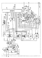
- These and other objects, features and advantages of the present invention will be understood more clearly from the following detailed description with reference to the accompanying drawing, in which the single figure represents a schematic diagram of a preferred embodiment of the invention.
- The direct access test unit, which is to be installed within the central office, has an input access port section and an outgoing trunk section. The input access port section has an input port providing tip T and ring R terminals for connection to a standard ground start line circuit. The tip T and ring R terminals are connected via a rectifier bridge BR1, which forms part of the ring detect
circuit 10, to a standard line transformer T2 of the type typically found in line circuits. A line seize circuit 12 is connected via the rectifier bridge BR1 across the primary windings of the line transformer T2, and a relay K4 is also connected to the primary windings of the line transformer T2 for performing loop current detection. - Four circuits are connected to the secondary windings of the line transformer T2. The first of these circuits is a
DTMF decoder 14 which detects multifrequency dial tones received via the line circuit connected to the tip T and ring R terminals and decodes these tones to the corresponding subscriber line numbers. The second circuit comprises a 440Hz generator 18 which supplies secondary dial tone via theamplifier 16 to indicate to the user that the device is waiting for either a subscriber number entry or a security code entry. The third circuit is aspeech synthesizer circuit 20 which provides various voice messages through theamplifier 16 to guide the user through each test operation and to explain detected error conditions. The fourth circuit is a subscriberline audio monitor 22 which applies audio in scrambled form from a subscriber line under test, when that line is indicated as busy, through the line transformer T2 so that the field technician may monitor the audio. These fourcircuits - The outgoing trunk section of the direct access test unit is provided with an output port including tip T, ring R, sleeve S and ground G terminals to be connected within the central office to a standard no-test trunk circuit, such as a Western Electric Company type 1A 186-01 or equivalent. The tip T and ring R terminals are connected through standard relays L1 and L2 and a rectifier bridge BR2 to the primary windings of line transformer T1. The rectifier bridge BR2 forms part of a trunk seize
circuit 30, which is controlled by the microcomputer 25, and there is also connected across the bridge rectifier BR2 a batteryreverse detection circuit 32. - The secondary windings of the line transformer T1 are connected to the subscriber
line audio monitor 22 and also to amultifrequency generator 36 from which multifrequency signalling is applied through the transformer T1 to the tip and ring leads to the no-test trunk under control of the microcomputer 25. A busy detect circuit 34 is also corrected across the tip T and ring R terminals of the output port to detect a busy condition of the subscriber line under test. Atest function circuit 35 includes various relays which operate to perform the desired tests of the subscriber line accessed through the no-trunk circuit and asleeve control circuit 37 controls communication with the no-test trunk via the sleeve S after the direct access test unit has cut through to the no-test trunk. Finally, a 577HZ generator 38 performs the tests involving the application of high level and low level test tones across the tip and ring leads to the subscriber line under test. - The
speech synthesizer circuit 20, the subscriberline audio monitor 22, themultifrequency generator 36 and the 577Hz generator 38 are controlled by a device selectdecoder 24 in response to a 3-bit code supplied from the microcomputer 25 In this way, these circuits can be selected for operation one at a time under control of the microcomputer 25. - The operation of the direct access test unit will be described with reference to an example in which the field technician is to test a subscriber line A from a remote location where a subscriber line B is available for his use. Accordingly, the field technician will dial the number of the ground start line circuit which is connected to the input port of the direct access test unit using subscriber line B. In this disclosure, references to dealing a subscriber line number and the terms "dealing signals" and "dialed digits" are used in a generic sense to include all standard forms of generating subscriber line designating signals, whether they be dial impulses or multifrequency tones.
- Upon being accessed in this way, the ground start line circuit connected to the tip T and ring R terminals of the input access port of the direct access test unit will apply ringing to the rectifier bridge BR1 in the
ring detector circuit 10. Ringing voltage of more than 55 volts RMS will cause the Zener diode CR1 to conduct, which completes the circuit through the resistance R3 and the optical isolator U1 across the output of the bridge BR1. When the optical isolator U1 is turned on, the capacitor C1 charges, and the signal is supplied through the inverter U2 and line L1 to the microcomputer 25 to indicate that ringing has been detected. The microcomputer 25 responds by applying a signal on line L2, causing the optical isolator U2 in the line seize circuit 12 to turn on, which causes the transistor Q1 to conduct, closing the loop across the incoming tip and ring lines. This causes ring trip in the ground start line circuit. When the line is seized in this way, loop current will be detected by the relay K4 connected to the primary windings of the bridging transformer T2, applying a signal on line L0 to the microcomputer 25 to indicate the detection of loop current. - When the line has been seized and the loop current detected in the manner described above, the microcomputer 25 supplies a 440 Hz square wave to the input of the
generator 18, which is composed of a multiple feedback bandpass filter having a center frequency at 440 Hz and an integrator, for purposes of supplying secondary dial tone through theamplifier 16 and bridging transformer T2 to the line. Upon receiving this secondary dial tone, it is necessary for the field technician to dial a user security code to gain access to use of the test unit, and this user security code, which is stored in the microcomputer 25 should be known to the field technician, if he is authorized to utilize this test unit. If the field technician takes no action at all, the microcomputer will automatically release the line after a certain predetermined time has expired. On the other hand, if the field technician dials the proper user security code, the dialing signals will be received and detected by theDTMF decoder 14, and a four bit digit will be supplied on lines L3-L6 to the microcomputer 25 to identify each digit of the dialed code. The received digits are then compared with the user security code stored within the microcomputer 25 to determine whether the user should be permitted access to the test unit. Detection of the first dialed digit by thedecoder 14 causes the microcomputer 25 to instantly remove the secondary dial tone from the line, as is conventionally done in standard line circuits, and if the digits received by the microcomputer 25 correspond to the authorized user access code, secondary dial tone will be supplied once again from thegenerator 18 to the line to inform the field technician that he has been given access to the test unit. If the received digits do not correspond to the authorized user access code, the secondary dial tone will not be applied to the line for the second time and the field representative will then know that he has either made an error in dialing the access code or has the wrong access code. The microcomputer 25 will permit the user to try again a predetermined number of times to obtain access to the test unit by supplying the proper user access code; however, if this is not achieved within a predetermined number of tries, the microcomputer 25 would automatically release the line. The field representative will then know that he has either made an error in dialing the access code or has the wrong access code. Further, when dialing the user access code, if the first digit of the code is not entred within a certain period of time of receipt of a dial tone, or if too much time elapses between digits, the unit will automatically disconnect. - Assuming that the field technician has dialed the proper user access code and has now received secondary dial tone once again, he should then dial the number of the subscriber line circuit A which he desires to test. If he takes no action for a period of seven seconds for some reason, the microcomputer 25 will select the speech synthesizer circuit via the device
select decoder 24 and apply a strobe signal on line L7 thereto along with address signals selecting a chip from which the voice message "dial seven digit subscriber line number" is read as an audio signal through theamplifier 16. Thus, the voice message, which occurs seven seconds after the start of the second dial tone, informs the user that a seven digit subscriber line number should be dialed at that time. Obviously, if the field technician is familiar with the use of the test unit, he will not need to wait for the voice message, but can immediately begin dialing the seven digit subscriber line number upon receipt of the second dial tone, in which case the microcomputer 25 will not call upon thespeech synthesizer circuit 20. If a digit is not dialed within one minute of receipt of the secondary dial tone, the unit simply disconnects. - The seven digit subscriber line number dialed by the field technician will be detected by the
decoder 14 and the digits will be supplied to the microcomputer 25. Depending upon the particular central office in which the test unit is installed, the microcomputer 25 is programmed to translate the seven digits to four or five digits and to add up to ten different steering digits for those central offices requiring only four or five digits access. To access the subscriber line designated by the received digits, the microcomputer 25 seizes the trunk circuit by outputting a logic high on line L8 to the inverter U3, which inverts this signal and turns on the optical isolator U3 which renders the transistor Q2 conductive, closing the loop across tip and ring on the outgoing trunk, and then selects themultifrequency generator 36 via the deviceselect decoder 24 and supplies thereto a control signal for selecting the frequency pairs which designate the various digits required to identify the subscriber line circuit to be accessed. These multifrequency signals are supplied from thegenerator 36 through the line transformer T1 to the tip and ring lines of the no-test trunk. Reverse battery supervision is detected by thecircuit 32, in which the opto-isolator 34 detects battery reversal and signals this condition to the microcomputer 25 via line L14. - Once the subscriber line circuit to be tested via the no-test trunk has been accessed, the busy detector circuit 34 will determine whether the line circuit is busy by detecting the level of the loop current and the level of the voltage on the ring lead. If the subscriber line is busy, the busy detector circuit 34 will signal this condition to the microcomputer 25 on line L9 and all testing of the subscriber line circuit will be inhibited except for application of the low level simplex tone. At this point, the microcomputer 25 does two things. First of all, it accesses the
speech synthesizer 20 via the deviceselect decoder 24 and applies the strobe signal on line L7 along with the address signals necessary to read out the voice message "busy line" to the user via theamplifier 16 and line transformer T2. At the same time, the audio monitor test function is automatically invoked by the microcomputer 25, which selects the subscriberline audio monitor 22 via the deviceselect decoder 24. The subscriberline audio monitor 22 receives the audio on the accessed subscriber line via the line transformer T1, scrambles it and applies the scrambled audio directly to the line transformer T2 so that the field technician can monitor this scrambled audio signal. The field technician may also dial a single digit to provide application of the low level simplex tone to the subscriber line, which is the only test not disabled under these conditions, but attempts to initiate other tests of the busy circuit will simply result in a repeat of the voice message "busy line". At the end of one minute of monitoring the busy line, the unit will automatically return to the test mode and a voice message will be generated to indicate the options available as will be explained later. - If the subscriber line being accessed is found to be not busy, the microcomputer 25 will again access the
speech synthesizer circuit 20 via the deviceselect decoder 24 and apply the strobe signal on line L7 along with proper addresses to read out a voice message "OK". This voice message indicates to the field technician that access has been made to the designated subscriber line, which has been found to be idle. The field technician may then dial a single digit to select a particular test to be performed with respect to the subscriber circuit, and he will do so immediately if he is familiar with the test unit and its operation. If no digit is dialed by the field technician within seven seconds of the "OK" voice message, the microcomputer 25 will again enable thespeech synthesizer circuit 20 to read out a series of voice messages listing the different test functions that may be performed by dialing various digits. An example of such voice messages is indicated below:
DIAL TWO FOR AUDIO MONITOR
DIAL FOUR FOR HIGH LEVEL TONE
DIAL FIVE FOR LOW LEVEL TONE
DIAL SIX TO OPEN SUBSCRIBER LINE
DIAL SEVEN TO SHORT SUBSCRIBER LINE
DIAL STAR TO KEEP TEST AFTER DISCONNECT
DIAL POUND FOR NEW SUBSCRIBER LINE
The field technician may then select one of the test functions to be initiated and dial the appropriate digit. Each time a test function is started in response to a digit dialed by the field technician, the microcomputer 25 will cause thespeech synthesizer circuit 20 to issue a voice message identifying that test function, such as "audio monitor", "high level tone", "low level tone", "open line" and "short line". After selection of the hold test utility function, the voice message "dial number of minutes" will be read out, and the field technician is expected to dial a single digit to designate the number of minutes the test currently in progress is to remain in effect after disconnect. Thus, while the test unit normally will disconnect immediately when the subscriber goes on hook, the unit has the capability of continuing a test function from one to ten minutes after going on hook, if so instructed. - After each of the test functions initiated by the field technician and receipt of the appropriate voice message identifying that test function, the field technician may then dial another digit to select a new test or utility function. In addition, as apparent from the foregoing list of voice messages relating to test functions, when the field technician completes the testing of a particular subscriber line, it is not necessary for him to disconnect from the test unit in order to access another subscriber line for testing. After receiving a voice message acknowledging the completion of any test, the field technician can simply dial POUND for a new subscriber line, and the microcomputer 25 will place secondary dial tone from the
generator 18 on the line indicating that the unit is prepared to receive the dialed digits relating to a new subscriber line. - The various test functions are performed by selectively operating the relays K1, K3 and K3 in the
test function circuit 35 from the microcomputer 25. To perform an open test on the subscriber line, the microcomputer 25 places a high on line L10 to the inverter I₄ so as to operate the relay K1 which opens the tip and ring lines connected from the rectifier bridge BR2 to the tip T and ring R terminals of the output port. To perform a short test, the microcomputer 25 places a high on line L11 to the inverter I5 so as to operate the relay K2. This places a short across the tip and ring lines to the trunk circuit so that a short test of the DC resistance can be made. - To perform the low level or high level tone test, the microcomputer 25 selects the 577 Hz
generator 38 via the deviceselect decoder 24. For a low level tone test, the microcomputer 25 maintains a low on the line L12 to the inverter I6 so as to maintain the relay K3 unenergized. The low level tone will then be applied from thegenerator 38 across tip and ring to perform the longitudinal simplex low level tone test which will not disturb traffic on a busy line. To perform the differential high level tone test, the microcomputer 25 places a high on line L12 while thegenerator 38 is selected so as to energize the relay K3 via the inverter I6. This places the high level tone across tip and ring to the trunk circuit. - The test unit has two current level control, i.e., both high and low, on the sleeve to the no-test trunk. After the test unit cuts through to the test trunk, it communicates with the trunk via the sleeve current. For the low current state, the microcomputer 25 maintains a low on the line L13 so that current on the sleeve will pass both through resistor R4 and resistor R5. In the high current state, however, the microcomputer 25 will place a high on line L13 to the inverter I7, so that current passes only through the resistor R5, bypassing the resistor R4.
- The test unit may also be programmed for those subscriber line prefixes which will be used in the testing of line circuits. For this purpose, a predetermined number of three-digit prefixes can be stored in the memory of the microcomputer 25. If an attempt is made during subscriber line number entry to use a prefix that has not been programmed, the unit will respond with an error message.
- The microcomputer 25 is a conventional device including a microprocessor and non-volatile memory for storing of data and programs necessary to perform the functions described herein. In addition to controlling the overall operation of the direct access test unit, the microcomputer 25 performs certain housekeeping tasks, such as maintaining a count of the various accesses to the unit, storing of data relating to subscriber lines to be accessed, storing the required security codes and maintaining a listing of the identification of prefixes to be used for the different tests capable of being initiated by the test unit.
- In addition to accessing subscriber lines and initiating various designated tests with respect to these lines, it is also possible to access the test unit for purposes of changing the data stored therein relating to security access codes, the prefixes utilized to identify the test functions and to obtain access to the various counters for obtaining a reading of the data therein. For this purpose, the field technician simply dials the number of the ground start line circuit connected to the input port of the test unit in the same manner already described, but upon initial receipt of the secondary dial tone, instead of dialing a user security code, the field technician will dial a system security code. The microcomputer 25 will respond to a correctly dialed system security code by reading out from the
speech synthesizer circuit 20 the message "OK". In response to this voice message, the field technician can then dial a single digit to select a particular programming function. If he does not do so within seven seconds after the "OK" message, the microcomputer 25 will automatically read out a series of voice messages identifying the different single digits which will initiate various programming functions. An example of such voice messages is listed below:
DIAL ONE TO CHANGE SYSTEM SECURITY CODE
DIAL TWO TO CHANGE USER SECURITY CODE
DIAL THREE TO ADD PREFIX
DIAL FOUR TO CLEAR ALL PREFIXES
DIAL FIVE TO SET NUMBER OF DIGITS TO ACCESS SUBSCRIBER LINE
DIAL SIX TO READ PREFIXES
DIAL SEVEN TO READ ACCESS COUNTER
DIAL EIGHT TO READ JOB COUNTER
DIAL NINE TO CLEAR ALL COUNTERS
DIAL ZERO TO CLEAR ALARM
DIAL STAR TO SELECT DIALING METHOD
The field technician may then proceed to select one of the programming functions by dialing a single digit corresponding to that programming function. As can be seen, it is possible to change the system security code or the user security code, to add a prefix, to clear all prefixes, to set the number of digits required to access a subscriber line (for a particular central office), to read the prefixes, to read the access counter, to read the job counter, to clear all counters, to clear an alarm, and to select a dialing method. As in the case of initiating test functions relating to a subscriber line circuit, after each programming function is selected, the microcomputer 25 will cause thespeech synthesizing circuit 20 to read out a voice message identifying that programming function or indicating the next operation to be performed by the field technician to complete the selected programming function. - As can be seen from the foregoing description, the present invention provides a direct access test unit which allows the field technician to access any line circuit within the central office through a single designated line circuit connected to the input port of the test device while he is trying to trouble-shoot a problem. In this way, he bypasses all of the normal personnel previously required to perform such tests through the central office, thereby facilitating more complete automation of the central office. A considerable saving in the time required for the testing of line circuits also results from the fact that the field technician does not need to initiate a new connection to the central office each time a new subscriber line is to be tested. Rather, once access has been obtained to the direct access test unit, it is possible to test a succession of lines without going on hook and dialing the new subscriber line for each line to be tested. It has been estimated that as much as 15 minutes may be saved for every test call that the field technician makes in the course of trouble-shooting a particular problem.
- In addition, the provision of voice messages to guide the user through each test operation or explain errors in the operations performed by the field technician permit even those not particularly skilled with this type of equipment to use it effectively.
- While we have shown and described only one embodiment in accordance with the present invention, it is understood that the same is not limited thereto but is susceptible of numerous changes and modifications as known to one having ordinary skill in the art and we therefore do not wish to be limited to the details shown and described herein, but intend to cover all such modifications as are encompassed by the scope of the appended claims.
Claims (19)
- A direct access test unit to be connected in a central office for testing subscriber lines has an input access port and an output access port, a generator for generating dialing signals and a processor for controlling the generator, whereby the output access port has tip, ring, sleeve and ground terminals for connection to a test trunk circuit in the central office, characterized in, that the input access port (10, 12) has tip (T) and ring (R) terminals for connection to a line circuit in a central office and wherein there is provided decoder means (14) connected to the input access port (10, 12) for detecting and decoding the dialing signals indicating a designated subscriber line and received from a remote location via said line circuit; said processor (25) including control means responsive to the decoded dialing signals received from the decoder means (14) for connecting the generator (36) to the output access port and for controlling the generator (36) to generate dialing signals indicating the designated subscriber line.
- A direct access test unit according to claim 1, further including test circuit means (35) connected to said output access port and controlled by said processor control means for performing selected tests on said designated subscriber line in response to commands received from said remote location via said line circuit and said input access port.
- A direct access test unit according to claim 2, wherein said test circuit means includes means (I5) responsive to a control signal from said processor control means for connecting a short circuit (K2) across said tip and ring terminals of said output access port.
- A direct access test unit according to claim 2, wherein said test circuit means includes means (38) responsive to a control signal from said processor control means for applying a test tone signal (K3) across said tip and ring terminals of said output access port.
- A direct access test unit according to claim 4, wherein said test tone signal applying means is capable of selectively generating high or low level tone signals under control of said processor control means.
- A direct access test unit according to claim 2, wherein said test circuit means includes means (I4) responsive to a control signal from said processor control means for producing an open circuit condition (K1) from said output access port to said designated subscriber line via said test trunk circuit.
- A direct access test unit according to claim 1, further including sleeve control means responsive to a control signal from said processor control means for controlling the current at the sleeve terminal of said output access port.
- A direct access test unit according to claim 2, wherein said processor control means includes means responsive to said decoder means detecting and decoding dialing signals representing at least one digit from said remote location for controlling said test circuit means to perform a selected test designated by said dialing signals on said designated subscriber line.
- A direct access test unit according to claim 1, further including speech synthesizing means (20) responsive to control signals from said processor control means for applying selected voice messages through said input access port.
- A direct access test unit according to claim 9, wherein said processor means includes means responsive to said decoder means detecting and decoding dialing signals representing at least one digit from said remote location for controlling said speech synthesizer to apply a selected voice message to said input access port.
- A direct access test unit according to claim 9, wherein said voice messages include instructions for initiating the testing of a selected subscriber line circuit via said output access port.
- A direct access test unit according to claim 9, further including test circuit means connected to said output access port and controlled by said processor control means for performing selected tests on said designated subscriber line in response to commands received from said remote location via said line circuit and said input access port.
- A direct access test unit according to claim 12, wherein said voice messages include information relating to the status of tests performed by said test circuit means.
- A direct access test unit according to claim 2, further including ring detector means (10) connected to said input access port for detecting ringing voltage received from said line circuit, a voice bridge transformer for conducting dialing signals to said decoder means, line seize means (12) for selectively connecting said voice bridge transformer to said input access port and dial tone generator means for generating a dial tone signal, said processor control means including means responsive to said ring detector means detecting a ringing voltage for actuating said line seize means to connect said voice bridge transformer to said input access port and for actuating said dial tone generator means to apply said dial tone signal through said voice bridge transformer to said input access port.
- A direct access test unit according to claim 14, further including busy detect means (34) connected to said tip and ring terminals for detecting a busy condition in a subscriber line connected to said output access port via said test trunk and audio monitor means (22) for selectively supplying audio signals received from said output access port to said voice bridge transformer to permit said audio signals to be monitored at said remote location, said processor control means including means responsive to said busy detect means for enabling said audio monitor means to supply said audio signals to said remote location when said designated subscriber line is busy.
- A direct access test unit according to claim 15, wherein said audio monitor means includes means for scrambling said audio signals so as to render them unintelligible at some remote location.
- A direct access test unit according to claim 14, wherein said processor control means includes means for releasing said line seize means if dialing signals representing a predetermined access code are not detected by said decoder means a predetermined time after said dial tone signal has been applied to said input access port in response to detection of ringing voltage by said ring detector means.
- A direct access test unit according to claim 14, wherein said processor control means includes means responsive to detection and decoding by said decoder means of dialing signals received at sequential intervals and identifying different subscriber lines for controlling said generator means to generate dialing signals at said sequential intervals identifying said different subscriber lines without releasing said line seize means.
- A direct access test unit according to claim 1, wherein said processor control means includes means responsive to dialing signals representing a certain number of digits indicating a designated subscriber line, as detected and decoded by said decoder means, for controlling said generator means to generate dialing signals representing a different number of digits which also indicate the same designated subscriber line.
Priority Applications (1)
| Application Number | Priority Date | Filing Date | Title |
|---|---|---|---|
| AT87900940T ATE77186T1 (en) | 1986-01-03 | 1987-01-05 | DIRECT ACCESS TEST UNIT FOR TELEPHONE SWITCHING. |
Applications Claiming Priority (2)
| Application Number | Priority Date | Filing Date | Title |
|---|---|---|---|
| US816158 | 1986-01-03 | ||
| US06/816,158 US4670898A (en) | 1986-01-03 | 1986-01-03 | Direct access test unit for central office |
Publications (3)
| Publication Number | Publication Date |
|---|---|
| EP0253871A1 EP0253871A1 (en) | 1988-01-27 |
| EP0253871A4 EP0253871A4 (en) | 1988-05-10 |
| EP0253871B1 true EP0253871B1 (en) | 1992-06-10 |
Family
ID=25219830
Family Applications (1)
| Application Number | Title | Priority Date | Filing Date |
|---|---|---|---|
| EP87900940A Expired EP0253871B1 (en) | 1986-01-03 | 1987-01-05 | Direct access test unit for central office |
Country Status (3)
| Country | Link |
|---|---|
| US (1) | US4670898A (en) |
| EP (1) | EP0253871B1 (en) |
| WO (1) | WO1987004308A1 (en) |
Families Citing this family (25)
| Publication number | Priority date | Publication date | Assignee | Title |
|---|---|---|---|---|
| US4764949A (en) * | 1987-05-28 | 1988-08-16 | Harris Corp. | Subscriber/craftsperson ringback apparatus |
| US4841560A (en) * | 1987-10-16 | 1989-06-20 | Harris Corp. | Direct access test unit for central office |
| DE3890881T1 (en) * | 1987-10-16 | 1989-12-21 | Harris Corp | TEST UNIT FOR TESTING TELEPHONE LINES |
| US4887289A (en) * | 1988-08-29 | 1989-12-12 | New York Telephone Company | Remote testing of a trunk leading to an automatic call distributor |
| US5432705A (en) * | 1991-05-31 | 1995-07-11 | Itronix Corporation | Administrative computer and testing apparatus |
| US5353327A (en) * | 1992-05-04 | 1994-10-04 | At&T Bell Laboratories | Maintenance termination unit |
| US5355405A (en) * | 1992-06-26 | 1994-10-11 | At&T Bell Laboratories | Arrangement for dynamically identifying the assignment of a subscriber telephone loop connection at a serving terminal |
| JP3069440B2 (en) * | 1992-06-30 | 2000-07-24 | 富士通株式会社 | Centralized monitoring system for subscriber line multiplex transmission system. |
| GB9406212D0 (en) * | 1994-03-29 | 1994-05-18 | Plessey Telecomm | Telecommunication customer interface |
| US5633909A (en) * | 1994-06-17 | 1997-05-27 | Centigram Communications Corporation | Apparatus and method for generating calls and testing telephone equipment |
| IES950326A2 (en) * | 1995-05-09 | 1995-10-04 | Markton Limited | "Apparatus for providing access to a line test device for testing a characteristic of a telephone line of a telephone network" |
| US6385299B1 (en) | 1995-09-12 | 2002-05-07 | British Telecommunications Public Limited Company | Line testing in a telecommunications network |
| AU6938896A (en) | 1995-09-12 | 1997-04-01 | British Telecommunications Public Limited Company | Line testing in a telecommunications network |
| US5940471A (en) * | 1996-10-04 | 1999-08-17 | Northern Telecom Limited | Method and apparatus for obtaining feedback regarding network services |
| US5974115A (en) * | 1996-11-15 | 1999-10-26 | Bellsouth Intellectual Property Managment Corporation | System and method for testing subscriber lines and terminating equipment from a service platform |
| US6002746A (en) * | 1997-04-16 | 1999-12-14 | British Telecommunications Public Limited Company | Line testing in a telecommunications network |
| AUPO694997A0 (en) * | 1997-05-22 | 1997-06-12 | Teletech Pty. Ltd. | Remote testing of a communications line |
| KR100258150B1 (en) * | 1997-05-29 | 2000-06-01 | 윤종용 | Method and circuit for channel assign trunk line test in rf communication system |
| US6438212B1 (en) | 1997-09-18 | 2002-08-20 | Verizon Services Corp. | Automated telephone line test apparatus with intelligent diagnostic function |
| US6233558B1 (en) | 1998-02-11 | 2001-05-15 | Tempo Research Corporation | Method and apparatus for simultaneous tracing of multiple transmission lines |
| US6078646A (en) * | 1999-09-22 | 2000-06-20 | Mclaughlin; Peter J. | Caller ID activated test device for testing a telephone subscriber loop/access line |
| CN1452833A (en) * | 2000-06-02 | 2003-10-29 | 富士通株式会社 | Communication device and access network device |
| US7394980B1 (en) * | 2001-01-11 | 2008-07-01 | Sprint Communications Company L.P. | Systems and methods for testing a circuit in a communication network |
| US7149285B2 (en) * | 2002-10-02 | 2006-12-12 | Fluke Corporation | Dynamic, automated double-ended system and method for testing and qualifying metallic telecommunication loops |
| US20040086086A1 (en) * | 2002-10-30 | 2004-05-06 | Butler Myron C. | Automated subscriber loop identification and data transfer for subscriber loop testing |
Family Cites Families (3)
| Publication number | Priority date | Publication date | Assignee | Title |
|---|---|---|---|---|
| US4029913A (en) * | 1976-03-31 | 1977-06-14 | Magnetic Controls Company | Remote accessing system for telephone lines |
| GB2072460B (en) * | 1980-03-20 | 1984-01-25 | Standrad Telephones & Cables L | Telephone exchange test apparatus |
| US4438298A (en) * | 1982-07-16 | 1984-03-20 | Bell Telephone Laboratories, Incorporated | System for accessing and testing subscriber loops |
-
1986
- 1986-01-03 US US06/816,158 patent/US4670898A/en not_active Expired - Lifetime
-
1987
- 1987-01-05 WO PCT/US1987/000043 patent/WO1987004308A1/en not_active Ceased
- 1987-01-05 EP EP87900940A patent/EP0253871B1/en not_active Expired
Also Published As
| Publication number | Publication date |
|---|---|
| EP0253871A4 (en) | 1988-05-10 |
| EP0253871A1 (en) | 1988-01-27 |
| US4670898A (en) | 1987-06-02 |
| WO1987004308A1 (en) | 1987-07-16 |
Similar Documents
| Publication | Publication Date | Title |
|---|---|---|
| US4670898A (en) | Direct access test unit for central office | |
| US4841560A (en) | Direct access test unit for central office | |
| US4748654A (en) | Remote supervisory monitoring and control system | |
| US4807279A (en) | Remotely programmable call forwarding control device | |
| US5339351A (en) | Emergency response system | |
| US4154988A (en) | Method and means for accessing program memory of a common control telecommunications switching system | |
| EP0823182B1 (en) | Least cost router | |
| US5029290A (en) | Emergency alert system | |
| CA2233294C (en) | A telecommunications switch | |
| US4219700A (en) | Partyline subscriber interface circuit | |
| US6366647B1 (en) | Alarm report call rerouter | |
| US4864597A (en) | Cable pair tester | |
| US3046339A (en) | Morning call system | |
| US5978461A (en) | Telephone switching system with internal and external channel | |
| DE3779697T2 (en) | TEST UNIT WITH DIRECT ACCESS FOR TELEPHONE TRANSMISSION. | |
| US5065424A (en) | Apparatus for servicing telephones from a remote location | |
| JPS6345946A (en) | Communication equipment | |
| JP3942221B2 (en) | Automatic switching equipment line failure determination device | |
| KR970003418B1 (en) | Fax interface device for remote control of receive mode | |
| JP3415224B2 (en) | Key telephone equipment | |
| JPH08307321A (en) | Data transmission system | |
| JPS62235860A (en) | Communication control equipment | |
| JPH04372255A (en) | Line connection tester | |
| JPS6314554A (en) | Faulty call obstacle detecting system | |
| JPH0738659B2 (en) | Communication line divider |
Legal Events
| Date | Code | Title | Description |
|---|---|---|---|
| PUAI | Public reference made under article 153(3) epc to a published international application that has entered the european phase |
Free format text: ORIGINAL CODE: 0009012 |
|
| AK | Designated contracting states |
Kind code of ref document: A1 Designated state(s): AT BE CH DE FR GB IT LI LU NL SE |
|
| 17P | Request for examination filed |
Effective date: 19880112 |
|
| D17P | Request for examination filed (deleted) | ||
| R17P | Request for examination filed (corrected) |
Effective date: 19880310 |
|
| RAP1 | Party data changed (applicant data changed or rights of an application transferred) |
Owner name: HARRIS CORPORATION |
|
| RIN1 | Information on inventor provided before grant (corrected) |
Inventor name: COFFELT, STEVEN R. Inventor name: CHAN, AARON Inventor name: CURTIN, LEONARD E. Inventor name: PIERCE, BEN A. |
|
| A4 | Supplementary search report drawn up and despatched |
Effective date: 19880510 |
|
| 17Q | First examination report despatched |
Effective date: 19901026 |
|
| ITTA | It: last paid annual fee | ||
| GRAA | (expected) grant |
Free format text: ORIGINAL CODE: 0009210 |
|
| AK | Designated contracting states |
Kind code of ref document: B1 Designated state(s): AT BE CH DE FR GB IT LI LU NL SE |
|
| PG25 | Lapsed in a contracting state [announced via postgrant information from national office to epo] |
Ref country code: LI Effective date: 19920610 Ref country code: CH Effective date: 19920610 |
|
| REF | Corresponds to: |
Ref document number: 77186 Country of ref document: AT Date of ref document: 19920615 Kind code of ref document: T |
|
| REF | Corresponds to: |
Ref document number: 3779697 Country of ref document: DE Date of ref document: 19920716 |
|
| ITF | It: translation for a ep patent filed | ||
| REG | Reference to a national code |
Ref country code: CH Ref legal event code: PL |
|
| ET | Fr: translation filed | ||
| PGFP | Annual fee paid to national office [announced via postgrant information from national office to epo] |
Ref country code: SE Payment date: 19921211 Year of fee payment: 7 |
|
| PGFP | Annual fee paid to national office [announced via postgrant information from national office to epo] |
Ref country code: LU Payment date: 19921218 Year of fee payment: 7 |
|
| PGFP | Annual fee paid to national office [announced via postgrant information from national office to epo] |
Ref country code: BE Payment date: 19921223 Year of fee payment: 7 |
|
| PGFP | Annual fee paid to national office [announced via postgrant information from national office to epo] |
Ref country code: GB Payment date: 19921231 Year of fee payment: 7 |
|
| PGFP | Annual fee paid to national office [announced via postgrant information from national office to epo] |
Ref country code: NL Payment date: 19930131 Year of fee payment: 7 |
|
| EPTA | Lu: last paid annual fee | ||
| PLBE | No opposition filed within time limit |
Free format text: ORIGINAL CODE: 0009261 |
|
| STAA | Information on the status of an ep patent application or granted ep patent |
Free format text: STATUS: NO OPPOSITION FILED WITHIN TIME LIMIT |
|
| 26N | No opposition filed | ||
| PG25 | Lapsed in a contracting state [announced via postgrant information from national office to epo] |
Ref country code: LU Free format text: LAPSE BECAUSE OF NON-PAYMENT OF DUE FEES Effective date: 19940105 Ref country code: GB Effective date: 19940105 |
|
| PG25 | Lapsed in a contracting state [announced via postgrant information from national office to epo] |
Ref country code: SE Effective date: 19940106 |
|
| PG25 | Lapsed in a contracting state [announced via postgrant information from national office to epo] |
Ref country code: BE Effective date: 19940131 |
|
| PGFP | Annual fee paid to national office [announced via postgrant information from national office to epo] |
Ref country code: FR Payment date: 19940613 Year of fee payment: 8 |
|
| PGFP | Annual fee paid to national office [announced via postgrant information from national office to epo] |
Ref country code: AT Payment date: 19940614 Year of fee payment: 8 |
|
| PGFP | Annual fee paid to national office [announced via postgrant information from national office to epo] |
Ref country code: DE Payment date: 19940615 Year of fee payment: 8 |
|
| BERE | Be: lapsed |
Owner name: HARRIS CORP. Effective date: 19940131 |
|
| PG25 | Lapsed in a contracting state [announced via postgrant information from national office to epo] |
Ref country code: NL Effective date: 19940801 |
|
| GBPC | Gb: european patent ceased through non-payment of renewal fee |
Effective date: 19940105 |
|
| NLV4 | Nl: lapsed or anulled due to non-payment of the annual fee | ||
| PG25 | Lapsed in a contracting state [announced via postgrant information from national office to epo] |
Ref country code: AT Effective date: 19950105 |
|
| EUG | Se: european patent has lapsed |
Ref document number: 87900940.5 Effective date: 19940810 |
|
| PG25 | Lapsed in a contracting state [announced via postgrant information from national office to epo] |
Ref country code: FR Effective date: 19950929 |
|
| PG25 | Lapsed in a contracting state [announced via postgrant information from national office to epo] |
Ref country code: DE Effective date: 19951003 |
|
| REG | Reference to a national code |
Ref country code: FR Ref legal event code: ST |
|
| PG25 | Lapsed in a contracting state [announced via postgrant information from national office to epo] |
Ref country code: IT Free format text: LAPSE BECAUSE OF NON-PAYMENT OF DUE FEES Effective date: 20050105 |