EP0253482B1 - Measuring adjacent channel power - Google Patents
Measuring adjacent channel power Download PDFInfo
- Publication number
- EP0253482B1 EP0253482B1 EP87304843A EP87304843A EP0253482B1 EP 0253482 B1 EP0253482 B1 EP 0253482B1 EP 87304843 A EP87304843 A EP 87304843A EP 87304843 A EP87304843 A EP 87304843A EP 0253482 B1 EP0253482 B1 EP 0253482B1
- Authority
- EP
- European Patent Office
- Prior art keywords
- signal
- adjacent channel
- low pass
- pass filter
- measuring
- Prior art date
- Legal status (The legal status is an assumption and is not a legal conclusion. Google has not performed a legal analysis and makes no representation as to the accuracy of the status listed.)
- Expired - Lifetime
Links
- 238000001228 spectrum Methods 0.000 claims description 13
- 238000001914 filtration Methods 0.000 claims description 7
- 238000000034 method Methods 0.000 claims description 5
- 230000000737 periodic effect Effects 0.000 claims description 4
- 230000005540 biological transmission Effects 0.000 description 15
- 230000008878 coupling Effects 0.000 description 10
- 238000010168 coupling process Methods 0.000 description 10
- 238000005859 coupling reaction Methods 0.000 description 10
- 238000005259 measurement Methods 0.000 description 8
- 230000000694 effects Effects 0.000 description 5
- 230000001427 coherent effect Effects 0.000 description 3
- 238000010408 sweeping Methods 0.000 description 3
- 238000006243 chemical reaction Methods 0.000 description 2
- 238000013461 design Methods 0.000 description 2
- 238000003780 insertion Methods 0.000 description 2
- 230000037431 insertion Effects 0.000 description 2
- 230000003321 amplification Effects 0.000 description 1
- 239000003990 capacitor Substances 0.000 description 1
- 239000000919 ceramic Substances 0.000 description 1
- 239000013078 crystal Substances 0.000 description 1
- 238000001514 detection method Methods 0.000 description 1
- 238000003199 nucleic acid amplification method Methods 0.000 description 1
- 230000005236 sound signal Effects 0.000 description 1
- 230000003595 spectral effect Effects 0.000 description 1
- 230000001360 synchronised effect Effects 0.000 description 1
- 238000012360 testing method Methods 0.000 description 1
Images



Classifications
-
- G—PHYSICS
- G01—MEASURING; TESTING
- G01R—MEASURING ELECTRIC VARIABLES; MEASURING MAGNETIC VARIABLES
- G01R21/00—Arrangements for measuring electric power or power factor
- G01R21/10—Arrangements for measuring electric power or power factor by using square-law characteristics of circuit elements, e.g. diodes, to measure power absorbed by loads of known impedance
-
- G—PHYSICS
- G01—MEASURING; TESTING
- G01R—MEASURING ELECTRIC VARIABLES; MEASURING MAGNETIC VARIABLES
- G01R21/00—Arrangements for measuring electric power or power factor
-
- H—ELECTRICITY
- H04—ELECTRIC COMMUNICATION TECHNIQUE
- H04B—TRANSMISSION
- H04B17/00—Monitoring; Testing
- H04B17/10—Monitoring; Testing of transmitters
- H04B17/101—Monitoring; Testing of transmitters for measurement of specific parameters of the transmitter or components thereof
- H04B17/104—Monitoring; Testing of transmitters for measurement of specific parameters of the transmitter or components thereof of other parameters, e.g. DC offset, delay or propagation times
-
- H—ELECTRICITY
- H04—ELECTRIC COMMUNICATION TECHNIQUE
- H04B—TRANSMISSION
- H04B17/00—Monitoring; Testing
- H04B17/10—Monitoring; Testing of transmitters
- H04B17/15—Performance testing
- H04B17/18—Monitoring during normal operation
Definitions
- This invention relates to adjacent channel power of signal sources.
- it relates to a method and apparatus for measuring the adjacent channel power of, for instance, a transmitter.
- Adjacent channel power is usually measured over a bandwidth equivalent to that of a typical receiver, which varies upon the type of transmission i.e., single sideband (SSB), frequency modulation (FM), etc.
- SSB single sideband
- FM frequency modulation
- the adjacent channel is nominally 2.4kHz wide, separated by 5kHz from the main transmission channel.
- such measurements are made by firstly down converting the transmitter signal to a suitable intermediate frequency, i.f..
- the signal is subsequently passed through a bandpass filter centered on the adjacent channel to be measured, and having well defined characteristics.
- the bandpass filter may have typically a 6dB bandwidth of 2,400Hz.
- Steep skirts are required to substantially reject signals outside the required bandwidth, including of course the main transmission signal.
- the filter must therefore be different for each type of transmission, must be environmentally stable, and requires a very high Q. They are usually ceramic, crystal or mechanical filters. As a result they can be expensive to produce and test and a different design is required for each transmission system.
- the downconverted signal is passed through a low pass filter prior to synchronous detection, and the power output of the detected signals is measured. In both proposals, the measurements of adjacent channel power are made at i.f..
- a method for measuring adjacent channel power of a signal source including down converting a signal; filtering the down converted signal with a low pass filter; measuring the power output of the signal after filtering by the low pass filter; characterised in that the downconversion of the signal is such that the adjacent channel band is converted to base band.
- the meters used to measure the power output must be a.c. coupled in order not to measure d.c. offsets from the filter and amplifiers. As is also described below this leads to an unwanted notch in the filter characteristics.
- the invention also provides a method, and apparatus for measuring adjacent channel power of a signal source including the steps of mixing an input signal with a local oscillator signal having angle modulation and which is nominally centered on the desired adjacent channel centre frequency so that the adjacent channel band is down converted to base band; filtering the down converted signal with a low pass filter; and measuring the power output from the low pass filter by means of an a.c. coupled meter.
- the local oscillator is modulated by phase or frequency modulation which may be from a noise source, and the low pass filter has a frequency response substantially equal to half the adjacent channel bandwidth.
- the noise may be restricted in bandwidth and frequency and may for example have a 50Hz bandwidth and a r.m.s deviation of 50Hz.
- the output signal from the low pass filter may be amplified and measured by a volt meter and a value obtained for the power, either absolute or relative, of the adjacent channel.
- the low pass filter may have a bandwidth significantly less than the adjacent channel bandwidth. Typically this might be 100Hz.
- the local oscillator frequency may be swept by a periodic waveform, such that parts of the desired adjacent channel frequency spectrum are passed in turn by the low pass filter.
- the periodic waveform may be a triangular wave.
- the output from the low pass filter may be arithmetically squared and measured by an integrating type volt meter adapted to measure the output voltage over one or more complete cycles of the local oscillator sweep waveform. The output from the volt meter is then a measure of the adjacent channel power.
- FIG. 1 A typical output spectrum from an rf transmitter is shown at Figure 1. It is seen that although the main power is concentrated at the desired transmitter channel frequency there is still a measurable signal power at the adjacent frequencies. In a typical SSB (single side band) transmission the adjacent channel is 2.4kHz wide and separated by 5kHz from the transmission channel. Apparatus to measure the adjacent channel power must therefore be arranged to measure the full power in a 2.4kHz bandwidth and to substantially reject those components of the signal outside this bandwidth.
- SSB single side band
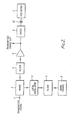
- FIG. 2 shows one apparatus which may be used to achieve this aim.
- the transmitter signal 1 is mixed in a mixer 2 with the output of an oscillator 3 whose frequency is nominally at the centre of the adjacent channel to be measured.
- the transmitter signal input to the mixer may be an intermediate frequency (i.f.) signal generated by frequency conversion of the transmitter signal if desired.
- Filter 4 removes the high frequency component and thus the output from the filter is down-converted to a baseband signal, as is shown in Figure 3.
- the main transmitter signal appears as an audio signal centered at the adjacent channel offset frequency, 5kHz.
- the adjacent channel signal spectrum is "folded" over so that for an SSB transmission having a channel bandwidth of 2.4kHz the adjacent channel power is located between 0Hz, i.e. dc, and 1.2kHz.
- the output from filter 4 is then amplified by amplifier 5 and filtered by a low pass filter 6 having a bandwidth substantially that required by the adjacent channel filter specification.
- the output from filter 6 is measured by voltmeter 7.
- the amplifiers used to recover the adjacent channel power from the 1.2kHz low pass filter must be a.c. coupled.
- a coupling network is shown schematically in the Figure by capacitor 32.
- the voltmeter may include several coupling networks.
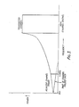
- the a.c coupling results in the effective adjacent channel power filter response being as shown in Figure 4. Due to the ac coupling, there will be a notch in the filter characteristics at 0Hz since dc is not of course transmitted.
- the ac coupling networks are 3dB down at, for example, 5Hz, a notch with a -3dB bandwidth 10Hz will appear as shown. This is overcome in the first embodiment of the present invention by applying modulation to the local oscillator. This may be frequency or phase modulation.
- the angle modulation should preferably be provided by noise.
- noise may typically be noise filtered by a low pass filter with 50Hz bandwidth and an r.m.s deviation of 50Hz.
- the angle modulation serves to smear out the notch in the equivalent adjacent channel power filter and leaves a slight pass band dip in the centre of the filter characteristics as shown in Figure 5.
- the width and depth of the dip are controlled by the deviation of the angle modulation.
- a coherent signal which would, without angle modulation, be located in the filter notch caused by the ac coupling networks. Without angle modulation, the volt meter would not respond to the signal.
- the down converted signal is frequency modulated and hence only spends a fraction of the time at a frequency within the notch. The volt meter will therefore measure this signal although with a slightly reduced amplitude since it does appear within the notch for a small fraction of the time.
- the angle modulation can be chosen such that the slight dip is well within the allowed pass band ripple of the filter and hence the resulting errors are within allowable limits.
- a low pass filter is implemented as a seven pole, 6 zero elliptic filter with 0.01dB pass band ripple. This filter is of high order and therefore complex but can be implemented as an active filter, the design of which may be made by methods well known in the art.
- the apparatus may include a number of alternative low pass filters which may be switched in and out and the local oscillator frequency may be adjusted to cope with different adjacent channel bandwidths.
- the voltmeter 7 measures the signal passed by low pass filter 6.
- the insertion loss of the mixer and any network between the transmitter and mixer must be taken into account. It is often more useful to measure the relative adjacent channel power relative to the transmitted power. All that is required in the present apparatus is to measure the transmitted signal power before the low pass filter 6 and compare this to the adjacent channel power after the filter.
- a second apparatus according to the invention for measuring adjacent channel power is shown in Figure 6.
- an input signal 21 is down converted in a mixer 22 by mixing with a local oscillator 23 whose frequency is set nominally to be the centre of the adjacent channel to be measured.
- a local oscillator 23 whose frequency is set nominally to be the centre of the adjacent channel to be measured.
- the adjacent channel is 2.4kHz wide, 6dB down, and separated by 5kHz from the transmission channel.
- the mixer 22 incorporates a wide bandwidth low pass filter which removes the unwanted spurious products.
- the signal from down conversion mixer 22 is filtered by a low pass filter 26 whose bandwidth is significantly less than the adjacent channel bandwidth and might be for instance 100Hz.
- the output from low pass filter 26 is fed by means of an ac coupling network 27 to a squaring circuit 28 whose output voltage Vn2, is the square of its input voltage Vn, and the output from this measured by an integrating type of volt meter 29.
- the frequency of local oscillator 23 is swept by a triangular waveform generated by waveform generator 30 so that the frequency varies periodically about its nominal frequency.
- the output from generator 30 is also fed as a controlling signal to integrating volt meter 29 such that the output voltage from squaring circuit 28 is measured over one or more complete cycles of the local oscillator sweep wave form.
- the output from the volt meter is then a measure of the adjacent channel power as will be shown below, where the adjacent channel bandwidth is denoted Fc, the low pass filter bandwidth is Fl and the filter frequency is swept by total amount Fa.
- FIG 7 The output spectrum from the down converter mixer is shown in figure 7, which is substantially the same as the first embodiment, shown in Figure 3.
- the effect of the local oscillator sweep is shown by horizontal arrows 31 on the Figure.
- Figure 8 shows the effective filter response of the low pass filter referred to the input signal spectrum, without sweeping of the local oscillator frequency.
- a notch is introduced in the centre of the effective filter by ac coupling networks.
- the local oscillator frequency is swept in frequency and hence the input frequency spectrum is effectively swept across the filter.
- the frequency sweep on either side of the nominal frequency, by Fa 2 can be arranged such that the filter is swept over the entire required adjacent channel bandwidth.
- the low pass filter 26 passes each portion of the desired adjacent channel signal in turn to squaring circuit 28 and integrating volt meter 29. These two elements convert the results to produce a measure of the power in the adjacent channel by producing a value proportional to the square of the signal voltage which is of course the fundamental definition of power in a fixed resistor.
- the speed of the sweep waveform should be such that each portion of the frequency spectrum stays in the low pass filter band long enough for its amplitude to settle down.
- a sweep rate of around 1KHz may be used, although the optimum rate depends upon the filter shape.
- the swept local oscillator has an effect on all the frequency components of the entire transmitter signal input to mixer 22.
- the transmitter channel signal is also swept and in the case of a 2.4kHz channel bandwidth with spacing of 5kHz a signal in the transmission bandwidth can be swept down to approximately 2.6kHz.
- the low pass filter must be able to reject this signal by at least 80dB. However, this is fairly easy to achieve, and a low pass filter can be implemented fairly simply since the rate of roll off relative to the filter bandwidth is considerably less than the first mentioned embodiment above.
- the system must be calibrated in order to interpret the volt meter reading. If a relative measurement is required than the transmitter power before the low pass filter, PT, can be measured. If the adjacent signal power derived from the reading from volt meter 29 is measured as PA then, with no insertion loss in the filter,
- the calculated noise bandwidth of the low pass filter should take into account any noise contained in the skirts of the filter and the effect of the ac coupling networks. If the local oscillator is swept too fast the response will be different for coherent and non-coherent signals and will hence cause measurement errors.
Landscapes
- Physics & Mathematics (AREA)
- Engineering & Computer Science (AREA)
- Electromagnetism (AREA)
- Computer Networks & Wireless Communication (AREA)
- Signal Processing (AREA)
- Power Engineering (AREA)
- General Physics & Mathematics (AREA)
- Monitoring And Testing Of Transmission In General (AREA)
- Transmitters (AREA)
Description
- This invention relates to adjacent channel power of signal sources. In particular it relates to a method and apparatus for measuring the adjacent channel power of, for instance, a transmitter.
- It is often required to take measurements of the characteristics of a transmitter to ensure that the transmitter does not cause interference to users of adjacent channels in the radio spectrum. Measurements are taken of the amount of signal power, either in absolute terms or relative to the whole transmitted power, that a transmitter emits in the adjacent channels to the transmission channel. Adjacent channel power is usually measured over a bandwidth equivalent to that of a typical receiver, which varies upon the type of transmission i.e., single sideband (SSB), frequency modulation (FM), etc. In a typical SSB transmission the adjacent channel is nominally 2.4kHz wide, separated by 5kHz from the main transmission channel.
- Conventionally, such measurements are made by firstly down converting the transmitter signal to a suitable intermediate frequency, i.f.. In one proposal, the signal is subsequently passed through a bandpass filter centered on the adjacent channel to be measured, and having well defined characteristics. For example, for an SSB transmitter the bandpass filter may have typically a 6dB bandwidth of 2,400Hz. Steep skirts are required to substantially reject signals outside the required bandwidth, including of course the main transmission signal. The filter must therefore be different for each type of transmission, must be environmentally stable, and requires a very high Q. They are usually ceramic, crystal or mechanical filters. As a result they can be expensive to produce and test and a different design is required for each transmission system. In another proposal (US-A-4409544), the downconverted signal is passed through a low pass filter prior to synchronous detection, and the power output of the detected signals is measured. In both proposals, the measurements of adjacent channel power are made at i.f..
- According to the present invention, there is provided a method for measuring adjacent channel power of a signal source including down converting a signal; filtering the down converted signal with a low pass filter; measuring the power output of the signal after filtering by the low pass filter; characterised in that the downconversion of the signal is such that the adjacent channel band is converted to base band.
- Such an arrangement is simpler to implement than the prior proposals wherein the measurements are made at i.f..
- In practice, as will be further described, the meters used to measure the power output must be a.c. coupled in order not to measure d.c. offsets from the filter and amplifiers. As is also described below this leads to an unwanted notch in the filter characteristics. To overcome this problem, the invention also provides a method, and apparatus for measuring adjacent channel power of a signal source including the steps of mixing an input signal with a local oscillator signal having angle modulation and which is nominally centered on the desired adjacent channel centre frequency so that the adjacent channel band is down converted to base band; filtering the down converted signal with a low pass filter; and measuring the power output from the low pass filter by means of an a.c. coupled meter.
- According to a first aspect of the invention, the local oscillator is modulated by phase or frequency modulation which may be from a noise source, and the low pass filter has a frequency response substantially equal to half the adjacent channel bandwidth.
- Typically the noise may be restricted in bandwidth and frequency and may for example have a 50Hz bandwidth and a r.m.s deviation of 50Hz.
- The output signal from the low pass filter may be amplified and measured by a volt meter and a value obtained for the power, either absolute or relative, of the adjacent channel.
- According to a second aspect of the invention the low pass filter may have a bandwidth significantly less than the adjacent channel bandwidth. Typically this might be 100Hz. In this case the local oscillator frequency may be swept by a periodic waveform, such that parts of the desired adjacent channel frequency spectrum are passed in turn by the low pass filter. The periodic waveform may be a triangular wave. The output from the low pass filter may be arithmetically squared and measured by an integrating type volt meter adapted to measure the output voltage over one or more complete cycles of the local oscillator sweep waveform. The output from the volt meter is then a measure of the adjacent channel power.
- Embodiments of the invention will now be described by way of example only with reference to the accompanying drawings, in which:
- Figure 1 shows a typical signal spectrum from a transmitter operating at a particular frequency.
- Figure 2 shows a first apparatus according to the invention for measuring adjacent channel power.
- Figure 3 shows the output spectrum after the transmitter signal has passed through the mixer stage of Figure 2.
- Figure 4 shows the adjacent channel power filter response before angle modulation.
- Figure 5 shows the adjacent channel power filter response after angle modulation.
- Figure 6 shows a second apparatus for measuring adjacent channel power.
- Figure 7 shows the output spectrum of a signal having passed through the down converter mixer of Figure 6.
- Figure 8 shows the effective filter response of the low pass filter of Figure 6, without frequency sweeping, and
- Figure 9 shows the effective adjacent channel filter response with frequency sweeping.
- A typical output spectrum from an rf transmitter is shown at Figure 1. It is seen that although the main power is concentrated at the desired transmitter channel frequency there is still a measurable signal power at the adjacent frequencies. In a typical SSB (single side band) transmission the adjacent channel is 2.4kHz wide and separated by 5kHz from the transmission channel. Apparatus to measure the adjacent channel power must therefore be arranged to measure the full power in a 2.4kHz bandwidth and to substantially reject those components of the signal outside this bandwidth.
- Figure 2 shows one apparatus which may be used to achieve this aim. Referring to the Figure, the transmitter signal 1 is mixed in a
mixer 2 with the output of an oscillator 3 whose frequency is nominally at the centre of the adjacent channel to be measured. The transmitter signal input to the mixer may be an intermediate frequency (i.f.) signal generated by frequency conversion of the transmitter signal if desired. The output frommixer 2 is filtered to remove very high frequency mixing products. If the transmitter signal is denoted Ft and the local oscillator signal Fl then the output from the mixer
Filter 4 removes the high frequency component and thus the output from the filter is down-converted to a baseband signal, as is shown in Figure 3. The main transmitter signal appears as an audio signal centered at the adjacent channel offset frequency, 5kHz. The adjacent channel signal spectrum is "folded" over so that for an SSB transmission having a channel bandwidth of 2.4kHz the adjacent channel power is located between 0Hz, i.e. dc, and 1.2kHz. - The output from
filter 4 is then amplified byamplifier 5 and filtered by alow pass filter 6 having a bandwidth substantially that required by the adjacent channel filter specification. The output fromfilter 6 is measured byvoltmeter 7. - In order to avoid measuring dc offsets from mixer and amplifier stages the amplifiers used to recover the adjacent channel power from the 1.2kHz low pass filter must be a.c. coupled. A coupling network is shown schematically in the Figure by
capacitor 32. In practise, the voltmeter may include several coupling networks. The a.c coupling results in the effective adjacent channel power filter response being as shown in Figure 4. Due to the ac coupling, there will be a notch in the filter characteristics at 0Hz since dc is not of course transmitted. Typically, if the ac coupling networks are 3dB down at, for example, 5Hz, a notch with a -3dB bandwidth 10Hz will appear as shown. This is overcome in the first embodiment of the present invention by applying modulation to the local oscillator. This may be frequency or phase modulation. - So that it cannot be accidentally cancelled or generate aliasing effects, the angle modulation should preferably be provided by noise. In the apparatus shown it may typically be noise filtered by a low pass filter with 50Hz bandwidth and an r.m.s deviation of 50Hz.
- The angle modulation serves to smear out the notch in the equivalent adjacent channel power filter and leaves a slight pass band dip in the centre of the filter characteristics as shown in Figure 5. The width and depth of the dip are controlled by the deviation of the angle modulation. Consider as an example a coherent signal which would, without angle modulation, be located in the filter notch caused by the ac coupling networks. Without angle modulation, the volt meter would not respond to the signal. After angle modulation however, the down converted signal is frequency modulated and hence only spends a fraction of the time at a frequency within the notch. The volt meter will therefore measure this signal although with a slightly reduced amplitude since it does appear within the notch for a small fraction of the time. The angle modulation can be chosen such that the slight dip is well within the allowed pass band ripple of the filter and hence the resulting errors are within allowable limits.
- Excessive spectral spread of the angle modulation should be avoided since spurious components may appear as sidebands on the down converted transmission channel and the products after mixing may not be rejected after the 1.2kHz low pass filter. However this is easy to achieve since the ac coupling notch is considerably narrower than the low pass filter bandwidth. The angle modulation does have a small effect on the skirts of the filter. In an embodiment of the invention a low pass filter is implemented as a seven pole, 6 zero elliptic filter with 0.01dB pass band ripple. This filter is of high order and therefore complex but can be implemented as an active filter, the design of which may be made by methods well known in the art.
- In order to measure other types of transmission signals the apparatus may include a number of alternative low pass filters which may be switched in and out and the local oscillator frequency may be adjusted to cope with different adjacent channel bandwidths.
- The
voltmeter 7 measures the signal passed bylow pass filter 6. In order to make an absolute measurement of adjacent power the insertion loss of the mixer and any network between the transmitter and mixer must be taken into account. It is often more useful to measure the relative adjacent channel power relative to the transmitted power. All that is required in the present apparatus is to measure the transmitted signal power before thelow pass filter 6 and compare this to the adjacent channel power after the filter. - A second apparatus according to the invention for measuring adjacent channel power is shown in Figure 6. Again, an
input signal 21 is down converted in amixer 22 by mixing with alocal oscillator 23 whose frequency is set nominally to be the centre of the adjacent channel to be measured. As above, in a typical SSB transmission the adjacent channel is 2.4kHz wide, 6dB down, and separated by 5kHz from the transmission channel. Themixer 22 incorporates a wide bandwidth low pass filter which removes the unwanted spurious products. - After amplification, the signal from down
conversion mixer 22 is filtered by alow pass filter 26 whose bandwidth is significantly less than the adjacent channel bandwidth and might be for instance 100Hz. The output fromlow pass filter 26 is fed by means of anac coupling network 27 to a squaringcircuit 28 whose output voltage Vn², is the square of its input voltage Vn, and the output from this measured by an integrating type ofvolt meter 29. The frequency oflocal oscillator 23 is swept by a triangular waveform generated bywaveform generator 30 so that the frequency varies periodically about its nominal frequency. The output fromgenerator 30 is also fed as a controlling signal to integratingvolt meter 29 such that the output voltage from squaringcircuit 28 is measured over one or more complete cycles of the local oscillator sweep wave form. The output from the volt meter is then a measure of the adjacent channel power as will be shown below, where the adjacent channel bandwidth is denoted Fc, the low pass filter bandwidth is Fl and the filter frequency is swept by total amount Fa. - The output spectrum from the down converter mixer is shown in figure 7, which is substantially the same as the first embodiment, shown in Figure 3. The effect of the local oscillator sweep is shown by
horizontal arrows 31 on the Figure. Figure 8 shows the effective filter response of the low pass filter referred to the input signal spectrum, without sweeping of the local oscillator frequency. A notch is introduced in the centre of the effective filter by ac coupling networks. In the apparatus, the local oscillator frequency is swept in frequency and hence the input frequency spectrum is effectively swept across the filter. The frequency sweep on either side of the nominal frequency, by
low pass filter 26 passes each portion of the desired adjacent channel signal in turn to squaringcircuit 28 and integratingvolt meter 29. These two elements convert the results to produce a measure of the power in the adjacent channel by producing a value proportional to the square of the signal voltage which is of course the fundamental definition of power in a fixed resistor. - The speed of the sweep waveform should be such that each portion of the frequency spectrum stays in the low pass filter band long enough for its amplitude to settle down. Typically, a sweep rate of around 1KHz may be used, although the optimum rate depends upon the filter shape. This results in the overall effective filter response shown in Figure 4. It is seen that the response is slightly reduced at its edges; this is because for one complete sweep up or down in frequency the signals towards the centre of the channel are measured twice due to the "double-sided" filter response shown in Figure 8, but at the edge of the filter the response is lower because the spectrum is measured for a smaller amount of time.
- The swept local oscillator has an effect on all the frequency components of the entire transmitter signal input to
mixer 22. Hence the transmitter channel signal is also swept and in the case of a 2.4kHz channel bandwidth with spacing of 5kHz a signal in the transmission bandwidth can be swept down to approximately 2.6kHz. The low pass filter must be able to reject this signal by at least 80dB. However, this is fairly easy to achieve, and a low pass filter can be implemented fairly simply since the rate of roll off relative to the filter bandwidth is considerably less than the first mentioned embodiment above. - The system must be calibrated in order to interpret the volt meter reading. If a relative measurement is required than the transmitter power before the low pass filter, PT, can be measured. If the adjacent signal power derived from the reading from
volt meter 29 is measured as PA then, with no insertion loss in the filter,
- The 'division by two' term appearing since the filter band width is twice the low pass filter bandwidth as shown in Figure 8. The calculated noise bandwidth of the low pass filter should take into account any noise contained in the skirts of the filter and the effect of the ac coupling networks. If the local oscillator is swept too fast the response will be different for coherent and non-coherent signals and will hence cause measurement errors.
- In this apparatus, different adjacent channel bandwidths can simply be accommodated by altering the local oscillator sweep width. The squarer and
volt meter circuits
Claims (10)
- A method for measuring adjacent channel power of a signal source including down converting a signal derived from the source; filtering the down converted signal with a low pass filter (6, 26); measuring the power output of the signal after filtering by the low pass filter; characterised in that the downconversion of the signal is such that the adjacent channel band is converted to base band.
- Apparatus for measuring adjacent channel power of a signal source comprising: signal input means; signal generating means (8, 3; 30, 23); means (2, 22) for mixing the signal input and the generated signal; a low pass filter (6, 26) for filtering the mixing product; and means (7, 28, 29) for measuring the power output of the signal after filtering by the low pass filter (6, 26); characterised in that the signal generating means generates an angle modulated signal nominally centered on the desired adjacent channel centre frequency, so that the means (2, 22) for mixing the input signal and the angle modulated signal down converts the adjacent channel band to base band; and the means (7, 28, 29) for measuring the power output of the signal are a.c. coupled.
- Apparatus as claimed in claim 2 wherein the angle modulated signal is phase or frequency modulated.
- Apparatus as claimed in claim 2 or claim 3 wherein the low pass filter (6) has a frequency response substantially equal to half the adjacent channel bandwidth.
- Apparatus as claimed in any of claims 2 to 4 wherein the signal generating means comprises a local oscillator (3) modulated by an external modulation source (8).
- Apparatus as claimed in claim 5 wherein the modulation source is a noise source (8).
- Apparatus as claimed in claim 2 or claim 3 wherein the low pass filter bandwidth is significantly less than the adjacent channel bandwidth.
- Apparatus as claimed in claim 7 wherein the signal generating means comprises a local oscillator (23) and a periodic waveform generator (30) adapted to modulate the signal from the local oscillator (23) such that parts of the desired adjacent channel frequency spectrum are passed in turn by the low pass filter.
- Apparatus as claimed in claim 8 wherein the periodic waveform generator (30) is a triangular waveform generator.
- Apparatus as claimed in claim 8 or claim 9 further including a squarer (28) to arithmetically square the output from the low pass filter (26) and wherein the power output measuring means comprises an integrating type voltmeter (29), adapted to measure the power over one or more complete cycles of the modulating waveform.
Applications Claiming Priority (2)
| Application Number | Priority Date | Filing Date | Title |
|---|---|---|---|
| GB8614540A GB2191660B (en) | 1986-06-14 | 1986-06-14 | Measuring adjacent channel power |
| GB8614540 | 1986-06-14 |
Publications (2)
| Publication Number | Publication Date |
|---|---|
| EP0253482A1 EP0253482A1 (en) | 1988-01-20 |
| EP0253482B1 true EP0253482B1 (en) | 1991-11-21 |
Family
ID=10599486
Family Applications (1)
| Application Number | Title | Priority Date | Filing Date |
|---|---|---|---|
| EP87304843A Expired - Lifetime EP0253482B1 (en) | 1986-06-14 | 1987-06-02 | Measuring adjacent channel power |
Country Status (5)
| Country | Link |
|---|---|
| US (1) | US4810960A (en) |
| EP (1) | EP0253482B1 (en) |
| JP (1) | JPS62299126A (en) |
| DE (1) | DE3774629D1 (en) |
| GB (1) | GB2191660B (en) |
Families Citing this family (26)
| Publication number | Priority date | Publication date | Assignee | Title |
|---|---|---|---|---|
| DE3817500C1 (en) * | 1988-05-21 | 1989-10-05 | Rohde & Schwarz Gmbh & Co Kg, 8000 Muenchen, De | |
| US5148548A (en) * | 1989-12-19 | 1992-09-15 | Northern Telecom Limited | Method of monitoring cellular radio channels to avoid adjacent and co-channel interference |
| US5471649A (en) * | 1990-03-31 | 1995-11-28 | Motorola, Inc. | Base station transceiver diagnostic equipment |
| US5289526A (en) * | 1990-08-24 | 1994-02-22 | Safco Corporation | Cellular system access monitor |
| GB2265270B (en) * | 1992-03-02 | 1996-06-12 | Motorola Ltd | Rf power amplifier with linearization |
| DE4420448C1 (en) * | 1994-06-10 | 1995-09-14 | Fraunhofer Ges Forschung | Field-strength measurement method for radio channel and adjacent channels |
| JP2997165B2 (en) * | 1994-06-27 | 2000-01-11 | 株式会社アドバンテスト | Apparatus and method for measuring adjacent channel leakage power |
| US6101218A (en) * | 1994-06-27 | 2000-08-08 | Advantest Corp. | Leakage power measurement apparatus and method |
| US5691924A (en) * | 1994-12-09 | 1997-11-25 | Computational Systems, Inc. | Narrow band spectrum analysis method and apparatus |
| JPH09138251A (en) * | 1995-11-15 | 1997-05-27 | Advantest Corp | Apparatus and method for measurement of leakage power in adjacent channel |
| WO1998001965A1 (en) * | 1996-07-05 | 1998-01-15 | Anritsu Corporation | Instrument for measuring leakage power leaking to adjacent channel |
| US6169760B1 (en) * | 1998-03-19 | 2001-01-02 | Hughes Electronics Corporation | Fast, highly accurate frequency measurement technique |
| GB9818400D0 (en) * | 1998-08-25 | 1998-10-21 | Philips Electronics Nv | Low if reciever |
| US6389273B1 (en) * | 1999-08-23 | 2002-05-14 | Delphi Technologies, Inc. | Adjacent channel interference reduction in a FM receiver |
| JP2001358606A (en) * | 2000-06-14 | 2001-12-26 | Matsushita Electric Ind Co Ltd | Time division multiplex radio equipment |
| JP2002319908A (en) * | 2001-02-13 | 2002-10-31 | Advantest Corp | Adjacent channel leakage power ratio measuring device, channel power measuring device, method, program, and recording medium recording the program |
| US6534966B2 (en) * | 2001-05-10 | 2003-03-18 | Linear Technology Corporation | Methods and apparatus for power measuring receiver |
| US7386070B2 (en) * | 2004-05-26 | 2008-06-10 | Agilent Technologies, Inc. | Hardware assisted adjacent channel leakage ratio measurement |
| US7504879B2 (en) * | 2006-08-24 | 2009-03-17 | Itt Manufacturing Enterprises, Inc. | Transconductor and filter circuit |
| US7391257B1 (en) * | 2007-01-31 | 2008-06-24 | Medtronic, Inc. | Chopper-stabilized instrumentation amplifier for impedance measurement |
| US9615744B2 (en) * | 2007-01-31 | 2017-04-11 | Medtronic, Inc. | Chopper-stabilized instrumentation amplifier for impedance measurement |
| US8781595B2 (en) | 2007-04-30 | 2014-07-15 | Medtronic, Inc. | Chopper mixer telemetry circuit |
| WO2009042172A2 (en) * | 2007-09-26 | 2009-04-02 | Medtronic, Inc. | Frequency selective monitoring of physiological signals |
| US9521979B2 (en) | 2013-03-15 | 2016-12-20 | Medtronic, Inc. | Control of spectral agressors in a physiological signal monitoring device |
| US9439150B2 (en) | 2013-03-15 | 2016-09-06 | Medtronic, Inc. | Control of spectral agressors in a physiological signal montoring device |
| US9924904B2 (en) | 2014-09-02 | 2018-03-27 | Medtronic, Inc. | Power-efficient chopper amplifier |
Family Cites Families (6)
| Publication number | Priority date | Publication date | Assignee | Title |
|---|---|---|---|---|
| US3327211A (en) * | 1963-02-07 | 1967-06-20 | Cutler Hammer Inc | Multi-mode microwave power measurement utilizing oversized measuring waveguide section to obtain plane wave propagation |
| DE2823073C2 (en) * | 1978-05-26 | 1983-11-10 | Siemens AG, 1000 Berlin und 8000 München | Measuring device for determining the interference sideband spectrum of an oscillator oscillation |
| GB2034900B (en) * | 1978-11-17 | 1982-10-20 | Marconi Instruments Ltd | Spectrum analyser |
| US4409544A (en) * | 1981-07-06 | 1983-10-11 | Redlich Robert W | Instruments for measurement of carrier power and antenna impedance in AM broadcasting |
| DE3337772A1 (en) * | 1983-10-18 | 1985-04-25 | Deutsche Bundespost, vertreten durch den Präsidenten des Fernmeldetechnischen Zentralamtes, 6100 Darmstadt | Fine frequency measuring method |
| EP0201692A1 (en) * | 1985-03-22 | 1986-11-20 | Siemens Aktiengesellschaft | Method and device making use of it for the processing of a measured voltage with a band-limited processing circuit |
-
1986
- 1986-06-14 GB GB8614540A patent/GB2191660B/en not_active Expired - Fee Related
-
1987
- 1987-06-02 DE DE8787304843T patent/DE3774629D1/en not_active Expired - Fee Related
- 1987-06-02 EP EP87304843A patent/EP0253482B1/en not_active Expired - Lifetime
- 1987-06-08 JP JP62143026A patent/JPS62299126A/en active Pending
- 1987-06-11 US US07/061,315 patent/US4810960A/en not_active Expired - Fee Related
Also Published As
| Publication number | Publication date |
|---|---|
| US4810960A (en) | 1989-03-07 |
| JPS62299126A (en) | 1987-12-26 |
| GB2191660B (en) | 1990-04-25 |
| GB2191660A (en) | 1987-12-16 |
| EP0253482A1 (en) | 1988-01-20 |
| GB8614540D0 (en) | 1986-07-23 |
| DE3774629D1 (en) | 1992-01-02 |
Similar Documents
| Publication | Publication Date | Title |
|---|---|---|
| EP0253482A1 (en) | Measuring adjacent channel power | |
| US8044672B2 (en) | Method for measuring D-Q impedance of polyphase power grid components | |
| EP0679297A1 (en) | Device and method for tuning a band-pass filter | |
| US2632792A (en) | System for measuring phase distortion in transmission networks, particularly cables | |
| US4673940A (en) | Detection of vibrating target signatures | |
| US2617855A (en) | Automatic measurement of transmission characteristics | |
| US4004230A (en) | Critical parameter receiver tester | |
| US4668910A (en) | Method and circuit for determining the presence or absence of at least one frequency of known value in an input signal composed of several frequencies | |
| US4028625A (en) | Sideband analyzer for AM transmitters | |
| US4244054A (en) | Method and apparatus for measuring the amplitude and the group delay for each side-band of an amplitude modulated transmitter | |
| US4024459A (en) | Amplitude measurement of signals of different frequency | |
| SU1541528A1 (en) | Device for measuring phase shift of modulating oscillation of amplmitude-modulated or phase-modulated signals | |
| US3668327A (en) | Carrier supply for multiplex communication system | |
| RU2349041C1 (en) | System of multichannel signaling | |
| SU811501A1 (en) | Device for measuring inhomogeneity of frequency characteristics of communication chennel | |
| RU2026564C1 (en) | Signal-to-noise ratio meter | |
| SU1319289A1 (en) | Meter of phase jitter | |
| SU574687A1 (en) | Apparatus for following the mean frequency of narrow-band signal spectrum | |
| SU1187104A1 (en) | Panoramic meter of amplitude-to-phase modulation converting ratio | |
| JPS61283212A (en) | Adjusting method for band-pass filter | |
| SU1385048A1 (en) | Device for determining moisture content | |
| JPH0664121B2 (en) | Light receiving element characteristics measuring device | |
| SU1018105A1 (en) | Group lag time non-uniformity meter | |
| SU813235A1 (en) | Moisture meter | |
| SU1171724A1 (en) | Device for measuring non-linear distortions of radio receivers |
Legal Events
| Date | Code | Title | Description |
|---|---|---|---|
| PUAI | Public reference made under article 153(3) epc to a published international application that has entered the european phase |
Free format text: ORIGINAL CODE: 0009012 |
|
| AK | Designated contracting states |
Kind code of ref document: A1 Designated state(s): DE FR IT |
|
| 17P | Request for examination filed |
Effective date: 19880113 |
|
| 17Q | First examination report despatched |
Effective date: 19900727 |
|
| GRAA | (expected) grant |
Free format text: ORIGINAL CODE: 0009210 |
|
| AK | Designated contracting states |
Kind code of ref document: B1 Designated state(s): DE FR IT |
|
| PG25 | Lapsed in a contracting state [announced via postgrant information from national office to epo] |
Ref country code: IT Free format text: LAPSE BECAUSE OF FAILURE TO SUBMIT A TRANSLATION OF THE DESCRIPTION OR TO PAY THE FEE WITHIN THE PRE;WARNING: LAPSES OF ITALIAN PATENTS WITH EFFECTIVE DATE BEFORE 2007 MAY HAVE OCCURRED AT ANY TIME BEFORE 2007. THE CORRECT EFFECTIVE DATE MAY BE DIFFERENT FROM THE ONE RECORDED.SCRIBED TIME-LIMIT Effective date: 19911121 |
|
| REF | Corresponds to: |
Ref document number: 3774629 Country of ref document: DE Date of ref document: 19920102 |
|
| ET | Fr: translation filed | ||
| PLBE | No opposition filed within time limit |
Free format text: ORIGINAL CODE: 0009261 |
|
| STAA | Information on the status of an ep patent application or granted ep patent |
Free format text: STATUS: NO OPPOSITION FILED WITHIN TIME LIMIT |
|
| 26N | No opposition filed | ||
| PGFP | Annual fee paid to national office [announced via postgrant information from national office to epo] |
Ref country code: FR Payment date: 19940511 Year of fee payment: 8 |
|
| PGFP | Annual fee paid to national office [announced via postgrant information from national office to epo] |
Ref country code: DE Payment date: 19940727 Year of fee payment: 8 |
|
| PG25 | Lapsed in a contracting state [announced via postgrant information from national office to epo] |
Ref country code: FR Effective date: 19960229 |
|
| PG25 | Lapsed in a contracting state [announced via postgrant information from national office to epo] |
Ref country code: DE Effective date: 19960301 |
|
| REG | Reference to a national code |
Ref country code: FR Ref legal event code: ST |