EP0252126B1 - Maintenance of uniform optical window properties - Google Patents
Maintenance of uniform optical window properties Download PDFInfo
- Publication number
- EP0252126B1 EP0252126B1 EP87900575A EP87900575A EP0252126B1 EP 0252126 B1 EP0252126 B1 EP 0252126B1 EP 87900575 A EP87900575 A EP 87900575A EP 87900575 A EP87900575 A EP 87900575A EP 0252126 B1 EP0252126 B1 EP 0252126B1
- Authority
- EP
- European Patent Office
- Prior art keywords
- heating
- temperature distribution
- electrodes
- coupled
- window
- Prior art date
- Legal status (The legal status is an assumption and is not a legal conclusion. Google has not performed a legal analysis and makes no representation as to the accuracy of the status listed.)
- Expired
Links
- 230000003287 optical effect Effects 0.000 title claims description 25
- 238000012423 maintenance Methods 0.000 title description 2
- 238000010438 heat treatment Methods 0.000 claims abstract description 46
- 229910052732 germanium Inorganic materials 0.000 claims abstract description 16
- GNPVGFCGXDBREM-UHFFFAOYSA-N germanium atom Chemical compound [Ge] GNPVGFCGXDBREM-UHFFFAOYSA-N 0.000 claims abstract description 16
- 239000013078 crystal Substances 0.000 claims abstract description 5
- 238000009826 distribution Methods 0.000 claims description 20
- 239000000463 material Substances 0.000 claims description 11
- 230000007246 mechanism Effects 0.000 claims description 11
- 238000000034 method Methods 0.000 claims description 4
- 230000000737 periodic effect Effects 0.000 claims description 3
- 238000013461 design Methods 0.000 description 8
- 239000000758 substrate Substances 0.000 description 6
- 230000015556 catabolic process Effects 0.000 description 5
- 238000006731 degradation reaction Methods 0.000 description 5
- 239000011248 coating agent Substances 0.000 description 4
- 238000000576 coating method Methods 0.000 description 4
- 239000004065 semiconductor Substances 0.000 description 4
- 238000005260 corrosion Methods 0.000 description 3
- 230000007797 corrosion Effects 0.000 description 3
- 238000010586 diagram Methods 0.000 description 3
- 230000007613 environmental effect Effects 0.000 description 3
- 239000011521 glass Substances 0.000 description 3
- 230000005855 radiation Effects 0.000 description 3
- CURLTUGMZLYLDI-UHFFFAOYSA-N Carbon dioxide Chemical compound O=C=O CURLTUGMZLYLDI-UHFFFAOYSA-N 0.000 description 2
- 238000013459 approach Methods 0.000 description 2
- 230000001419 dependent effect Effects 0.000 description 2
- 230000017525 heat dissipation Effects 0.000 description 2
- 239000011159 matrix material Substances 0.000 description 2
- OKTJSMMVPCPJKN-UHFFFAOYSA-N Carbon Chemical compound [C] OKTJSMMVPCPJKN-UHFFFAOYSA-N 0.000 description 1
- 241000234479 Narcissus Species 0.000 description 1
- 238000010521 absorption reaction Methods 0.000 description 1
- 201000009310 astigmatism Diseases 0.000 description 1
- QVGXLLKOCUKJST-UHFFFAOYSA-N atomic oxygen Chemical compound [O] QVGXLLKOCUKJST-UHFFFAOYSA-N 0.000 description 1
- 230000005540 biological transmission Effects 0.000 description 1
- 230000015572 biosynthetic process Effects 0.000 description 1
- 239000013590 bulk material Substances 0.000 description 1
- 229910002092 carbon dioxide Inorganic materials 0.000 description 1
- 239000001569 carbon dioxide Substances 0.000 description 1
- 239000000969 carrier Substances 0.000 description 1
- 239000002131 composite material Substances 0.000 description 1
- 239000002826 coolant Substances 0.000 description 1
- 230000000694 effects Effects 0.000 description 1
- 230000005684 electric field Effects 0.000 description 1
- 238000005530 etching Methods 0.000 description 1
- 230000005284 excitation Effects 0.000 description 1
- 238000002474 experimental method Methods 0.000 description 1
- 239000000835 fiber Substances 0.000 description 1
- 229910002804 graphite Inorganic materials 0.000 description 1
- 239000010439 graphite Substances 0.000 description 1
- 238000002955 isolation Methods 0.000 description 1
- 229910052760 oxygen Inorganic materials 0.000 description 1
- 239000001301 oxygen Substances 0.000 description 1
- 239000000523 sample Substances 0.000 description 1
- 239000007787 solid Substances 0.000 description 1
- 238000009827 uniform distribution Methods 0.000 description 1
Images


Classifications
-
- H—ELECTRICITY
- H05—ELECTRIC TECHNIQUES NOT OTHERWISE PROVIDED FOR
- H05B—ELECTRIC HEATING; ELECTRIC LIGHT SOURCES NOT OTHERWISE PROVIDED FOR; CIRCUIT ARRANGEMENTS FOR ELECTRIC LIGHT SOURCES, IN GENERAL
- H05B3/00—Ohmic-resistance heating
- H05B3/84—Heating arrangements specially adapted for transparent or reflecting areas, e.g. for demisting or de-icing windows, mirrors or vehicle windshields
-
- H—ELECTRICITY
- H05—ELECTRIC TECHNIQUES NOT OTHERWISE PROVIDED FOR
- H05B—ELECTRIC HEATING; ELECTRIC LIGHT SOURCES NOT OTHERWISE PROVIDED FOR; CIRCUIT ARRANGEMENTS FOR ELECTRIC LIGHT SOURCES, IN GENERAL
- H05B1/00—Details of electric heating devices
- H05B1/02—Automatic switching arrangements specially adapted to apparatus ; Control of heating devices
- H05B1/0227—Applications
- H05B1/023—Industrial applications
- H05B1/0236—Industrial applications for vehicles
-
- H—ELECTRICITY
- H05—ELECTRIC TECHNIQUES NOT OTHERWISE PROVIDED FOR
- H05B—ELECTRIC HEATING; ELECTRIC LIGHT SOURCES NOT OTHERWISE PROVIDED FOR; CIRCUIT ARRANGEMENTS FOR ELECTRIC LIGHT SOURCES, IN GENERAL
- H05B3/00—Ohmic-resistance heating
-
- H—ELECTRICITY
- H05—ELECTRIC TECHNIQUES NOT OTHERWISE PROVIDED FOR
- H05B—ELECTRIC HEATING; ELECTRIC LIGHT SOURCES NOT OTHERWISE PROVIDED FOR; CIRCUIT ARRANGEMENTS FOR ELECTRIC LIGHT SOURCES, IN GENERAL
- H05B2203/00—Aspects relating to Ohmic resistive heating covered by group H05B3/00
- H05B2203/035—Electrical circuits used in resistive heating apparatus
Definitions
- the present invention relates to the maintenance of uniform optical properties in transmissive and reflective devices and, more particularly, to maintaining such properties for establishing a predetermined thermal pattern throughout such devices.
- optical devices as windows and reflectors must be free from substantial distortion, which may be caused by non-uniform or other undesired thermal distributions in the optical device, or by the formation of ice thereon.
- Such icing may occur from flight through an icing cloud or on the ground or from rapid thermal transients in-flight.
- a cover of ice over the window will blind the optical viewing, such as in a forward-looking infrared (FLIR) system, while ice on a viewing turret in which the window, e.g., of germanium, is mounted, can restrict the full range of motion. Protection against these conditions is provided by resistive heating of the germanium window substrate and a heater strip around the azimuth gimbal/base interface of the turret. This design provides for full panoramic viewing with the FLIR.
- FLIR forward-looking infrared
- a further system utilized a large rectangular window made of polycrystalline germanium. That window was electrically heated using the bulk resistance of the semiconductor material.
- two major problems with resistively heating polycrystalline germanium are accelerated corrosion by preferential etching and non-uniform heating.
- the anti-reflection coating on the substrate contains pin holes, moisture together with dissolved carbon dioxide and oxygen can penetrate to the substrate. If pin holes are near grain boundaries, corrosion will result when voltage is applied to the window. Corrosion is greatly accelerated in the presence of 2 micron radiation and an ultimate failure of the window will occur by crazing. Accordingly, such windows must be regularly inspected, and removed from service as required. Those windows can then be repolished, recoated, and returned to service. Alternatively, because these problems are caused by grain boundaries in the polycrystalline material, they can be avoided by using single crystal material.
- Icing specifications take two different forms: climatic and equipment. Climatic requirements describe the meterological conditions under which icing may occur and the extent of the condition. For example, icing generally occurs at altitudes from sea level to 22,000 feet and ambient temperatures from -4°F to 32°F. A "moderate" condition is one in which 1/2 inch of ice can accumulate on a small probe in 20 miles.
- Hardware specifications expand upon the environmental conditions and also require specific design criteria. Thus, for many end-use requirements of the window, only thermal anti-icing may be considered and heated surfaces shall be running wet with a temperature above 35°F in a 0°F environment. In addition, the aircraft speed shall be at a maximum. Using the various specifications, a heating requirement of 3.9 watts/sq. in, for an examplary design, may be arrived at.
- the sight generally is cleared in the same manner as in the rest of the aircraft.
- a spherical turret was faired into a cylindrical base section. To maintain the lowest aerodynamic turret torques, it was necessary to minimize the area of all flat surfaces. Thus, except for a spherical window, which has optical power, a circular window sized as close as possible to the extent of the incoming ray bundle is desirable. Since the concern was with a low speed aircraft, aerodynamic heating was not a significant consideration, and germanium was chosen for the window material as having superior optical performance.
- a conductive edge heater induces large radial temperature gradients into a window, and the gradients affect the quality of the imagery. This is particularly true with germanium due to its relatively large change of index of refraction with temperature (dn/dT). Combined with the coefficient of thermal expansion of the material, the gradients will yield a variable but weak lens. Since the window is tilted to control narcissus, this "weak lens" will introduce astigmatism into the system.
- Another approach to an electrically heated window utilizes surface heating by a conductive coating or deposited (or embedded) elements. Such a window, whether through obscuration or transmission losses, will lower the incoming signal. In addition, any hot spots caused by the heater elements will introduce noise (albeit out of focus) into the system.
- a third alternative employs indirect electrical heating with a thermopane.
- hot air is passed between two window panes and heats the outer pane by convection.
- Such a scheme is usable on a visible (or near visible) system using a window of glass due to the negligible change of index of refraction with temperature and low coefficient of thermal expansion.
- Such a configuration will have significant temperature gradients in the direction of flow and non-uniform gradients perpendicular due to the circular shape. For glass windows, these gradients do not pose a problem.
- windows of such a semiconductive material as germanium these gradients, when combined, with the large dn/dT of the semiconductor material, will degrade the imagery.
- a window fabricated from germanium is both electrically and thermally contuctive. Thus, antiicing has been provided directly by resistive heating of the bulk material. Such a scheme will have no impact on the system performance when not energized and is chosen to minimize degradation during operation.
- Germanium a semiconductor
- Germanium can be electrically heated by simply passing a current through it.
- its resistivity can decrease dramatically as temperature increases due to thermal excitation of free carriers which results in an increase in the infrared optical absorption.
- a thermal control system must be provided to prevent thermal runaway.
- the index of refraction is also highly temperature dependent. Therefore, uniform heating is required to minimize optical degradation.
- resistively heated germanium windows are of a rectangular design ant constant thickness so that the heating essentially is uniform.
- a typical example is the previously described rectangular window of polycrystalline germanium.
- US-A-2 557 983 describes the heating of a film being disposed on non-rectangular substrates, e.g., spherical substrates, which are resistively heated. In such a case the electric field lines and, consequently, the path of constant current, are not linear. The resulting, very non-uniform heating pattern is compensated by varying the resistance of the film over the surface of the substrate by several measures.
- US-A-4 422 725 is directed to optical articles, such as lasers mirrors, which are comprising in significant part of a graphite fiber reinforced glass matrix composite. Said articles are provided with heating electrodes, heating the matrix material of said article by passing an electrical current through said device and providing resistance heating thereby.
- the present invention overcomes these and other problems by providing heating of an optically transmissive or reflective device in a predetermined thermal pattern by an apparatus in accordance with claim 1 and a method in accordance with claim 9.
- This heating may be a periodic heating controlled by control means of selected points on the device in accordance with the predetermined thermal pattern.
- the non-uniform thermal distribution across the device is conformed into a generally uniform heating in accordance with the uniform thermal pattern.
- sequential heating with distributed multiple electrodes, using the bulk resistivity of the material results in uniform heating, thus maintaining the window's optical properties.
- the electrodes are paired and are equally spaced around the circumference of the window and electric current is alternated among the electrodes, generally in a rotational manner.
- Accompanying switching circuitry rotates the applied voltage at a frequency which is large compared to the thermal response time of the window, thereby minimzing thermal gradients.
- the optical components are heated in an appropriate distribution so that the nonuniform heating distribution is conformed to a uniform distribution.
- any non-uniform thermal distribution of an optically transmissive or reflective device can be heated in any desired manner so as to achieve the desired optical end results, regardless of the shape or configuration of the optical device, whether peripherally different or having a variable cross-sectional thickness. Thus, optical degradation of such devices is avoidable.
- FIG. 1 illustrates a turret 10 which comprises a portion of an optical system, such as a FLIR (forward looking infrared system).
- Turret 10 includes a generally spherical turret housing 12 which is secured to a base 14.
- the base is affixed, for example, to an aircraft.
- Turret housing 12 is adapted to rotate through substantially 360° about an axis normal to base 14 and approximately 270° in any plane perpendicular to the plane of the base.
- the turret has a substantially full azimuth field of regard or view.
- a conventional electrical cable 16 with coils 16a and 16b joins housing 12 and its electrical components to the base.
- a window 18 is positioned generally on its periphery.
- the preferred material of window 18 is germanium. It is through window 18 that infrared radiation is received within the system. It is, therefore, desired that housing 12 can pivot in any direction with respect to base 14 so that window 18 may be directed in almost a 360° spherical direction.
- Such a window 18 is preferrably of circular shape, as explained previously, so as to be sized as close as possible to the extent of the incoming ray or radiation bundle. Further, because of its circular configuration, such a window will exhibit non-uniform heat loss, which results in non-uniform temperature or temperature gradients within the window, when heated in a conventional manner. As contrasted to a window of rectangular design, the gradients between electrodes placed at opposite edges is uniform. In a circular window, however, the gradients do not proceed across the window uniformly but expand toward the center and then decrease as they approach the opposite electrode.
- a series of electrodes 20 are equally spaced about the circumference of window 18.
- the electrodes are energized in a periodic manner by alternating the electric current thereto.
- Such energization includes an alternating of the electric current among the electrodes by a switching circuitry. While various alternating voltage patterns may be tailored to any specific window, it is preferred to rotate the applied voltage at a frequency that is large compared to the thermal response time of the window, thereby minimizing thermal gradients.
- FIG. 2 A typical arrangement for supplying the electric current to the electrodes is depicted in FIG. 2.
- the circuit arrangement is coupled to diametrically opposed electrodes 20. While this is the preferred arrangement, it is not necessary that the connected electrodes be diametrically opposed, if the desired or thermal pattern in window 18 has different requirements.
- each opposed pair of electrodes 20 has its own power switching mechanism 22 connected thereto. Power is supplied to mechanism 22 from a source 24.
- Mechanism 22 is also coupled to a controller 26.
- the controller defines which power switching mechanism 22 is to be closed and, therefore, which electrode pair 20 is to be energized.
- controller 26 includes an oscillator and timer 28, which is coupled through a plurality of AND GATES 30, each of which is coupled to its individual power switching mechanism 22. Oscillator and timer 28 define the timed sequence of closure of the power switching mechanisms as, for example, illustrated in the accompanying waveforms X1 through X4.
- a voltage comparator 32 is coupled to a thermister 36 through a connection 38.
- the purpose of voltage comparator 32 is to set the upper and lower limits of temperature within window 18.
- Over-temperature control 34 is coupled to another thermister 40 on window 18 through a connection 42. Overtemperature control 34 is designed to prevent any runaway temperatures which might exist within window 18 in the event that voltage comparator 32 does not function.
- an opto-isolator 44 is an isolation "on-off" switch.
- Power switching mechanism 22 is of conventional design and includes a pair of solid state relays 46 with a pair of opto-isolators 48, respectively coupled to the pairs of electrodes.
- oscillator and timer 28 provide pulses of any preset duration, herein shown by curves X1-X4, as being one quarter of the time. However, it is to be understood that any timing period may be utilized in order to obtain the desired thermal results in window 18.
- the signal is sent through one of AND GATES 30 and from thence to appropriate power switching mechanism 22.
- Operation of each AND GATE is dependent upon "on-off" signals from opto-isolator 44, voltage comparator 32, over-temperature control 34 and oscillator-timer 28. If any one is not in an "on” condition, the signal from oscillator and timer 28 will not be permitted to pass through its AND GATE 30 to thereby cause power switching mechanism 22 to close and permit power from power source 24 to energize the appropriate electrode pair 20.
- FIG. 3 An alternative embodiment of the FIG. 2 arrangment is depicted in FIG. 3 in which all the components are the same, with the exception of independent voltage regulators 32-1, 32-2, etc., respectively for each of AND GATES 30-1 through 30-4.
- Each of voltage comparators 32-1 through 32-4 are coupled to their respective thermisters 36-1 through 36-4 on the window.
- the purpose of having individual voltage comparators and thermisters is to provide greater flexibility in the event that it desired that any electrode pair be operated at different temperature ranges.
- Heating of a window may be understood with respect to FIG. 4 in which it is shown some of the curvilinear squares, denoted by indicium 50, for a particular arrangement of small electrodes.
- This pattern is taken from an actual experiment using conductive paper to simulate the electrical conductivity of doped single crystal germanium. Two effects are discernable from the diagram. First, because each square has equal heat dissipation, it can be seen that the dissipation is highest near the energized electrodes, next highest in the center, and lowest at the sides. Secondly, shorting at the unused electrodes can also be observed. Thus, by chosing the correct number of electrodes along with their size and spacing, it is possible to achieve a more uniform heating, including the accounting for lateral conduction losses into the mount.
Landscapes
- Control Of Resistance Heating (AREA)
- Surface Heating Bodies (AREA)
- Resistance Heating (AREA)
- Crystals, And After-Treatments Of Crystals (AREA)
Abstract
Description
- The present invention relates to the maintenance of uniform optical properties in transmissive and reflective devices and, more particularly, to maintaining such properties for establishing a predetermined thermal pattern throughout such devices.
- In order to operate properly, such optical devices as windows and reflectors must be free from substantial distortion, which may be caused by non-uniform or other undesired thermal distributions in the optical device, or by the formation of ice thereon.
- Such icing may occur from flight through an icing cloud or on the ground or from rapid thermal transients in-flight. A cover of ice over the window will blind the optical viewing, such as in a forward-looking infrared (FLIR) system, while ice on a viewing turret in which the window, e.g., of germanium, is mounted, can restrict the full range of motion. Protection against these conditions is provided by resistive heating of the germanium window substrate and a heater strip around the azimuth gimbal/base interface of the turret. This design provides for full panoramic viewing with the FLIR.
- Historically, anti-icing has been implemented and/or studied for many systems. In one sight a conductive coating was used to heat the visible window. In another, two different heated windows were employed, one using a metallized coating and the other a hot air system similar to a thermopane.
- A further system utilized a large rectangular window made of polycrystalline germanium. That window was electrically heated using the bulk resistance of the semiconductor material. However, two major problems with resistively heating polycrystalline germanium are accelerated corrosion by preferential etching and non-uniform heating. When the anti-reflection coating on the substrate contains pin holes, moisture together with dissolved carbon dioxide and oxygen can penetrate to the substrate. If pin holes are near grain boundaries, corrosion will result when voltage is applied to the window. Corrosion is greatly accelerated in the presence of 2 micron radiation and an ultimate failure of the window will occur by crazing. Accordingly, such windows must be regularly inspected, and removed from service as required. Those windows can then be repolished, recoated, and returned to service. Alternatively, because these problems are caused by grain boundaries in the polycrystalline material, they can be avoided by using single crystal material.
- Based upon this and other experience, various requirements are placed upon the design of the window, such as by environmental specifications, existing hardware, and the end use for which the window and viewing system are intended, as defined by a particular program.
- Icing specifications take two different forms: climatic and equipment. Climatic requirements describe the meterological conditions under which icing may occur and the extent of the condition. For example, icing generally occurs at altitudes from sea level to 22,000 feet and ambient temperatures from -4°F to 32°F. A "moderate" condition is one in which 1/2 inch of ice can accumulate on a small probe in 20 miles.
- Hardware specifications expand upon the environmental conditions and also require specific design criteria. Thus, for many end-use requirements of the window, only thermal anti-icing may be considered and heated surfaces shall be running wet with a temperature above 35°F in a 0°F environment. In addition, the aircraft speed shall be at a maximum. Using the various specifications, a heating requirement of 3.9 watts/sq. in, for an examplary design, may be arrived at.
- Other requirements are established by the program. Aircraft subjected to the less severe "trace" icing condition need not be protected. Also, an icing condition and the anti-icing equipment to mitigate that condition can have an impact on performance. It is therefore reasonable to require that the anti-ice system have no influence on performance during non-operational periods. When operating, the anti-icing equipment shall only cause "minor" degradation to system performance.
- Regarding ground icing, the sight generally is cleared in the same manner as in the rest of the aircraft.
- For a particular turret, in designing a minimum drag turret with a full azimuth field of regard, a spherical turret was faired into a cylindrical base section. To maintain the lowest aerodynamic turret torques, it was necessary to minimize the area of all flat surfaces. Thus, except for a spherical window, which has optical power, a circular window sized as close as possible to the extent of the incoming ray bundle is desirable. Since the concern was with a low speed aircraft, aerodynamic heating was not a significant consideration, and germanium was chosen for the window material as having superior optical performance.
- In an anti-iced design, it is necessary to consider optical degradation both during periods when the de-icing implementation is and is not energized. A conductive edge heater induces large radial temperature gradients into a window, and the gradients affect the quality of the imagery. This is particularly true with germanium due to its relatively large change of index of refraction with temperature (dn/dT). Combined with the coefficient of thermal expansion of the material, the gradients will yield a variable but weak lens. Since the window is tilted to control narcissus, this "weak lens" will introduce astigmatism into the system.
- Another approach to an electrically heated window utilizes surface heating by a conductive coating or deposited (or embedded) elements. Such a window, whether through obscuration or transmission losses, will lower the incoming signal. In addition, any hot spots caused by the heater elements will introduce noise (albeit out of focus) into the system.
- A third alternative employs indirect electrical heating with a thermopane. In such a system hot air is passed between two window panes and heats the outer pane by convection. Such a scheme is usable on a visible (or near visible) system using a window of glass due to the negligible change of index of refraction with temperature and low coefficient of thermal expansion. Such a configuration will have significant temperature gradients in the direction of flow and non-uniform gradients perpendicular due to the circular shape. For glass windows, these gradients do not pose a problem. However, in windows of such a semiconductive material as germanium, these gradients, when combined, with the large dn/dT of the semiconductor material, will degrade the imagery.
- A window fabricated from germanium is both electrically and thermally contuctive. Thus, antiicing has been provided directly by resistive heating of the bulk material. Such a scheme will have no impact on the system performance when not energized and is chosen to minimize degradation during operation.
- Germanium, a semiconductor, can be electrically heated by simply passing a current through it. However, its resistivity can decrease dramatically as temperature increases due to thermal excitation of free carriers which results in an increase in the infrared optical absorption. Thus, a thermal control system must be provided to prevent thermal runaway. The index of refraction is also highly temperature dependent. Therefore, uniform heating is required to minimize optical degradation.
- Normally, resistively heated germanium windows are of a rectangular design ant constant thickness so that the heating essentially is uniform. A typical example is the previously described rectangular window of polycrystalline germanium.
- US-A-2 557 983 describes the heating of a film being disposed on non-rectangular substrates, e.g., spherical substrates, which are resistively heated. In such a case the electric field lines and, consequently, the path of constant current, are not linear. The resulting, very non-uniform heating pattern is compensated by varying the resistance of the film over the surface of the substrate by several measures.
- US-A-4 422 725 is directed to optical articles, such as lasers mirrors, which are comprising in significant part of a graphite fiber reinforced glass matrix composite. Said articles are provided with heating electrodes, heating the matrix material of said article by passing an electrical current through said device and providing resistance heating thereby.
- The problem of such a method is that there is no possibility of adapting the heating properties and thus the temperature distribution to changing environmental conditions once the optical articles have been manufactured.
- Similar problems are encountered in optical distorsions in high power laser system components. Present solutions include high pressure and high flow rates of a coolant past the optical components.
- The present invention overcomes these and other problems by providing heating of an optically transmissive or reflective device in a predetermined thermal pattern by an apparatus in accordance with
claim 1 and a method in accordance with claim 9. This heating may be a periodic heating controlled by control means of selected points on the device in accordance with the predetermined thermal pattern. When it is desired that there be uniform heating, the non-uniform thermal distribution across the device is conformed into a generally uniform heating in accordance with the uniform thermal pattern. - In the preferred embodiment relating to heating a single crystal semiconductive window device, sequential heating with distributed multiple electrodes, using the bulk resistivity of the material, results in uniform heating, thus maintaining the window's optical properties. Specifically, to control the non-uniformity in heating and thereby the temperature gradients within the window, the electrodes are paired and are equally spaced around the circumference of the window and electric current is alternated among the electrodes, generally in a rotational manner. Accompanying switching circuitry rotates the applied voltage at a frequency which is large compared to the thermal response time of the window, thereby minimzing thermal gradients.
- For eliminating optical distortion of components in high power laser systems, the optical components are heated in an appropriate distribution so that the nonuniform heating distribution is conformed to a uniform distribution.
- Several advantages are derived therefrom. Primarly, any non-uniform thermal distribution of an optically transmissive or reflective device can be heated in any desired manner so as to achieve the desired optical end results, regardless of the shape or configuration of the optical device, whether peripherally different or having a variable cross-sectional thickness. Thus, optical degradation of such devices is avoidable.
- Other aims and advantages as well as a more complete understanding of the present invention will appear from the following explanation of exemplary embodiments and the accompanying drawings thereof.
-
- FIG. 1 is a schematic view of the major components of an anti-ice system, showing the environment in which the invention is useful, and the preferred arrangement of electrode pairs equally spaced about the circumference of a semiconductor window;
- FIG. 2 is a functional block diagram of the circuit arrangement connected to a window for uniform heating thereof;
- FIG. 3 is a functional block diagram of a second circuit arrangement; and
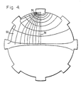
- FIG. 4 is a graphic representation of a cross-sectional pattern on a window represented by some curvilinear squares, in which each square represents equal heat dissipation, for one pair of the electrodes depicted in FIG. 1 during the time they are energized.
- Accordingly, FIG. 1 illustrates a
turret 10 which comprises a portion of an optical system, such as a FLIR (forward looking infrared system).Turret 10 includes a generallyspherical turret housing 12 which is secured to abase 14. The base is affixed, for example, to an aircraft.Turret housing 12 is adapted to rotate through substantially 360° about an axis normal tobase 14 and approximately 270° in any plane perpendicular to the plane of the base. Thus, the turret has a substantially full azimuth field of regard or view. To permit electrical connection with such pivoting, a conventionalelectrical cable 16 withcoils 16a and 16b joinshousing 12 and its electrical components to the base. To enable optical signals to be received withinhousing 12, awindow 18 is positioned generally on its periphery. For infrared viewing, the preferred material ofwindow 18 is germanium. It is throughwindow 18 that infrared radiation is received within the system. It is, therefore, desired thathousing 12 can pivot in any direction with respect tobase 14 so thatwindow 18 may be directed in almost a 360° spherical direction. - Such a
window 18 is preferrably of circular shape, as explained previously, so as to be sized as close as possible to the extent of the incoming ray or radiation bundle. Further, because of its circular configuration, such a window will exhibit non-uniform heat loss, which results in non-uniform temperature or temperature gradients within the window, when heated in a conventional manner. As contrasted to a window of rectangular design, the gradients between electrodes placed at opposite edges is uniform. In a circular window, however, the gradients do not proceed across the window uniformly but expand toward the center and then decrease as they approach the opposite electrode. Because germanium, in particular, has a high index of refraction and a high change of refractive index with a change in temperature, non-uniform heating of the window will cause severe optical distortion. Therefore, to control the nonuniformity in heating and, therefore, the temperature gradients within the window, a series ofelectrodes 20 are equally spaced about the circumference ofwindow 18. To evenly distribute the heat thereby generated, the electrodes are energized in a periodic manner by alternating the electric current thereto. Such energization includes an alternating of the electric current among the electrodes by a switching circuitry. While various alternating voltage patterns may be tailored to any specific window, it is preferred to rotate the applied voltage at a frequency that is large compared to the thermal response time of the window, thereby minimizing thermal gradients. - A typical arrangement for supplying the electric current to the electrodes is depicted in FIG. 2. The circuit arrangement is coupled to diametrically
opposed electrodes 20. While this is the preferred arrangement, it is not necessary that the connected electrodes be diametrically opposed, if the desired or thermal pattern inwindow 18 has different requirements. In the preferred arrangement, each opposed pair ofelectrodes 20 has its ownpower switching mechanism 22 connected thereto. Power is supplied tomechanism 22 from asource 24.Mechanism 22 is also coupled to acontroller 26. The controller defines whichpower switching mechanism 22 is to be closed and, therefore, which electrodepair 20 is to be energized. Included withincontroller 26 is an oscillator andtimer 28, which is coupled through a plurality of ANDGATES 30, each of which is coupled to its individualpower switching mechanism 22. Oscillator andtimer 28 define the timed sequence of closure of the power switching mechanisms as, for example, illustrated in the accompanying waveforms X1 through X4. - Also coupled to AND
GATES 30 are avoltage comparator 32 and anover-temperature control 34. The voltage comparator is coupled to athermister 36 through aconnection 38. The purpose ofvoltage comparator 32 is to set the upper and lower limits of temperature withinwindow 18.Over-temperature control 34 is coupled to anotherthermister 40 onwindow 18 through aconnection 42.Overtemperature control 34 is designed to prevent any runaway temperatures which might exist withinwindow 18 in the event thatvoltage comparator 32 does not function. Coupled also tocontroller 26 and to each of ANDGATES 30 is an opto-isolator 44 which is an isolation "on-off" switch. -
Power switching mechanism 22 is of conventional design and includes a pair of solid state relays 46 with a pair of opto-isolators 48, respectively coupled to the pairs of electrodes. - In operation, oscillator and
timer 28 provide pulses of any preset duration, herein shown by curves X1-X4, as being one quarter of the time. However, it is to be understood that any timing period may be utilized in order to obtain the desired thermal results inwindow 18. Depending upon the timing pulse from oscillator andtimer 28, the signal is sent through one of ANDGATES 30 and from thence to appropriatepower switching mechanism 22. Operation of each AND GATE is dependent upon "on-off" signals from opto-isolator 44,voltage comparator 32,over-temperature control 34 and oscillator-timer 28. If any one is not in an "on" condition, the signal from oscillator andtimer 28 will not be permitted to pass through its ANDGATE 30 to thereby causepower switching mechanism 22 to close and permit power frompower source 24 to energize theappropriate electrode pair 20. - An alternative embodiment of the FIG. 2 arrangment is depicted in FIG. 3 in which all the components are the same, with the exception of independent voltage regulators 32-1, 32-2, etc., respectively for each of AND GATES 30-1 through 30-4. Each of voltage comparators 32-1 through 32-4 are coupled to their respective thermisters 36-1 through 36-4 on the window. The purpose of having individual voltage comparators and thermisters is to provide greater flexibility in the event that it desired that any electrode pair be operated at different temperature ranges.
- Heating of a window may be understood with respect to FIG. 4 in which it is shown some of the curvilinear squares, denoted by
indicium 50, for a particular arrangement of small electrodes. This pattern is taken from an actual experiment using conductive paper to simulate the electrical conductivity of doped single crystal germanium. Two effects are discernable from the diagram. First, because each square has equal heat dissipation, it can be seen that the dissipation is highest near the energized electrodes, next highest in the center, and lowest at the sides. Secondly, shorting at the unused electrodes can also be observed. Thus, by chosing the correct number of electrodes along with their size and spacing, it is possible to achieve a more uniform heating, including the accounting for lateral conduction losses into the mount.
Claims (10)
conforming said intrinsic non-uniform temperature distribution to said desired uniform temperature distribution by periodically energizing said heating means (20).
Applications Claiming Priority (2)
| Application Number | Priority Date | Filing Date | Title |
|---|---|---|---|
| US812864 | 1985-12-23 | ||
| US06/812,864 US4829162A (en) | 1985-12-23 | 1985-12-23 | Maintenance of uniform optical window properties |
Publications (2)
| Publication Number | Publication Date |
|---|---|
| EP0252126A1 EP0252126A1 (en) | 1988-01-13 |
| EP0252126B1 true EP0252126B1 (en) | 1991-07-10 |
Family
ID=25210821
Family Applications (1)
| Application Number | Title | Priority Date | Filing Date |
|---|---|---|---|
| EP87900575A Expired EP0252126B1 (en) | 1985-12-23 | 1986-12-16 | Maintenance of uniform optical window properties |
Country Status (7)
| Country | Link |
|---|---|
| US (1) | US4829162A (en) |
| EP (1) | EP0252126B1 (en) |
| JP (1) | JP2564585B2 (en) |
| DE (1) | DE3680208D1 (en) |
| ES (1) | ES2003998A6 (en) |
| IL (1) | IL80761A (en) |
| WO (1) | WO1987004036A1 (en) |
Families Citing this family (7)
| Publication number | Priority date | Publication date | Assignee | Title |
|---|---|---|---|---|
| DE4302005C2 (en) * | 1993-01-26 | 1995-04-20 | Ver Glaswerke Gmbh | Method for heating a glass pane provided with a resistance layer |
| DE10310797B4 (en) * | 2003-03-12 | 2005-11-03 | Siemens Ag | Device for processing substrates, in particular of electrical circuit substrates, with laser |
| US8942562B2 (en) * | 2011-05-31 | 2015-01-27 | A Optix Technologies, Inc. | Integrated commercial communications network using radio frequency and free space optical data communication |
| GB2494766B (en) * | 2012-09-11 | 2014-01-01 | Selex Es Ltd | De-Icing system and method |
| US10079640B1 (en) * | 2014-07-31 | 2018-09-18 | Collinear Networks, Inc. | Window heater with reduced wavefront distortion |
| US10228527B2 (en) * | 2015-09-25 | 2019-03-12 | Raytheon Company | Gimbal transmission cable management |
| WO2022141097A1 (en) * | 2020-12-29 | 2022-07-07 | 深圳市大疆创新科技有限公司 | Electric heating infrared window of laser radar, laser radar, and movable platform |
Family Cites Families (14)
| Publication number | Priority date | Publication date | Assignee | Title |
|---|---|---|---|---|
| US2557983A (en) * | 1949-03-22 | 1951-06-26 | Pittsburgh Plate Glass Co | Transparent electroconductive article |
| US3146449A (en) * | 1961-12-29 | 1964-08-25 | Bendix Corp | Slot fed horn radiator with protective radome having polarization and resistance wires embedded therein |
| US3225173A (en) * | 1963-07-12 | 1965-12-21 | Richard T Cook | Anti-frost apparatus for optical element |
| US3553432A (en) * | 1969-06-09 | 1971-01-05 | Us Navy | Heated dome window |
| DE2227902A1 (en) * | 1972-06-08 | 1973-12-20 | Licentia Gmbh | DEVICE TO PREVENT THE CONDITIONING OF THE OPTICAL EXHAUST OPENINGS OF VIEWING EQUIPMENT |
| US3982092A (en) * | 1974-09-06 | 1976-09-21 | Libbey-Owens-Ford Company | Electrically heated zoned window systems |
| DE2443224C3 (en) * | 1974-09-10 | 1979-02-22 | Licentia Patent-Verwaltungs-Gmbh, 6000 Frankfurt | Process for deicing engine, wing and tail unit systems on missiles |
| US4039246A (en) * | 1976-01-22 | 1977-08-02 | General Dynamics Corporation | Optical scanning apparatus with two mirrors rotatable about a common axis |
| US4213029A (en) * | 1979-02-21 | 1980-07-15 | The United States Of America As Represented By The Secretary Of The Navy | Radiation transmissive housing having a heated load bearing gasket |
| DE2936398A1 (en) * | 1979-09-08 | 1981-03-26 | Ver Glaswerke Gmbh | ELECTRICALLY HEATED GLASS |
| US4346286A (en) * | 1981-02-20 | 1982-08-24 | Canargo International Pty. Ltd. | Temperature controlled electrical power supply apparatus |
| US4422725A (en) * | 1981-03-16 | 1983-12-27 | United Technologies Corporation | Method of optimally operating a graphite fiber reinforced glass matrix composite optical article |
| JPS60249282A (en) * | 1984-05-24 | 1985-12-09 | 松下電工株式会社 | Temperature control circuit |
| JPS61118818A (en) * | 1984-11-14 | 1986-06-06 | Sanyo Electric Co Ltd | Heater control method of thermostatic chamber |
-
1985
- 1985-12-23 US US06/812,864 patent/US4829162A/en not_active Expired - Lifetime
-
1986
- 1986-11-25 IL IL80761A patent/IL80761A/en not_active IP Right Cessation
- 1986-12-16 WO PCT/US1986/002759 patent/WO1987004036A1/en not_active Ceased
- 1986-12-16 JP JP62500644A patent/JP2564585B2/en not_active Expired - Lifetime
- 1986-12-16 EP EP87900575A patent/EP0252126B1/en not_active Expired
- 1986-12-16 DE DE8787900575T patent/DE3680208D1/en not_active Expired - Fee Related
- 1986-12-22 ES ES8603551A patent/ES2003998A6/en not_active Expired
Also Published As
| Publication number | Publication date |
|---|---|
| ES2003998A6 (en) | 1988-12-01 |
| US4829162A (en) | 1989-05-09 |
| JPS63502541A (en) | 1988-09-22 |
| IL80761A (en) | 1990-11-29 |
| EP0252126A1 (en) | 1988-01-13 |
| JP2564585B2 (en) | 1996-12-18 |
| WO1987004036A1 (en) | 1987-07-02 |
| DE3680208D1 (en) | 1991-08-14 |
| IL80761A0 (en) | 1987-02-27 |
Similar Documents
| Publication | Publication Date | Title |
|---|---|---|
| US5496989A (en) | Windshield temperature control system | |
| US2507036A (en) | Vehicle windshield | |
| KR100733938B1 (en) | Optical sensor cover system | |
| EP2950106B1 (en) | External case heater for an angle of attack sensor | |
| US4829162A (en) | Maintenance of uniform optical window properties | |
| EP1968854B1 (en) | Energy-efficient electro-thermal ice-protection system | |
| KR100873241B1 (en) | Cooking unit with temperature sensor assembly and radiant electric heater | |
| EP3159699B1 (en) | Architecture for air data probe power supply control | |
| JP2006524609A5 (en) | ||
| WO1993018633A1 (en) | Transparent film radiant heat source for use with incubators | |
| US3989541A (en) | Solar cell assembly | |
| US3805017A (en) | Radome anti-icing system | |
| US11874432B2 (en) | Space optical instrument comprising an improved thermal guard | |
| EP0496388A2 (en) | Carbon-fiber based device for heating antennas, preferably for use in space | |
| JP3038228B2 (en) | Star | |
| US3553432A (en) | Heated dome window | |
| US2518277A (en) | Overheat protector for heated windshields | |
| US4192989A (en) | Blanket heated photoreceptor | |
| CN109687265B (en) | Temperature control device for deliquescent crystals | |
| JPS6336602A (en) | Snow melting device for antenna | |
| RU2777542C1 (en) | Anti-icing system for satellite communication stations | |
| US3121153A (en) | Temperature regulation systems | |
| Humphrey | External automotive mirror heating with PTC materials | |
| JPH01254003A (en) | Reflector antenna | |
| RU2233018C1 (en) | Method and device for deicing ground-based parabolic antenna |
Legal Events
| Date | Code | Title | Description |
|---|---|---|---|
| PUAI | Public reference made under article 153(3) epc to a published international application that has entered the european phase |
Free format text: ORIGINAL CODE: 0009012 |
|
| 17P | Request for examination filed |
Effective date: 19870820 |
|
| AK | Designated contracting states |
Kind code of ref document: A1 Designated state(s): BE CH DE FR GB IT LI NL SE |
|
| 17Q | First examination report despatched |
Effective date: 19890222 |
|
| GRAA | (expected) grant |
Free format text: ORIGINAL CODE: 0009210 |
|
| AK | Designated contracting states |
Kind code of ref document: B1 Designated state(s): BE CH DE FR GB IT LI NL SE |
|
| REF | Corresponds to: |
Ref document number: 3680208 Country of ref document: DE Date of ref document: 19910814 |
|
| ET | Fr: translation filed | ||
| ITF | It: translation for a ep patent filed | ||
| PLBE | No opposition filed within time limit |
Free format text: ORIGINAL CODE: 0009261 |
|
| STAA | Information on the status of an ep patent application or granted ep patent |
Free format text: STATUS: NO OPPOSITION FILED WITHIN TIME LIMIT |
|
| 26N | No opposition filed | ||
| EAL | Se: european patent in force in sweden |
Ref document number: 87900575.9 |
|
| PGFP | Annual fee paid to national office [announced via postgrant information from national office to epo] |
Ref country code: FR Payment date: 19961108 Year of fee payment: 11 |
|
| PGFP | Annual fee paid to national office [announced via postgrant information from national office to epo] |
Ref country code: SE Payment date: 19961115 Year of fee payment: 11 |
|
| PGFP | Annual fee paid to national office [announced via postgrant information from national office to epo] |
Ref country code: GB Payment date: 19961121 Year of fee payment: 11 |
|
| PGFP | Annual fee paid to national office [announced via postgrant information from national office to epo] |
Ref country code: DE Payment date: 19961125 Year of fee payment: 11 |
|
| PGFP | Annual fee paid to national office [announced via postgrant information from national office to epo] |
Ref country code: NL Payment date: 19961126 Year of fee payment: 11 |
|
| PGFP | Annual fee paid to national office [announced via postgrant information from national office to epo] |
Ref country code: BE Payment date: 19961129 Year of fee payment: 11 |
|
| PGFP | Annual fee paid to national office [announced via postgrant information from national office to epo] |
Ref country code: CH Payment date: 19961203 Year of fee payment: 11 |
|
| PG25 | Lapsed in a contracting state [announced via postgrant information from national office to epo] |
Ref country code: GB Free format text: LAPSE BECAUSE OF NON-PAYMENT OF DUE FEES Effective date: 19971216 |
|
| PG25 | Lapsed in a contracting state [announced via postgrant information from national office to epo] |
Ref country code: SE Free format text: LAPSE BECAUSE OF NON-PAYMENT OF DUE FEES Effective date: 19971217 |
|
| PG25 | Lapsed in a contracting state [announced via postgrant information from national office to epo] |
Ref country code: LI Free format text: LAPSE BECAUSE OF NON-PAYMENT OF DUE FEES Effective date: 19971231 Ref country code: FR Free format text: THE PATENT HAS BEEN ANNULLED BY A DECISION OF A NATIONAL AUTHORITY Effective date: 19971231 Ref country code: CH Free format text: LAPSE BECAUSE OF NON-PAYMENT OF DUE FEES Effective date: 19971231 Ref country code: BE Free format text: LAPSE BECAUSE OF NON-PAYMENT OF DUE FEES Effective date: 19971231 |
|
| BERE | Be: lapsed |
Owner name: HUGHES AIRCRAFT CY Effective date: 19971231 |
|
| PG25 | Lapsed in a contracting state [announced via postgrant information from national office to epo] |
Ref country code: NL Free format text: LAPSE BECAUSE OF NON-PAYMENT OF DUE FEES Effective date: 19980701 |
|
| GBPC | Gb: european patent ceased through non-payment of renewal fee |
Effective date: 19971216 |
|
| REG | Reference to a national code |
Ref country code: CH Ref legal event code: PL |
|
| NLV4 | Nl: lapsed or anulled due to non-payment of the annual fee |
Effective date: 19980701 |
|
| PG25 | Lapsed in a contracting state [announced via postgrant information from national office to epo] |
Ref country code: DE Free format text: LAPSE BECAUSE OF NON-PAYMENT OF DUE FEES Effective date: 19980901 |
|
| EUG | Se: european patent has lapsed |
Ref document number: 87900575.9 |
|
| REG | Reference to a national code |
Ref country code: FR Ref legal event code: ST |
|
| PG25 | Lapsed in a contracting state [announced via postgrant information from national office to epo] |
Ref country code: IT Free format text: LAPSE BECAUSE OF NON-PAYMENT OF DUE FEES;WARNING: LAPSES OF ITALIAN PATENTS WITH EFFECTIVE DATE BEFORE 2007 MAY HAVE OCCURRED AT ANY TIME BEFORE 2007. THE CORRECT EFFECTIVE DATE MAY BE DIFFERENT FROM THE ONE RECORDED. Effective date: 20051216 |