EP0251198A2 - Apparatus for diagnosing abnormal state of sodium (Na) - sulfur (S) cell - Google Patents
Apparatus for diagnosing abnormal state of sodium (Na) - sulfur (S) cell Download PDFInfo
- Publication number
- EP0251198A2 EP0251198A2 EP87109118A EP87109118A EP0251198A2 EP 0251198 A2 EP0251198 A2 EP 0251198A2 EP 87109118 A EP87109118 A EP 87109118A EP 87109118 A EP87109118 A EP 87109118A EP 0251198 A2 EP0251198 A2 EP 0251198A2
- Authority
- EP
- European Patent Office
- Prior art keywords
- cell
- sodium
- sulfur
- ripple
- discharging
- Prior art date
- Legal status (The legal status is an assumption and is not a legal conclusion. Google has not performed a legal analysis and makes no representation as to the accuracy of the status listed.)
- Granted
Links
Images


Classifications
-
- H—ELECTRICITY
- H01—ELECTRIC ELEMENTS
- H01M—PROCESSES OR MEANS, e.g. BATTERIES, FOR THE DIRECT CONVERSION OF CHEMICAL ENERGY INTO ELECTRICAL ENERGY
- H01M10/00—Secondary cells; Manufacture thereof
- H01M10/42—Methods or arrangements for servicing or maintenance of secondary cells or secondary half-cells
- H01M10/48—Accumulators combined with arrangements for measuring, testing or indicating the condition of cells, e.g. the level or density of the electrolyte
-
- G—PHYSICS
- G01—MEASURING; TESTING
- G01R—MEASURING ELECTRIC VARIABLES; MEASURING MAGNETIC VARIABLES
- G01R31/00—Arrangements for testing electric properties; Arrangements for locating electric faults; Arrangements for electrical testing characterised by what is being tested not provided for elsewhere
- G01R31/36—Arrangements for testing, measuring or monitoring the electrical condition of accumulators or electric batteries, e.g. capacity or state of charge [SoC]
- G01R31/378—Arrangements for testing, measuring or monitoring the electrical condition of accumulators or electric batteries, e.g. capacity or state of charge [SoC] specially adapted for the type of battery or accumulator
-
- Y—GENERAL TAGGING OF NEW TECHNOLOGICAL DEVELOPMENTS; GENERAL TAGGING OF CROSS-SECTIONAL TECHNOLOGIES SPANNING OVER SEVERAL SECTIONS OF THE IPC; TECHNICAL SUBJECTS COVERED BY FORMER USPC CROSS-REFERENCE ART COLLECTIONS [XRACs] AND DIGESTS
- Y02—TECHNOLOGIES OR APPLICATIONS FOR MITIGATION OR ADAPTATION AGAINST CLIMATE CHANGE
- Y02E—REDUCTION OF GREENHOUSE GAS [GHG] EMISSIONS, RELATED TO ENERGY GENERATION, TRANSMISSION OR DISTRIBUTION
- Y02E60/00—Enabling technologies; Technologies with a potential or indirect contribution to GHG emissions mitigation
- Y02E60/10—Energy storage using batteries
Definitions
- This invention relates to a method and apparatus for diagnosing a sodium-sulfur cell for the presence or absence of any abnormal state, and more particularly to a method and apparatus of the kind described above which can detect progress of degradation of a sodium-sulfur cell and predict possibility of catastrophic breakdown of the cell in a very near future before such a final breakdown of the cell actually occurs.
- a sodium-sulfur cell (which will be often abbreviated hereinafter as an Na-S cell) is a secondary cell of a type operating at a high temperature.
- molten sodium which is a reactant of a negative electrode is disposed on one side of an electrolyte tube permeable to sodium ions only, while molten sulfur which is a reactant of a positive electrode is disposed on the other side of the electrolyte tube.
- the sodium-sulfur cell is charged and discharged at a temperature as high as about 300 to 350°C. The following cell reaction occurs when the sodium-sulfur cell is charged and discharged:
- sodium turns into sodium ions by freeing electrons, and the sodium ions permeate the electrolyte tube, which is the separator, and react with sulfur to produce sodium polysulfide, Na2Sx, as a discharged product.
- a voltage higher than the cell voltage is applied across the cell to cause a reaction reverse to that occurring in the discharge mode.
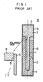
- Fig. l shows a practical structure of a prior art sodium-sulfur cell 9.
- a bladder-like electrolyte tube l made of a material such as ⁇ -alumina having an Na-ion conductivity is coaxially disposed in a positive electrode container (an outer electrode) 2 in the form of a cylindrical metal member having a closed bottom, in such a relation that a predetermined spacing a is maintained between the electrolyte tube l and the positive electrode container 2.
- the electrolyte tube l is joined or fixed at the outer periphery of its upper end opening 3 to a member 4 of an electrical insulator such as ⁇ -alumina ring in a cantilever fashion by a jointing member 5 such as glass solder.
- a negative electrode container 6 in the form of a cylindrical member having a closed top is disposed opposite to and fixed to the positive electrode container 2 through the insulator member 4 to constitute the cell body.
- porous carbon impregnated with sulfur acting as a positive reactant is filled to constitute a positive electrode 8.
- the metal fibers filled in the space b to constitute the negative electrode 7 together with the sodium have a function of holding the sodium so as to prevent occurrence of a violent exothermic reaction between the sodium and the sulfur which direct reaction occurs when the electrolyte tube l is ruptured.
- the carbon filled in the space c to constitute the positive electrode 8 acts to give an electron conductivity to the sulfur. That is, a graphite (carbon) mat is impregnated with sulfur.
- the wall thickness of the partitioning electrolyte tube l permeable to sodium ions is advantageously as small as possible.
- JP-A-47-2843l Japanese Patent Laid-Open in l972
- Japanese Patent Laid-Open in l972 Japanese Patent Laid-Open in l972
- this known publication does not disclose any especial technique for diagnosing an abnormal state of the Na/S cell. That is, the known publication merely discloses the structure of an Na/S cell in which a conductive composite having a porosity of 50 to 98% and a pore diameter of l0 to l,000 ⁇ is used to constitute its positive electrode.
- a further object of the present invention is to provide a cell diagnosing method which can simply predict the presence of an abnormal state in any one of Na/S cells constituting each of modules which are minimum controlled units of a power storage system, so that a module including a faulty Na/S cell can be bodily replaced by a sound one.
- a further another object of the present invention is to automatically stop the charge-discharge operation of the Na/S cell when the Na/S cell is detected abnormal.
- the inventors made researches and studies on symptons exhibited by an Na/S cell with progressive degradation of the cell toward the time of final breakdown, and measured and analyzed all of data which could be externally observed. As a result of the measurement and analysis, the inventors have discovered that, when the Na/S cell is charged and discharged, minute fluctuation is observed in the operating voltage of the cell.
- the inventors have ascertained that the voltage fluctuation described above (that is, a voltage ripple) occurs immediately before the Na/S cell having been progressively degraded is finally damaged.
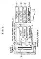
- Fig. 2 is a systematic diagram of a voltage ripple measuring apparatus which is a basic form of the present invention
- Fig. 3 shows voltage ripples recorded by the x-t recorder shown in Fig. 2 to illustrate a tendency of occurrence of the voltage ripples
- Fig. 4 shows the voltage ripple waveforms displayed on an electromagnetic oscillograph.
- an Na/S cell 9 is of a type operable at a high temperature of 300 to 350°C and is placed in an electric furnace l0 where the cell 9 is heated by an electric heater ll to be maintained at the operating temperature.
- the Na/S cell 9 is charged and discharged at an interval of a predetermined period of time by a charge-discharge apparatus (not shown) automatically repeating charging operation and discharging operation.
- the voltage, current and temperature of the Na/S cell 9 are detected by a voltage measuring terminal l3 of a cycler l2 (a charging and discharging device), an electric power supply cable l4 and a temperature sensor l5 respectively and recorded by a recorder l6.
- the operating voltage of the Na/S cell 9 is directly read by a voltmeter l7.
- a d.c. amplifier l8 acts to drift a d.c. component of the operating voltage of the Na/S cell 9 and, at the same time, amplifies a ripple component of the operating voltage of the Na/S cell 9.
- the output of the d.c. amplifier l8 is applied to a low-pass filter l9 which removes a power-source noise component from the input, and the ripple component only of the operating voltage of the Na/S cell 9 is recorded by an electromagnetic oscillograph 20.
- the output voltage of the Na/S cell 9 is passed through a capacitor C which acts to remove the d.c. component therefrom, and the output of the capacitor C is applied to an x-t recorder 2l which records a tendency of appearance of voltage ripples during charging and discharging the Na/S cell 9.
- Fig. 3 shows voltage fluctuations recorded by the x-t recorder 2l
- Fig. 4 shows the fluctuating voltage waveforms recorded by the electromagnetic oscillograph 20.
- Fig. 5 shows an electric power storage system using Na/S cells.
- a plurality of Na/S cells 9 are connected in parallel to each other to constitute a submodule 22.
- a plurality of such submodules 22 are connected in series with each other, and a thermo-couple 23, a heater 24 and a heat insulating member 25 are combined with the submodules 22 to constitute a module 26.
- a plurality of such modules 26 are connected in series with each other to constitute a unit 27 of an electric power storage system.
- thermo-couple 23 installed in each module 26 can be maintained constant
- the heater 24 is on-off controlled, and the rotation speed of a blower 28 is also controlled. According to circumstances, the current of a DC/AC inverter 29 is controlled.
- the Na/S cells 9 in the modules 26 constituting the unit 27 of the electric power storage system are charged with direct current and discharged with direct current.
- the d.c. output voltage of the unit 27 is converted by the Dc/Ac inverter 29 into an a.c. voltage, and this a.c. voltage is supplied to an electric power system after being boosted by a transformer 30.
- a volt-meter 3l is connected across each of the modules 26 which are smallest units to be controlled, and a minute fluctuation of the operating voltage during charging and discharging the module 26 is observed. By observing such a minute voltage fluctuation, breakdown of any one of the Na/S cells 9 constituting the module 26 and a symptom of the cell breakdown can be easily predicted.
- a ripple component having a level exceeding a predetermined pulse peak value is detected by a pulse detector 32 from the output of the volt-meter 3l, and the frequency of appearance of such ripple components or pulses within a predetermined period of time is counted.
- the module 26 including the damaged Na/S cell 9 can be repaired or replaced before breakdown of many Na/S cells 9 occurs, so that the reliability of the entire power storage system using the Na/S cells can be improved.
- the presence or absence of a damaged Na/S cell in each of modules which are smallest controlled units of an electric power storage system can be simply predicted, so that the module including the damaged Na/S cell can only be replaced without requiring expensive detecting means.
- the operation for charging or discharging the Na/S cells can be automatically stopped when a damaged Na/S cell is detected.
Landscapes
- Engineering & Computer Science (AREA)
- Manufacturing & Machinery (AREA)
- Chemical & Material Sciences (AREA)
- Chemical Kinetics & Catalysis (AREA)
- Electrochemistry (AREA)
- General Chemical & Material Sciences (AREA)
- Physics & Mathematics (AREA)
- General Physics & Mathematics (AREA)
- Secondary Cells (AREA)
Abstract
Description
- This invention relates to a method and apparatus for diagnosing a sodium-sulfur cell for the presence or absence of any abnormal state, and more particularly to a method and apparatus of the kind described above which can detect progress of degradation of a sodium-sulfur cell and predict possibility of catastrophic breakdown of the cell in a very near future before such a final breakdown of the cell actually occurs.
- A sodium-sulfur cell (which will be often abbreviated hereinafter as an Na-S cell) is a secondary cell of a type operating at a high temperature. In the sodium-sulfur cell, molten sodium which is a reactant of a negative electrode is disposed on one side of an electrolyte tube permeable to sodium ions only, while molten sulfur which is a reactant of a positive electrode is disposed on the other side of the electrolyte tube. The sodium-sulfur cell is charged and discharged at a temperature as high as about 300 to 350°C. The following cell reaction occurs when the sodium-sulfur cell is charged and discharged:

- That is, in the discharge mode, sodium turns into sodium ions by freeing electrons, and the sodium ions permeate the electrolyte tube, which is the separator, and react with sulfur to produce sodium polysulfide, Na₂Sx, as a discharged product. On the other hand, in the charge mode, a voltage higher than the cell voltage is applied across the cell to cause a reaction reverse to that occurring in the discharge mode.
- Fig. l shows a practical structure of a prior art sodium-
sulfur cell 9. - Referring to Fig. l, a bladder-like electrolyte tube l made of a material such as β-alumina having an Na-ion conductivity is coaxially disposed in a positive electrode container (an outer electrode) 2 in the form of a cylindrical metal member having a closed bottom, in such a relation that a predetermined spacing a is maintained between the electrolyte tube l and the
positive electrode container 2. The electrolyte tube l is joined or fixed at the outer periphery of its upper end opening 3 to amember 4 of an electrical insulator such as α-alumina ring in a cantilever fashion by a jointingmember 5 such as glass solder. Anegative electrode container 6 in the form of a cylindrical member having a closed top is disposed opposite to and fixed to thepositive electrode container 2 through theinsulator member 4 to constitute the cell body. - In the space b enclosed by the electrolyte tube l and
negative electrode container 6, sodium acting as a negative reactant is filled together with porous metal fibers to constitute anegative electrode 7. - On the other hand, in the space c enclosed by the electrolyte tube l and
positive electrode container 2, porous carbon impregnated with sulfur acting as a positive reactant is filled to constitute a positive electrode 8. The metal fibers filled in the space b to constitute thenegative electrode 7 together with the sodium have a function of holding the sodium so as to prevent occurrence of a violent exothermic reaction between the sodium and the sulfur which direct reaction occurs when the electrolyte tube l is ruptured. Further, the carbon filled in the space c to constitute the positive electrode 8 acts to give an electron conductivity to the sulfur. That is, a graphite (carbon) mat is impregnated with sulfur. - In order that the cell reaction can easily take place in the Na/S cell constructed in the manner described above, the wall thickness of the partitioning electrolyte tube l permeable to sodium ions is advantageously as small as possible.
- However, minute cracks tend to occur in the electrolyte tube l as the Na/S cell is repeatedly charged and discharged, and the cracks will develop to such an extent that the electrolyte tube l is finally ruptured. In such an event, the sodium directly reacts with the sulfur thereby destroying the function of the cell.
- Primarily, many sodium-sulfur cells are connected for the purpose of storage of electric power. Accordingly, impossibility of electric power supply or storage due to breakdown of any one of such sodium-sulfur cells greatly adversely affects the social life as a result of, for example, a sudden stoppage of electric power supply.
- JP-A-47-2843l (Japanese Patent Laid-Open in l972) is a newest publication relating to an Na/S cell. However, this known publication does not disclose any especial technique for diagnosing an abnormal state of the Na/S cell. That is, the known publication merely discloses the structure of an Na/S cell in which a conductive composite having a porosity of 50 to 98% and a pore diameter of l0 to l,000 µ is used to constitute its positive electrode.
- In view of the circumstances described above, it is a main object of the present invention to provide a method of diagnosing the Na/S cell so that an abnormal state attributable to occurrence of minute cracks in an electrolyte tube due to progressive degradation of the cell as a result of repeated cycles of charging and discharging can be predicted and discovered before the cracks penetrate the electrolyte tube resulting finally in destruction of the Na/S cell.
- A further object of the present invention is to provide a cell diagnosing method which can simply predict the presence of an abnormal state in any one of Na/S cells constituting each of modules which are minimum controlled units of a power storage system, so that a module including a faulty Na/S cell can be bodily replaced by a sound one.
- A further another object of the present invention is to automatically stop the charge-discharge operation of the Na/S cell when the Na/S cell is detected abnormal.
- In accordance with the present invention which attains the objects described above, there are provided method and apparatus for diagnosing the presence or absence of an abnormal state in the sodium-sulfur cell containing a porous electrical conductive material impregnated with molten sulfur or sodium polysulfide as its positive electrode and containing sodium as its negative electrode, wherein the operating voltage of the sodium-sulfur cell during charging and discharging is observed to detect occurrence of a ripple in the operating voltage, and, when the amplitude of the ripple and the frequency of occurrence of the ripple increases as a result of cycles of repeated charging and discharging, the Na/S cell is decided that its degradation has progressed to the extent that catastrophic breakdown of the cell will occur in a very near future.
- By so observing and deciding, breakdown of the Na/S cell can be predicted before the Na/S cell is finally damaged (for example, at time earlier by several charge-discharge cycles than the time of actual breakdown). Therefore, an appropriate countermeasure of stopping the operation of the damaged Na/S cell and repairing or replacing the cell can be taken before actual breakdown occurs.
- Preferred embodiments of the present invention will now be described in conjunction with the accompanying drawings, in which:
- Fig. l shows a practical structure of a prior art Na/S cell;
- Fig. 2 is a block diagram of a voltage ripple measuring apparatus which is a basic form of the present invention;
- Fig. 3 shows voltage ripples recorded by the x-t recorder in the measuring apparatus shown in Fig. 2;
- Fig. 4 shows voltage ripple waveforms displayed on an electromagentic osc illograph; and
- Fig. 5 is a systematic view of an electric power storage system using Na/S cells, to which the present invention is applied.
- Before describing preferred embodiments of the present invention, the basic principle of the present invention will be briefly described.
- The inventors made researches and studies on symptons exhibited by an Na/S cell with progressive degradation of the cell toward the time of final breakdown, and measured and analyzed all of data which could be externally observed. As a result of the measurement and analysis, the inventors have discovered that, when the Na/S cell is charged and discharged, minute fluctuation is observed in the operating voltage of the cell.
- As a result of the analysis of vast data over a long period of time, the inventors have ascertained that the voltage fluctuation described above (that is, a voltage ripple) occurs immediately before the Na/S cell having been progressively degraded is finally damaged.
- Since this voltage fluctuation is considered to be related to deterioration and rupture of the electrolyte tube l, the inventors have measured in detail the phenomena of voltage fluctuation under various operating conditions of the cell and investigated the features of the voltage fluctuation.
- Fig. 2 is a systematic diagram of a voltage ripple measuring apparatus which is a basic form of the present invention, Fig. 3 shows voltage ripples recorded by the x-t recorder shown in Fig. 2 to illustrate a tendency of occurrence of the voltage ripples, and Fig. 4 shows the voltage ripple waveforms displayed on an electromagnetic oscillograph.
- Referring to Fig. 2, an Na/
S cell 9 is of a type operable at a high temperature of 300 to 350°C and is placed in an electric furnace l0 where thecell 9 is heated by an electric heater ll to be maintained at the operating temperature. - The Na/
S cell 9 is charged and discharged at an interval of a predetermined period of time by a charge-discharge apparatus (not shown) automatically repeating charging operation and discharging operation. The voltage, current and temperature of the Na/S cell 9 are detected by a voltage measuring terminal l3 of a cycler l2 (a charging and discharging device), an electric power supply cable l4 and a temperature sensor l5 respectively and recorded by a recorder l6. - Besides this recorder l6, the operating voltage of the Na/
S cell 9 is directly read by a voltmeter l7. Further, a d.c. amplifier l8 acts to drift a d.c. component of the operating voltage of the Na/S cell 9 and, at the same time, amplifies a ripple component of the operating voltage of the Na/S cell 9. The output of the d.c. amplifier l8 is applied to a low-pass filter l9 which removes a power-source noise component from the input, and the ripple component only of the operating voltage of the Na/S cell 9 is recorded by anelectromagnetic oscillograph 20. - At the same time, the output voltage of the Na/
S cell 9 is passed through a capacitor C which acts to remove the d.c. component therefrom, and the output of the capacitor C is applied to an x-t recorder 2l which records a tendency of appearance of voltage ripples during charging and discharging the Na/S cell 9. - Fig. 3 shows voltage fluctuations recorded by the x-t recorder 2l, and Fig. 4 shows the fluctuating voltage waveforms recorded by the
electromagnetic oscillograph 20. - From Figs. 3 and 4, the following facts have been found:
- l) A minute fluctuation of the operating voltage starts to be observed from the time earlier by several cycles than the time of final breakdown of the Na/
S cell 9. The amplitude of the fluctuations and the frequency of occurrence of the fluctuations increase progressively towards the time of final breakdown of the Na/S cell 9. - 2) The tendency of occurrence of the voltage f luctuations during charging the
cell 9 is more marked than that during discharging thecell 9. Further, the voltage fluctuation is not almost observed in the open-circuit condition between the charging operation and the discharging operation immediately before the final breakdown of thecell 9 takes place. - 3) The voltage fluctuation has a pulse waveform, and the pulse width of a typical waveform is about 50 msec.
- 4) After the final breakdown of the
cell 9, a voltage variation considered to be attributable to cracking of the electrolyte tube l occurs even in the open-circuit condition. Further, although not shown, a greater voltage variation occurs at a temperature in the vicinity of the freezing point of the reactant as the temperature goes down after the final breakdown of thecell 9. - Although the mechanism of occurrence of such a voltage variation is not clear at the present time, the inventors consider that this mechanism has some relation with the progress of formation of minute cracks in the electrolyte tube l.
- Thus, by measuring these phenomena, the time of final breakdown of the sodium-sulfur cell can be easily and accurately predicted.
- An embodiment of the present invention will now be described with reference to Fig. 5 which shows an electric power storage system using Na/S cells.
- Referring to Fig. 5, a plurality of Na/
S cells 9 are connected in parallel to each other to constitute asubmodule 22. A plurality ofsuch submodules 22 are connected in series with each other, and a thermo-couple 23, aheater 24 and aheat insulating member 25 are combined with thesubmodules 22 to constitute amodule 26. A plurality ofsuch modules 26 are connected in series with each other to constitute aunit 27 of an electric power storage system. - In order that the temperature measured by the thermo-
couple 23 installed in eachmodule 26 can be maintained constant, theheater 24 is on-off controlled, and the rotation speed of ablower 28 is also controlled. According to circumstances, the current of a DC/AC inverter 29 is controlled. - The Na/
S cells 9 in themodules 26 constituting theunit 27 of the electric power storage system are charged with direct current and discharged with direct current. The d.c. output voltage of theunit 27 is converted by the Dc/Ac inverter 29 into an a.c. voltage, and this a.c. voltage is supplied to an electric power system after being boosted by atransformer 30. - A volt-meter 3l is connected across each of the
modules 26 which are smallest units to be controlled, and a minute fluctuation of the operating voltage during charging and discharging themodule 26 is observed. By observing such a minute voltage fluctuation, breakdown of any one of the Na/S cells 9 constituting themodule 26 and a symptom of the cell breakdown can be easily predicted. - For the purpose of concretely detecting the symptom of the breakdown of any one of the Na/
S cells 9 on the basis of the observed minute fluctuation of the cell operating voltage, a ripple component having a level exceeding a predetermined pulse peak value is detected by apulse detector 32 from the output of the volt-meter 3l, and the frequency of appearance of such ripple components or pulses within a predetermined period of time is counted. - When the frequency of appearance of such pulses exceeds a limit, the presence of a damaged Na/
S cell 9 is informed by analarm generator 33 connected to thepulse detector 32, and a switch 34 is opened to step charging or discharging the Na/S cells 9. - By taking an appropriate measure as described above, the
module 26 including the damaged Na/S cell 9 can be repaired or replaced before breakdown of many Na/S cells 9 occurs, so that the reliability of the entire power storage system using the Na/S cells can be improved. - According to the method and apparatus of the present invention described in det ail above, breakdown of an Na/S cell which has been degraded due to repeated charging and discharging can be predicted before its final breakdown occurs. Because of the practical effect described above, the present invention contributes greatly to improvements in the reliability of an electric power storage system using Na/S cells.
- Further, according to the method and apparatus of the present invention, the presence or absence of a damaged Na/S cell in each of modules which are smallest controlled units of an electric power storage system can be simply predicted, so that the module including the damaged Na/S cell can only be replaced without requiring expensive detecting means.
- Furthermore, according to the method and apparatus of the present invention, the operation for charging or discharging the Na/S cells can be automatically stopped when a damaged Na/S cell is detected.
Claims (3)
a plurality of modules (26), each said module (26) being constituted by connecting a plurality of submodules (22) in series with each other, each said submodule (22) being constituted by connecting a plurality of said sodium-sulfur celles (9) in parallel with each other;
a volt-meter (31) connected across each of said modules (26);
a pulse detector (32) connected to said volt-meters (31) connected to said modules (26) respectively, for detecting a voltage ripple having a level exceeding a predetermined pulse peak value from an output of each of said voltmeters (31);
an alarm generator (33) connected to said pulse detector (32) for generating an alarm when said ripple is detected; and
a switch (34) connected to said pulse detector (32) and opened to stop charging and discharging said sodium-sulfur cells (9) when said ripple is detected.
Applications Claiming Priority (2)
| Application Number | Priority Date | Filing Date | Title |
|---|---|---|---|
| JP147069/86 | 1986-06-25 | ||
| JP61147069A JPS634570A (en) | 1986-06-25 | 1986-06-25 | Diagnosis of abnormality for sodium-sulfur battery |
Publications (3)
| Publication Number | Publication Date |
|---|---|
| EP0251198A2 true EP0251198A2 (en) | 1988-01-07 |
| EP0251198A3 EP0251198A3 (en) | 1988-03-30 |
| EP0251198B1 EP0251198B1 (en) | 1993-04-14 |
Family
ID=15421774
Family Applications (1)
| Application Number | Title | Priority Date | Filing Date |
|---|---|---|---|
| EP87109118A Expired - Lifetime EP0251198B1 (en) | 1986-06-25 | 1987-06-25 | Apparatus for diagnosing abnormal state of sodium (na) - sulfur (s) cell |
Country Status (4)
| Country | Link |
|---|---|
| US (1) | US4881026A (en) |
| EP (1) | EP0251198B1 (en) |
| JP (1) | JPS634570A (en) |
| DE (1) | DE3785392T2 (en) |
Cited By (1)
| Publication number | Priority date | Publication date | Assignee | Title |
|---|---|---|---|---|
| EP0609101A1 (en) * | 1993-01-29 | 1994-08-03 | Canon Kabushiki Kaisha | Electric power accumulating apparatus and electric power system |
Families Citing this family (9)
| Publication number | Priority date | Publication date | Assignee | Title |
|---|---|---|---|---|
| WO1998042039A1 (en) * | 1997-03-17 | 1998-09-24 | Hitachi, Ltd. | Sodium-sulfur cell |
| JPH1118322A (en) * | 1997-06-24 | 1999-01-22 | Okamura Kenkyusho:Kk | Parallel monitor with turn-on function |
| JP3505124B2 (en) * | 2000-03-28 | 2004-03-08 | 東京電力株式会社 | Emergency power supply system and system for automatically detecting the presence or absence of failure of a single cell in a battery used in the system |
| US7778736B2 (en) * | 2000-06-14 | 2010-08-17 | Marvell International Ltd. | Apparatus, method, and computer program for sprinkler control |
| KR100385357B1 (en) * | 2001-06-01 | 2003-05-27 | 삼성에스디아이 주식회사 | Lithium-sulfur battery |
| JP5486822B2 (en) * | 2009-02-17 | 2014-05-07 | 株式会社日立製作所 | Battery system |
| US10375901B2 (en) | 2014-12-09 | 2019-08-13 | Mtd Products Inc | Blower/vacuum |
| US12259776B2 (en) * | 2019-04-24 | 2025-03-25 | Gs Yuasa International Ltd. | Maintenance method for energy storage system and computer program |
| CN114019383B (en) * | 2021-09-24 | 2024-03-29 | 浙江安力能源有限公司 | Screening method of sodium-nickel battery monomer |
Family Cites Families (9)
| Publication number | Priority date | Publication date | Assignee | Title |
|---|---|---|---|---|
| US3519842A (en) * | 1964-12-17 | 1970-07-07 | Matsushita Electric Industrial Co Ltd | Voltage switching device |
| US3661748A (en) * | 1970-04-07 | 1972-05-09 | Instrumentation Labor Inc | Fault sensing instrumentation |
| FR2137038B1 (en) * | 1971-05-12 | 1974-03-22 | Comp Generale Electricite | |
| US4274043A (en) * | 1978-12-21 | 1981-06-16 | The Dow Chemical Company | Efficient, high power battery module; D.C. transformers and multi-terminal D.C. power networks utilizing same |
| US4368423A (en) * | 1981-01-13 | 1983-01-11 | Liburdy Robert P | Apparatus for determining cell membrane dielectric breakdown |
| JPS5897273A (en) * | 1981-12-02 | 1983-06-09 | Yuasa Battery Co Ltd | Combination battery device |
| JPS58153183A (en) * | 1982-03-08 | 1983-09-12 | Central Res Inst Of Electric Power Ind | Forecasting of dielectric breakdown due to deterioration in electric tree |
| FR2537785A1 (en) * | 1982-12-13 | 1984-06-15 | Electricite De France | DEVICE FOR CONTROLLING THE CAPACITY OF A BATTERY OF ACCUMULATOR ELEMENTS |
| JPS59151777A (en) * | 1983-02-18 | 1984-08-30 | Hitachi Ltd | Sodium-sulfur battery system |
-
1986
- 1986-06-25 JP JP61147069A patent/JPS634570A/en active Granted
-
1987
- 1987-06-25 US US07/066,208 patent/US4881026A/en not_active Expired - Lifetime
- 1987-06-25 EP EP87109118A patent/EP0251198B1/en not_active Expired - Lifetime
- 1987-06-25 DE DE87109118T patent/DE3785392T2/en not_active Expired - Fee Related
Cited By (2)
| Publication number | Priority date | Publication date | Assignee | Title |
|---|---|---|---|---|
| EP0609101A1 (en) * | 1993-01-29 | 1994-08-03 | Canon Kabushiki Kaisha | Electric power accumulating apparatus and electric power system |
| US5744936A (en) * | 1993-01-29 | 1998-04-28 | Canon Kabushiki Kaisha | Electric power accumulating apparatus and electric power system |
Also Published As
| Publication number | Publication date |
|---|---|
| JPS634570A (en) | 1988-01-09 |
| EP0251198A3 (en) | 1988-03-30 |
| DE3785392D1 (en) | 1993-05-19 |
| EP0251198B1 (en) | 1993-04-14 |
| JPH0472358B2 (en) | 1992-11-18 |
| US4881026A (en) | 1989-11-14 |
| DE3785392T2 (en) | 1993-09-30 |
Similar Documents
| Publication | Publication Date | Title |
|---|---|---|
| EP0276305B1 (en) | Apparatus and method for measuring battery condition | |
| Schmitt et al. | Measurement of gas pressure inside large-format prismatic lithium-ion cells during operation and cycle aging | |
| EP0251198B1 (en) | Apparatus for diagnosing abnormal state of sodium (na) - sulfur (s) cell | |
| EP3186651B1 (en) | Electrochemical impedance spectroscopy in battery management systems | |
| JP6114321B2 (en) | Reuse method of secondary battery for vehicle | |
| DE69005672T2 (en) | Monitoring a battery. | |
| KR101119314B1 (en) | Device and method for measuring individual cell voltages in a cell stack of an energy accumulator | |
| WO2017024411A1 (en) | Methods and systems for determining battery charge or formation completeness | |
| EP0595466A1 (en) | Capacity indicator for lead-acid batteries | |
| AU2010235916B2 (en) | Electrode configuration for LiMCA | |
| JPH076795A (en) | Battery internal condition detector | |
| KR20040090420A (en) | Device and method for monitoring an electrical battery in a submarine | |
| CA2344386A1 (en) | Apparatus and method for determining the capacity of a nickel-cadmium battery | |
| EP0807826A2 (en) | Pilot cell for a battery | |
| KR20060107473A (en) | Battery management device with impedance measurement and individual automatic charge and discharge functions | |
| RU2730535C1 (en) | Electrical insulation quality monitoring device | |
| JP2658502B2 (en) | Lead-acid battery internal impedance measurement device | |
| EP4435453A1 (en) | Apparatus for identifying the parameters of a substitute electrical scheme of accumulators and the method for identifying | |
| JPH07169473A (en) | Fuel cell and external diagnosis method thereof | |
| SU864152A1 (en) | Pear detector | |
| SU959189A1 (en) | Method of monitoring the state of chemical power source | |
| Moongkumglang et al. | EIS-Based Technique for SOH Estimation of Lithium-Ion Batteries | |
| JP4705207B2 (en) | Storage battery status monitoring method | |
| Nebl | Electrical characterisation of lithium-ion cells above their operating range | |
| RU1779748C (en) | Device for monitoring strained state of rock mass |
Legal Events
| Date | Code | Title | Description |
|---|---|---|---|
| PUAI | Public reference made under article 153(3) epc to a published international application that has entered the european phase |
Free format text: ORIGINAL CODE: 0009012 |
|
| AK | Designated contracting states |
Kind code of ref document: A2 Designated state(s): DE GB |
|
| PUAL | Search report despatched |
Free format text: ORIGINAL CODE: 0009013 |
|
| RIN1 | Information on inventor provided before grant (corrected) |
Inventor name: TAKAHASHI, EIJI Inventor name: MORI, SADAO Inventor name: MIYATAKE, YOSHITERU Inventor name: HATOH, HISAMITU Inventor name: WADA, MOTOI NOBAKANEICHI ICHIJO 301 Inventor name: KAWAMOTO, HIROYUKI Inventor name: ISHIDA, YASUMASA |
|
| AK | Designated contracting states |
Kind code of ref document: A3 Designated state(s): DE GB |
|
| 17P | Request for examination filed |
Effective date: 19880405 |
|
| 17Q | First examination report despatched |
Effective date: 19901221 |
|
| GRAA | (expected) grant |
Free format text: ORIGINAL CODE: 0009210 |
|
| AK | Designated contracting states |
Kind code of ref document: B1 Designated state(s): DE GB |
|
| REF | Corresponds to: |
Ref document number: 3785392 Country of ref document: DE Date of ref document: 19930519 |
|
| PLBE | No opposition filed within time limit |
Free format text: ORIGINAL CODE: 0009261 |
|
| STAA | Information on the status of an ep patent application or granted ep patent |
Free format text: STATUS: NO OPPOSITION FILED WITHIN TIME LIMIT |
|
| 26N | No opposition filed | ||
| REG | Reference to a national code |
Ref country code: GB Ref legal event code: IF02 |
|
| PGFP | Annual fee paid to national office [announced via postgrant information from national office to epo] |
Ref country code: GB Payment date: 20020613 Year of fee payment: 16 |
|
| PGFP | Annual fee paid to national office [announced via postgrant information from national office to epo] |
Ref country code: DE Payment date: 20020829 Year of fee payment: 16 |
|
| PG25 | Lapsed in a contracting state [announced via postgrant information from national office to epo] |
Ref country code: GB Free format text: LAPSE BECAUSE OF NON-PAYMENT OF DUE FEES Effective date: 20030625 |
|
| PG25 | Lapsed in a contracting state [announced via postgrant information from national office to epo] |
Ref country code: DE Free format text: LAPSE BECAUSE OF NON-PAYMENT OF DUE FEES Effective date: 20040101 |
|
| GBPC | Gb: european patent ceased through non-payment of renewal fee |
Effective date: 20030625 |