EP0250618B1 - Shovel dipper bail assembly - Google Patents
Shovel dipper bail assembly Download PDFInfo
- Publication number
- EP0250618B1 EP0250618B1 EP19860108661 EP86108661A EP0250618B1 EP 0250618 B1 EP0250618 B1 EP 0250618B1 EP 19860108661 EP19860108661 EP 19860108661 EP 86108661 A EP86108661 A EP 86108661A EP 0250618 B1 EP0250618 B1 EP 0250618B1
- Authority
- EP
- European Patent Office
- Prior art keywords
- bail
- dipper
- assembly
- cable
- hitch
- Prior art date
- Legal status (The legal status is an assumption and is not a legal conclusion. Google has not performed a legal analysis and makes no representation as to the accuracy of the status listed.)
- Expired
Links
- 238000010276 construction Methods 0.000 description 2
- 230000000712 assembly Effects 0.000 description 1
- 238000000429 assembly Methods 0.000 description 1
- 230000000295 complement effect Effects 0.000 description 1
- 230000007613 environmental effect Effects 0.000 description 1
- 239000012634 fragment Substances 0.000 description 1
- 238000012423 maintenance Methods 0.000 description 1
- 239000000463 material Substances 0.000 description 1
Images
Classifications
-
- E—FIXED CONSTRUCTIONS
- E02—HYDRAULIC ENGINEERING; FOUNDATIONS; SOIL SHIFTING
- E02F—DREDGING; SOIL-SHIFTING
- E02F3/00—Dredgers; Soil-shifting machines
- E02F3/04—Dredgers; Soil-shifting machines mechanically-driven
- E02F3/28—Dredgers; Soil-shifting machines mechanically-driven with digging tools mounted on a dipper- or bucket-arm, i.e. there is either one arm or a pair of arms, e.g. dippers, buckets
- E02F3/36—Component parts
- E02F3/42—Drives for dippers, buckets, dipper-arms or bucket-arms
- E02F3/427—Drives for dippers, buckets, dipper-arms or bucket-arms with mechanical drives
-
- E—FIXED CONSTRUCTIONS
- E02—HYDRAULIC ENGINEERING; FOUNDATIONS; SOIL SHIFTING
- E02F—DREDGING; SOIL-SHIFTING
- E02F3/00—Dredgers; Soil-shifting machines
- E02F3/04—Dredgers; Soil-shifting machines mechanically-driven
- E02F3/28—Dredgers; Soil-shifting machines mechanically-driven with digging tools mounted on a dipper- or bucket-arm, i.e. there is either one arm or a pair of arms, e.g. dippers, buckets
- E02F3/30—Dredgers; Soil-shifting machines mechanically-driven with digging tools mounted on a dipper- or bucket-arm, i.e. there is either one arm or a pair of arms, e.g. dippers, buckets with a dipper-arm pivoted on a cantilever beam, i.e. boom
-
- E—FIXED CONSTRUCTIONS
- E02—HYDRAULIC ENGINEERING; FOUNDATIONS; SOIL SHIFTING
- E02F—DREDGING; SOIL-SHIFTING
- E02F3/00—Dredgers; Soil-shifting machines
- E02F3/04—Dredgers; Soil-shifting machines mechanically-driven
- E02F3/28—Dredgers; Soil-shifting machines mechanically-driven with digging tools mounted on a dipper- or bucket-arm, i.e. there is either one arm or a pair of arms, e.g. dippers, buckets
- E02F3/30—Dredgers; Soil-shifting machines mechanically-driven with digging tools mounted on a dipper- or bucket-arm, i.e. there is either one arm or a pair of arms, e.g. dippers, buckets with a dipper-arm pivoted on a cantilever beam, i.e. boom
- E02F3/308—Dredgers; Soil-shifting machines mechanically-driven with digging tools mounted on a dipper- or bucket-arm, i.e. there is either one arm or a pair of arms, e.g. dippers, buckets with a dipper-arm pivoted on a cantilever beam, i.e. boom working outwardly
-
- E—FIXED CONSTRUCTIONS
- E02—HYDRAULIC ENGINEERING; FOUNDATIONS; SOIL SHIFTING
- E02F—DREDGING; SOIL-SHIFTING
- E02F3/00—Dredgers; Soil-shifting machines
- E02F3/04—Dredgers; Soil-shifting machines mechanically-driven
- E02F3/28—Dredgers; Soil-shifting machines mechanically-driven with digging tools mounted on a dipper- or bucket-arm, i.e. there is either one arm or a pair of arms, e.g. dippers, buckets
- E02F3/36—Component parts
- E02F3/40—Dippers; Buckets ; Grab devices, e.g. manufacturing processes for buckets, form, geometry or material of buckets
Definitions
- This invention relates to a shovel dipper bail assembly and, more particularly, to an assembly which permits the dipper to be raised higher on a given machine before it interferes with the boom tip sheaves than prior assemblies.
- a power shovel includes a lifting boom mounted on the prime mover and, intermediate the length of the boom, the dipper stick is pivotally mounted thereon.
- the outer end of the boom is equipped with cable sheaves and cables are entrained therein for connection with the bail of the dipper.
- the cables are connected to the bail of the dipper by means of a hitch assembly which heretofore has limited the height to which the dipper can be elevated.
- a hitch assembly which heretofore has limited the height to which the dipper can be elevated.
- a lifting hitch is seen that projects substantially above the bight of the U-shaped bail.
- Such an arrangement has been generally employed down to the present where padlock lugs have been welded to the bail bight in order to provide a pivotal mounting for the hitch.
- the cable connections are in the form of the well-known D-rings so as to provide a profile of lifting hitch which is just slightly above the bail-thereby enabling the dipper to be raised to maximum possible elevation.
- the numeral 10 designates generally a power shovel equipped with a lifting boom 11 having cable sheaves 12 at the outer boom end, the inner end of the boom being mounted in the cab 13.
- a dipper stick 14 equipped with a dipper 15 at the outer end thereof is pivotally mounted on the boom 11 and is equipped with a bail 16.
- Lifting cables generally designated 17 are connected between the bail and are entrained over the sheaves 12 for connection to a winch (not shown) within the prime mover of the power shovel 10.
- This environmental description for the invention is generally conventional and has been utilized in the construction of power shovels for many years.
- the bail 16 can be seen in enlarged form in Fig. 2 and includes a generally U-shaped mem- . ber-the bail being shown only fragmentarily in order to conserve drawing space.
- the bail 16 includes a pair of legs 18 which are equipped with pivotal connections at the lower ends thereof as at 19 for pivotal engagement with the sides of the dipper 15.
- the bail further includes an integral, connecting bight 20 extending between the two depending legs 18.
- the bight 20 has a central cylindrical portion 21 which can be best appreciated from a consideration of the central portion of Fig. 3.
- the bail can be cast or formed to provide such a central cylindrical section.
- a lifting hitch Rotatably mounted on the bail central cylindrical section is a lifting hitch generally designated 22.
- the bracket 22a has a pair of upstanding arms as at 23 and is closed across the top thereof by means of a closure 24-see the upper portion of Fig. 4.
- the closure 24 is equipped with a depending portion 25 which is internally contoured to a segmental cylindrical configuration.
- the bracket 22a is similarly contoured as at 26.
- These provide complementary surfaces for the mounting of a split cylindrical bearing 27 which encircles the central cylindrical section 21 of the bight 20.
- four bolts 28 are employed to secure the closure 24 to the bracket 22a.
- Each of the arms 23 of the bracket 22a are equipped on the outer sides thereof-relative to the bight 20-with a D-ring as at 30.
- the D-ring is essentially a half sheave and receives the looped bottom end of a cable such as that designated 17a in Fig. 4.
- the open bottom side of each D-ring is closed by an arcuate member 31 which is boltably secured to the closure 24 by means of bolts 32.
- a bumper means 33 which can be seen in Fig. 3 to be coming into close proximity to the boom sheaves 12-the bumber means being advantageously arcuately curved as seen in Fig. 3 corresponding to the curvature of the sheave means 12.
Landscapes
- Engineering & Computer Science (AREA)
- Mechanical Engineering (AREA)
- Mining & Mineral Resources (AREA)
- Civil Engineering (AREA)
- General Engineering & Computer Science (AREA)
- Structural Engineering (AREA)
- Load-Engaging Elements For Cranes (AREA)
- Pivots And Pivotal Connections (AREA)
Description
- This invention relates to a shovel dipper bail assembly and, more particularly, to an assembly which permits the dipper to be raised higher on a given machine before it interferes with the boom tip sheaves than prior assemblies.
- Power shovels have been employed in excavating since before the turn of the century, viz., steam shovels. Over all of these years, it is apparent that many design improvements have been made but a long-standing problem has resided in the inability of raising the dipper to the maximum height possible.
- Conventionally, a power shovel includes a lifting boom mounted on the prime mover and, intermediate the length of the boom, the dipper stick is pivotally mounted thereon. The outer end of the boom is equipped with cable sheaves and cables are entrained therein for connection with the bail of the dipper. The cables are connected to the bail of the dipper by means of a hitch assembly which heretofore has limited the height to which the dipper can be elevated. For example, in co-owned, expired U.S. Patent 2,034,854, a lifting hitch is seen that projects substantially above the bight of the U-shaped bail. Such an arrangement has been generally employed down to the present where padlock lugs have been welded to the bail bight in order to provide a pivotal mounting for the hitch.
- Over the years, other expedients have been attempted to increase the ability to elevate the dipper. It will be appreciated that the higher the dipper can be raised-relative to the lifting boom-the higher the bank in which the machine can be operated and it is also possible to dump from higher heights to suit larger trucks-thereby extending the performance capability range of a given machine. One expedient has consisted of "D-rings" which permitted the cable connection to the bail to be substantially at the bight level, but this expedient was rejected by the excavating art because it resulted in accelerated wear on the lifting cables.
- According to the instant invention, we have achieved the goal of substantially maximum elevatability without the attendant disadvantages of the previously employed D-ring construction by utilizing a lift hitch assembly which is rotatably mounted on a cylindrical section of the bail bight. Advantageously, the cable connections are in the form of the well-known D-rings so as to provide a profile of lifting hitch which is just slightly above the bail-thereby enabling the dipper to be raised to maximum possible elevation. Even though the art workers knew of the D-ring connections for lifting cables, and also had central cylindrical sections on the bail bights, no one was able to bring these two concepts together to provide the advantage of maximum elevatability of the dipper.
- Other objects and advantages of the invention may be seen in the details of the ensuing specification.
- The invention is described in conjunction with the accompanying drawings, in which-
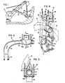
- Fig. 1 is a schematic elevational view, partially in section, of the forward (working) end of a power shovel;
- Fig. 2 is an enlarged fragmentary view taken along the sight line 2-2 of Fig. 1 and which essentially shows the inventive bail assembly in front elevation;
- Fig. 3 is a fragmentary sectional view taken along the sight line 3-3 applied to Fig. 2; and
- Fig. 4 is an exploded perspective view of the lifting hitch of the invention shown in conjunction with a fragment of a bail illustrated in dashed line.
- In the illustration given and with reference first to Fig. 1, the
numeral 10 designates generally a power shovel equipped with a lifting boom 11 havingcable sheaves 12 at the outer boom end, the inner end of the boom being mounted in the cab 13. - A
dipper stick 14 equipped with adipper 15 at the outer end thereof is pivotally mounted on the boom 11 and is equipped with abail 16. Lifting cables generally designated 17 are connected between the bail and are entrained over thesheaves 12 for connection to a winch (not shown) within the prime mover of thepower shovel 10. This environmental description for the invention is generally conventional and has been utilized in the construction of power shovels for many years. - The
bail 16 can be seen in enlarged form in Fig. 2 and includes a generally U-shaped mem- . ber-the bail being shown only fragmentarily in order to conserve drawing space. Thebail 16 includes a pair oflegs 18 which are equipped with pivotal connections at the lower ends thereof as at 19 for pivotal engagement with the sides of thedipper 15. The bail further includes an integral, connectingbight 20 extending between the two dependinglegs 18. - The
bight 20 has a centralcylindrical portion 21 which can be best appreciated from a consideration of the central portion of Fig. 3. Advantageously, the bail can be cast or formed to provide such a central cylindrical section. Rotatably mounted on the bail central cylindrical section is a lifting hitch generally designated 22. - The parts of the lifting hitch can be appreciated best from a consideration of Fig. 4 where the same are shown in exploded form. In Fig. 4, the numeral 22a-see the lower right hand portion--designates a generally U-shaped bracket which partially encircles the central
cylindrical portion 21 of thebight 20. The bracket 22a has a pair of upstanding arms as at 23 and is closed across the top thereof by means of a closure 24-see the upper portion of Fig. 4. - In the illustration given, the
closure 24 is equipped with a dependingportion 25 which is internally contoured to a segmental cylindrical configuration. In like fashion, the bracket 22a is similarly contoured as at 26. These provide complementary surfaces for the mounting of a splitcylindrical bearing 27 which encircles the centralcylindrical section 21 of thebight 20. In the illustration given fourbolts 28 are employed to secure theclosure 24 to the bracket 22a. - Each of the
arms 23 of the bracket 22a are equipped on the outer sides thereof-relative to the bight 20-with a D-ring as at 30. The D-ring is essentially a half sheave and receives the looped bottom end of a cable such as that designated 17a in Fig. 4. The open bottom side of each D-ring is closed by anarcuate member 31 which is boltably secured to theclosure 24 by means ofbolts 32. - Provided on the upper surface of the
closure 24 is a bumper means 33 which can be seen in Fig. 3 to be coming into close proximity to the boom sheaves 12-the bumber means being advantageously arcuately curved as seen in Fig. 3 corresponding to the curvature of the sheave means 12. - Through the use of the invention, several significant advantages are achieved. These include reduced weight, reduced maintenance on rope and fewer bushed pivot points and the ability to raise the dipper closer to the machine boom sheave for material loading ease and clearance over trucks.
- While in the foregoing specification a detailed description of an embodiment of the invention has been set down for the purpose of understanding, many variations in the details herein given may be made by those skilled in the art without departing from the scope of the invention.
Claims (6)
Priority Applications (3)
| Application Number | Priority Date | Filing Date | Title |
|---|---|---|---|
| US06/728,326 US4597713A (en) | 1985-04-29 | 1985-04-29 | Shovel dipper bail assembly |
| DE8686108661T DE3661556D1 (en) | 1986-06-25 | 1986-06-25 | Shovel dipper bail assembly |
| EP19860108661 EP0250618B1 (en) | 1986-06-25 | 1986-06-25 | Shovel dipper bail assembly |
Applications Claiming Priority (1)
| Application Number | Priority Date | Filing Date | Title |
|---|---|---|---|
| EP19860108661 EP0250618B1 (en) | 1986-06-25 | 1986-06-25 | Shovel dipper bail assembly |
Publications (2)
| Publication Number | Publication Date |
|---|---|
| EP0250618A1 EP0250618A1 (en) | 1988-01-07 |
| EP0250618B1 true EP0250618B1 (en) | 1988-12-28 |
Family
ID=8195220
Family Applications (1)
| Application Number | Title | Priority Date | Filing Date |
|---|---|---|---|
| EP19860108661 Expired EP0250618B1 (en) | 1985-04-29 | 1986-06-25 | Shovel dipper bail assembly |
Country Status (2)
| Country | Link |
|---|---|
| EP (1) | EP0250618B1 (en) |
| DE (1) | DE3661556D1 (en) |
Families Citing this family (1)
| Publication number | Priority date | Publication date | Assignee | Title |
|---|---|---|---|---|
| AU2013206737B2 (en) * | 2012-07-09 | 2017-09-07 | Joy Global Surface Mining Inc | Bail assembly |
Family Cites Families (5)
| Publication number | Priority date | Publication date | Assignee | Title |
|---|---|---|---|---|
| US1689122A (en) * | 1928-10-23 | Assigkniob to the marion steam shovel | ||
| GB140411A (en) * | 1916-07-07 | 1920-08-19 | Ball Engine Co | Improvements in and relating to pulley blocks |
| US1609372A (en) * | 1925-08-01 | 1926-12-07 | Koehring Co | Power-shovel dipper |
| US2947430A (en) * | 1955-08-30 | 1960-08-02 | Harnischfeger Corp | Hoist cable equalizer assembly |
| US3877581A (en) * | 1973-02-20 | 1975-04-15 | Unit Rig & Equip | Tension Equalizer |
-
1986
- 1986-06-25 DE DE8686108661T patent/DE3661556D1/en not_active Expired
- 1986-06-25 EP EP19860108661 patent/EP0250618B1/en not_active Expired
Also Published As
| Publication number | Publication date |
|---|---|
| EP0250618A1 (en) | 1988-01-07 |
| DE3661556D1 (en) | 1989-02-02 |
Similar Documents
| Publication | Publication Date | Title |
|---|---|---|
| US5423625A (en) | Boom/arm coupler for excavator | |
| US4944102A (en) | High production system bucket | |
| CA2121774A1 (en) | Scissors type dipper bucket enhancing hoist rope closure for power shovels | |
| CA2141856A1 (en) | Dragline excavator bucket and rigging | |
| CN213539113U (en) | Hoisting Rope Connectors, Connecting Assemblies and Digging Assemblies for Rope Excavators | |
| US6484423B1 (en) | Dragline rigging system | |
| US4597713A (en) | Shovel dipper bail assembly | |
| GB2040260A (en) | Boom apparatus | |
| US3912230A (en) | Dragrope fairlead assembly | |
| CA1181369A (en) | Skidding grapple having winch-like capability | |
| EP0250618A1 (en) | Shovel dipper bail assembly | |
| US4495717A (en) | Combination spacer and lifting device for backhoe machinery | |
| CA1249316A (en) | Shovel dipper bail assembly | |
| AU727519B2 (en) | Dumping System for a Dragline Bucket | |
| US3275301A (en) | Sheave pulley | |
| FI79075B (en) | KRAN FOER TUNGA LASTER, SPECIELLT EN HAVSKRAN OCH FOERFARANDE FOER FOERANKRANDE AV DENNA. | |
| WO2018153934A1 (en) | Device for an excavator | |
| US7037064B2 (en) | Grapple assembly for excavating machines and the like | |
| CN223688011U (en) | Lower bolster structure of grab bucket | |
| US1898810A (en) | Excavator | |
| US5209535A (en) | Power bucket | |
| CA1219453A (en) | Three point hitch rock and root puller | |
| US1819590A (en) | Excavating machine | |
| CA2060473A1 (en) | Pivoted handle dipper shovel with hydraulic crowders and wire rope pulley | |
| SU1082904A1 (en) | Working equipment of dragline |
Legal Events
| Date | Code | Title | Description |
|---|---|---|---|
| PUAI | Public reference made under article 153(3) epc to a published international application that has entered the european phase |
Free format text: ORIGINAL CODE: 0009012 |
|
| 17P | Request for examination filed |
Effective date: 19870409 |
|
| AK | Designated contracting states |
Kind code of ref document: A1 Designated state(s): DE FR GB SE |
|
| 17Q | First examination report despatched |
Effective date: 19880506 |
|
| GRAA | (expected) grant |
Free format text: ORIGINAL CODE: 0009210 |
|
| AK | Designated contracting states |
Kind code of ref document: B1 Designated state(s): DE FR GB SE |
|
| REF | Corresponds to: |
Ref document number: 3661556 Country of ref document: DE Date of ref document: 19890202 |
|
| ET | Fr: translation filed | ||
| RAP2 | Party data changed (patent owner data changed or rights of a patent transferred) |
Owner name: NEWESCO CORPORATION |
|
| PLBE | No opposition filed within time limit |
Free format text: ORIGINAL CODE: 0009261 |
|
| STAA | Information on the status of an ep patent application or granted ep patent |
Free format text: STATUS: NO OPPOSITION FILED WITHIN TIME LIMIT |
|
| 26N | No opposition filed | ||
| PGFP | Annual fee paid to national office [announced via postgrant information from national office to epo] |
Ref country code: FR Payment date: 19900515 Year of fee payment: 5 |
|
| PGFP | Annual fee paid to national office [announced via postgrant information from national office to epo] |
Ref country code: SE Payment date: 19900521 Year of fee payment: 5 Ref country code: DE Payment date: 19900521 Year of fee payment: 5 |
|
| PGFP | Annual fee paid to national office [announced via postgrant information from national office to epo] |
Ref country code: GB Payment date: 19900525 Year of fee payment: 5 |
|
| REG | Reference to a national code |
Ref country code: FR Ref legal event code: CD |
|
| PG25 | Lapsed in a contracting state [announced via postgrant information from national office to epo] |
Ref country code: GB Effective date: 19910625 |
|
| PG25 | Lapsed in a contracting state [announced via postgrant information from national office to epo] |
Ref country code: SE Effective date: 19910626 |
|
| GBPC | Gb: european patent ceased through non-payment of renewal fee | ||
| PG25 | Lapsed in a contracting state [announced via postgrant information from national office to epo] |
Ref country code: FR Effective date: 19920228 |
|
| PG25 | Lapsed in a contracting state [announced via postgrant information from national office to epo] |
Ref country code: DE Effective date: 19920401 |
|
| REG | Reference to a national code |
Ref country code: FR Ref legal event code: ST |
|
| EUG | Se: european patent has lapsed |
Ref document number: 86108661.9 Effective date: 19920109 |