EP0250059B1 - Method for determining fracture toughness of rock by core boring - Google Patents
Method for determining fracture toughness of rock by core boring Download PDFInfo
- Publication number
- EP0250059B1 EP0250059B1 EP87301548A EP87301548A EP0250059B1 EP 0250059 B1 EP0250059 B1 EP 0250059B1 EP 87301548 A EP87301548 A EP 87301548A EP 87301548 A EP87301548 A EP 87301548A EP 0250059 B1 EP0250059 B1 EP 0250059B1
- Authority
- EP
- European Patent Office
- Prior art keywords
- rock
- fracture toughness
- bit
- test piece
- core
- Prior art date
- Legal status (The legal status is an assumption and is not a legal conclusion. Google has not performed a legal analysis and makes no representation as to the accuracy of the status listed.)
- Expired - Lifetime
Links
- 239000011435 rock Substances 0.000 title claims description 50
- 238000000034 method Methods 0.000 title claims description 30
- 238000012360 testing method Methods 0.000 claims description 42
- 238000005553 drilling Methods 0.000 claims description 23
- 239000004575 stone Substances 0.000 claims description 22
- 238000007656 fracture toughness test Methods 0.000 claims 1
- 238000010998 test method Methods 0.000 description 9
- 230000000704 physical effect Effects 0.000 description 6
- 238000012937 correction Methods 0.000 description 5
- 229910003460 diamond Inorganic materials 0.000 description 5
- 239000010432 diamond Substances 0.000 description 5
- 230000012010 growth Effects 0.000 description 5
- 238000005259 measurement Methods 0.000 description 5
- 238000007657 chevron notch test Methods 0.000 description 4
- 238000013001 point bending Methods 0.000 description 4
- 238000013461 design Methods 0.000 description 3
- 230000006399 behavior Effects 0.000 description 2
- 238000010586 diagram Methods 0.000 description 2
- 238000006073 displacement reaction Methods 0.000 description 2
- 238000006467 substitution reaction Methods 0.000 description 2
- 238000013459 approach Methods 0.000 description 1
- 238000010276 construction Methods 0.000 description 1
- 230000006870 function Effects 0.000 description 1
- 239000011159 matrix material Substances 0.000 description 1
- 238000012986 modification Methods 0.000 description 1
- 230000004048 modification Effects 0.000 description 1
- 238000012956 testing procedure Methods 0.000 description 1
- XLYOFNOQVPJJNP-UHFFFAOYSA-N water Substances O XLYOFNOQVPJJNP-UHFFFAOYSA-N 0.000 description 1
Images


Classifications
-
- E—FIXED CONSTRUCTIONS
- E21—EARTH OR ROCK DRILLING; MINING
- E21B—EARTH OR ROCK DRILLING; OBTAINING OIL, GAS, WATER, SOLUBLE OR MELTABLE MATERIALS OR A SLURRY OF MINERALS FROM WELLS
- E21B49/00—Testing the nature of borehole walls; Formation testing; Methods or apparatus for obtaining samples of soil or well fluids, specially adapted to earth drilling or wells
- E21B49/006—Measuring wall stresses in the borehole
-
- E—FIXED CONSTRUCTIONS
- E21—EARTH OR ROCK DRILLING; MINING
- E21B—EARTH OR ROCK DRILLING; OBTAINING OIL, GAS, WATER, SOLUBLE OR MELTABLE MATERIALS OR A SLURRY OF MINERALS FROM WELLS
- E21B44/00—Automatic control systems specially adapted for drilling operations, i.e. self-operating systems which function to carry out or modify a drilling operation without intervention of a human operator, e.g. computer-controlled drilling systems; Systems specially adapted for monitoring a plurality of drilling variables or conditions
-
- E—FIXED CONSTRUCTIONS
- E21—EARTH OR ROCK DRILLING; MINING
- E21B—EARTH OR ROCK DRILLING; OBTAINING OIL, GAS, WATER, SOLUBLE OR MELTABLE MATERIALS OR A SLURRY OF MINERALS FROM WELLS
- E21B49/00—Testing the nature of borehole walls; Formation testing; Methods or apparatus for obtaining samples of soil or well fluids, specially adapted to earth drilling or wells
- E21B49/02—Testing the nature of borehole walls; Formation testing; Methods or apparatus for obtaining samples of soil or well fluids, specially adapted to earth drilling or wells by mechanically taking samples of the soil
Definitions
- This invention relates to a method for determining toughness against fracture (to be referred to as "fracture toughness", hereinafter) of rock by a core boring, which method is particularly useful as a means for logging of underground rock.
- ISRM International Society for Rock Mechanics proposes a core test method for determining fracture toughness of underground rock by using a core bored therefrom.
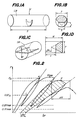
- This test method allows the use of either of two types of test piece; namely a three-point bending test piece CB with a chevron notch as shown in Fig. lA and Fig. lB, and a short rod test piece SR with a chevron notch as shown in Fig. lC and Fig. lD.
- Stress intensity factor K of the test piece is given as follows.
- T is the diameter of the test piece
- S is the spacing between support points of the test piece
- F is the load to the test piece
- Y c ⁇ and f are correction factors.
- the core test method of ISRM provides for two levels, i.e., level I and level II, from the standpoint of the ease of testing procedure.
- the philosophy of the level I test for evaluating the fracture toughness assumes that a crack propagates with a constant value of the stress intensity factor K at the tip of the crack, and the fracture toughness is determined at an evaluating point where the above corrections factors Y c ⁇ and f are minimized or a maximum load F max is applied. Crack length a c at the evaluating point depends only on the shape of the test piece.
- the level I test gives the following fracture toughness K CB or K SR for the above test piece.
- K CB A min F max /T l.5 (3)
- K SR 24.0F max /T l.5 (4)
- a min 0.25(S/T)[7.34+28.6(t0/T)+39.4(t0/T)2]
- Fig. 2 shows load-displacement (F- ⁇ F ) curves for repeated load-unload cycles. Compliance of a test piece at a load stage F H is defined as the slope of a straight line which passes through both a point H for the load stage F H and a point L for one-half of the load stage (0.5F H ).
- the evaluating point load F c and a non-linearity correction factor p are determined, and the fracture toughness K c after non-linearity correction is calculated by the following equation for both the three-point bending test piece CB and the short rod test piece SR.
- p ( ⁇ X0/ ⁇ X)
- the ISRM core test method requires one test piece for each determination of the fracture toughness, e.g., one test piece for each portion of the underground rock.
- knowledge on the distribution of the fracture toughness over a range of underground depth is necessary.
- the ISRM core test method takes much time and labor for testing one core for determining the fracture toughness at one portion of rock, and this method is not suitable for determining the values of the fracture toughness of underground rock at different portions thereof.
- the conventional ISRM core test method has a shortcoming in that it does not provide any means for continuous measurement of the fracture toughness of underground rock over a range of depth.
- an object of the present invention is to obviate the above-mentioned shortcoming of the prior art by providing a novel method for continuous measurement of the fracture toughness of underground rock in a simple manner over a range of depth, which method uses data collectable during core boring.
- the fracture toughness of underground rock can be determined in an on-line manner while a bore-hole is being drilled.
- the method provides an important fundamental technique for geothermal exploitation from underground hot dry rock.
- the method of the invention stores physical properties of a core boring machine such as type and dimensions of a coring bit and others, measures operating conditions of the core boring machine such as drilling speed and others, and calculates the fracture toughness of rock based on the thus stored physical properties and the thus measured operating conditions.
- bit face width B of a coring bit of the core boring machine and number of rows ⁇ of face stones on the coring bit are measured and stored on a memory.
- the rock fracture toughness is once determined through the ISRM method by using a test piece that is prepared from a core produced by the core boring while measuring and storing the bit revolving speed N of the coring bit, the supply pressure Q thereto, and the drilling speed L when the core is taken.
- the fracture toughness K IC of the test piece is determined by applying a load thereto until fracture thereof and measuring the load at the fracture.
- the pressure effectivity factor h thus determined is stored in the memory.
- the value of fracture toughness K IC of the rock at the arbitrary portion is determined by calculation of the above equation while using the stored values of the bit face width B, the number of rows ⁇ of face stones, and the pressure effectivity factor h, as well as measured values of the bit revolving speed N, the supply pressure Q, and the drilling speed L thereat.
- Fig. lA is a schematic perspective view of a three-point bending test piece CB
- Fig. lB is a sectional view of the test piece CB at a chevron notch thereof
- Fig. lC is a schematic perspective view of a short rod test piece SR
- Fig. lD is a sectional view of the test piece SR at a chevron notch thereof
- Fig. 2 is a graph showing load-displacement (F- ⁇ F ) curves
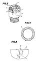
- Fig. 3 is a partially cutaway schematic perspective view of a diamond coring bit
- Fig. lA is a schematic perspective view of a three-point bending test piece CB
- Fig. lB is a sectional view of the test piece CB at a chevron notch thereof
- Fig. lC is a schematic perspective view of a short rod test piece SR
- Fig. lD is a sectional view of the test piece SR at
- FIG. 4 is an end view of the diamond coring bit, showing the manner in which face stones are embedded thereon;
- Fig. 5 is a diagrammatic illustration of the relationship between an edge formed of face stones and an edge crack produced on rock surface;
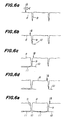
- Fig. 6 shows curves (a), (b), (c), (d), and (e) which illustrate the relation between the load moving direction E and the growths of an edge crack 9, a horizontal forward crack l0 and a horizontal backward crack ll;
- Fig. 7 is a graph showing the variations of the maximum intensity of singularity of circumferential stress K and the fracture toughness K IC with increase of the crack length a;
- Fig. 8 is a flow chart of the method for determining rock fracture toughness K IC by core boring according to the invention; and
- Fig. 9 is an overall block diagram of a system for measuring rock fracture toughness by the method according to the invention.
- l is a coring bit such as a diamond coring bit
- 2 is a shank
- 3 is a gauge stone
- 4 is a face stone
- 5 is a kicker stone
- 6 is a water groove
- 7 is a matrix
- 8 is a drilled surface of rock
- 9 is an edge crack
- l0 is a horizontal forward crack
- ll is a horizontal backward crack.
- Fig. 3 shows a partial cutaway schematic perspective view of a coring bit l which is formed as a surface bit
- Fig. 4 shows the manner in which face stones 4 are embedded on the surface of the coring bit l.
- the face stones 4 are so embedded that they are aligned regularly in rows.
- one row of the face stones 4 aligned along a line which extends between inner periphery and outer periphery of the coring bit l is treated as a cutter edge for drilling the rock.
- h is a pressure effectivity factor which represents that part of the applied pressure Q is actually applied to the face stones 4.
- a number of small edge cracks 9 are generated on drilled surface 8 of the rock.
- the rock be a semi-infinite isotropic and homogeneous elastic medium and the small edge cracks 9 be perpendicular to the surface of the semi-infinite elastic medium.
- Fig. 5 shows a two-dimensional model of a cutter edge formed of the row of face stones 4 and the edge crack 9. Curves (a) through (e) of Fig. 6 show the process in which rock is drilled by the movement of the cutter edge to which edge a concentrated load q is applied.
- a crack occurs when the maximum value of the intensity of singularity of circumferential stress in the proximity of the crack tip exceeds the fracture toughness, and such crack grows from the crack tip in the direction of the maximum value of the intensity of singularity.
- Fig. 7 shows the relationship between the maximum value K of intensity of singularity of circumferential stress and the fracture toughness K IC for different crack lengths a.
- the above-mentioned excess load K* increases with decrease of the crack length a.
- the probability of the rock peeling is proportional to the excess load K*
- the probability density function of occurrence of the rock peeling at the crack length a is given by
- the mean crack length a m for producing the rock peeling becomes
- the drilling rate L or drilling length per unit time
- One test piece CB of Fig. lA or SR of Fig. lC is prepared by using a core taken from a portion of rock, and its fracture toughness K IC is determined by the ISRM core test method.
- the pressure effectivity factor h of the core boring machine is determined by the equation (l5); namely, by substituting the following data in the equation (l5), i.e., the thus measured fracture toughness K IC , the stored bit face width B and the number of rows ⁇ of the face stones 4, the measured bit revolving speed N, the supply pressure Q, and the drilling speed L at the above-mentioned portion of the rock.
- the fracture toughness K IC at an arbitrary portion of underground rock can be determined by substituting the bit revolving speed N, the supply pressure Q, and the drilling speed L at the arbitrary portion in the equation (l5).
- the fracture toughness K IC at an arbitrary portion of underground rock can be determined by substituting the following data into the equation (l5), i.e., the physical properties of the core boring machine including the bit face width B, the number of face stone rows ⁇ , and the pressure effectivity factor h, as well as its operating conditions including the bit revolving speed N, the supply pressure Q, and the drilling speed L at the arbitrary portion.
- the flow chart of Fig. 8 shows the steps of the process for determining the fracture toughness K IC in both of the above cases (i) and (ii).
- FIG. 9 shows an overall block diagram of a rock fracture toughness measuring system by core boring based on the method according to the invention.
- a core boring machine l2 has a tachometer l3 for measuring the bit revolving speed N, a pressure gauge l4 for measuring the supply pressure Q, a drilling speed meter l5 for measuring the drilling speed L, and a depth meter l6 for measuring the depth D.
- Signals representing the measured values of the bit revolving speed N, the supply pressure Q, the drilling speed L, and the depth D are delivered to a computer 2l and stored thereat as the coring bit drills into the rock.
- the bit face width B and the number of face stone rows ⁇ of the coring bit of the boring machine are measured beforehand and stored in a memory l7.
- the memory l7 may or may not be a part of the computer 2l.
- a core is taken from a certain portion of the rock, e.g., at a certain depth thereof, and the bit revolving speed B, the supply pressure Q, and the drilling speed L of the coring bit at the certain portion are measured and stored as shown by a block l8.
- the fracture toughness K IC of the core is measured by applying the ISRM test method as shown by a block l9.
- a block 20 is to determine the pressure effectivity factor h by the equation (l5); namely, by substituting the bit revolving speed N, the supply pressure Q, and the drilling speed L from the block l8 and the fracture toughness K IC from the block l9 into the equation (l5).
- the pressure effectivity factor h thus calculated is sent to the computer 2l for storage.
- Test cores were obtained by drilling a bore-hole at three depths in HACHIMANTAI TEST FIELD of TOHOKU UNIVERSITY. For comparison, the fracture toughness of the test cores were determined both by the ISRM core test method and by the method of the invention.
- the ISRM core test was applied to the test cores so as to determine their fracture toughness. The result is shown in Table 2.
- the pressure effectivity factor h for each test core was calculated by using the equation (l5) and the related data; namely, the thus determined fracture toughness, the bit revolving speed N, the supply pressure Q, and the drilling speed L of Table l.
- the bit face width B was l6.5 mm and the number of face stone rows ⁇ was 54. Consequently, an average pressure effectivity factor h of 0.34 was obtained.
- the fracture toughness of the test cores was calculated by the method of the invention; namely, by substituting the data of Table l and the average pressure effectivity factor into the equation (l5). The result is also shown in Table 2.
- the present invention provides a method for determining rock fracture toughness K IC at different locations by calculation in an automatic and continuous manner, possibly during the core boring; namely, by using boring machine data such as the bit face width B and the number of face stone rows ⁇ and by measuring the operating conditions, such as the bit revolving speed N, the supply pressure Q, and the drilling speed L.
- the invention facilitates simplification, automatic measurement, continuous measurement, and automatic recording of rock fracture toughness K IC .
Landscapes
- Life Sciences & Earth Sciences (AREA)
- Geology (AREA)
- Engineering & Computer Science (AREA)
- Mining & Mineral Resources (AREA)
- Physics & Mathematics (AREA)
- Environmental & Geological Engineering (AREA)
- Fluid Mechanics (AREA)
- General Life Sciences & Earth Sciences (AREA)
- Geochemistry & Mineralogy (AREA)
- Soil Sciences (AREA)
- Investigation Of Foundation Soil And Reinforcement Of Foundation Soil By Compacting Or Drainage (AREA)
- Earth Drilling (AREA)
- Investigating Strength Of Materials By Application Of Mechanical Stress (AREA)
Description
- This invention relates to a method for determining toughness against fracture (to be referred to as "fracture toughness", hereinafter) of rock by a core boring, which method is particularly useful as a means for logging of underground rock.
- To exploit geothermal energy from hot dry rock, engineering to facilitate the design of underground heat-exchange surface (crack surface) is necessary. Knowledge of the fracture toughness of rock is indispensable for such engineering because it is one of the most fundamental physical properties which rule behavior of underground cracks.
- ISRM (International Society for Rock Mechanics) proposes a core test method for determining fracture toughness of underground rock by using a core bored therefrom. This test method allows the use of either of two types of test piece; namely a three-point bending test piece CB with a chevron notch as shown in Fig. lA and Fig. lB, and a short rod test piece SR with a chevron notch as shown in Fig. lC and Fig. lD. Stress intensity factor K of the test piece is given as follows.
For the three-point bending test piece CB:

For the short rod test piece SR:

Here, T is the diameter of the test piece, S is the spacing between support points of the test piece, F is the load to the test piece, and Ycʹ and f are correction factors. - The core test method of ISRM provides for two levels, i.e., level I and level II, from the standpoint of the ease of testing procedure.
- The philosophy of the level I test for evaluating the fracture toughness assumes that a crack propagates with a constant value of the stress intensity factor K at the tip of the crack, and the fracture toughness is determined at an evaluating point where the above corrections factors Ycʹ and f are minimized or a maximum load Fmax is applied. Crack length ac at the evaluating point depends only on the shape of the test piece. The level I test gives the following fracture toughness KCB or KSR for the above test piece.


Here,

- In the level II test, non-linearity correction is applied to the fracture toughness KCB and KSR obtained by the level I test. It is proposed to determine an evaluating point load Fc which corresponds to a critical crack length ac based on an unloading compliance method. Fig. 2 shows load-displacement

- Based on such linearized compliance, the evaluating point load Fc and a non-linearity correction factor p are determined, and the fracture toughness Kc after non-linearity correction is calculated by the following equation for both the three-point bending test piece CB and the short rod test piece SR.


- Thus, the ISRM core test method requires one test piece for each determination of the fracture toughness, e.g., one test piece for each portion of the underground rock. On the other hand, in order to design underground heat-exchange surfaces, knowledge on the distribution of the fracture toughness over a range of underground depth is necessary. The ISRM core test method takes much time and labor for testing one core for determining the fracture toughness at one portion of rock, and this method is not suitable for determining the values of the fracture toughness of underground rock at different portions thereof.
- In short, the conventional ISRM core test method has a shortcoming in that it does not provide any means for continuous measurement of the fracture toughness of underground rock over a range of depth.
- Therefore, an object of the present invention is to obviate the above-mentioned shortcoming of the prior art by providing a novel method for continuous measurement of the fracture toughness of underground rock in a simple manner over a range of depth, which method uses data collectable during core boring.
- With the method of the invention, the fracture toughness of underground rock can be determined in an on-line manner while a bore-hole is being drilled. Thus, the method provides an important fundamental technique for geothermal exploitation from underground hot dry rock.
- In essence, the method of the invention stores physical properties of a core boring machine such as type and dimensions of a coring bit and others, measures operating conditions of the core boring machine such as drilling speed and others, and calculates the fracture toughness of rock based on the thus stored physical properties and the thus measured operating conditions.
- More particularly, in a method for determining fracture toughness of rock by a core boring according to the invention, bit face width B of a coring bit of the core boring machine and number of rows ε of face stones on the coring bit are measured and stored on a memory. To facilitate the determination of pressure effectivity factor h of the core boring machine which will be defined hereinafter by referring to the equation (6), the rock fracture toughness is once determined through the ISRM method by using a test piece that is prepared from a core produced by the core boring while measuring and storing the bit revolving speed N of the coring bit, the supply pressure Q thereto, and the drilling speed L when the core is taken.
- In accordance with the ISRM method, the fracture toughness KIC of the test piece is determined by applying a load thereto until fracture thereof and measuring the load at the fracture.
- The pressure effectivity factor h of the core boring machine is calculated from the thus determined fracture toughness KIC of the test piece by an equation of

The pressure effectivity factor h thus determined is stored in the memory. - Further boring is effected at an arbitrary portion of the rock by the core boring machine, and the value of fracture toughness KIC of the rock at the arbitrary portion is determined by calculation of the above equation while using the stored values of the bit face width B, the number of rows ε of face stones, and the pressure effectivity factor h, as well as measured values of the bit revolving speed N, the supply pressure Q, and the drilling speed L thereat.
- For a better understanding of the invention, reference is made to the accompanying drawings, in which
Fig. lA is a schematic perspective view of a three-point bending test piece CB;
Fig. lB is a sectional view of the test piece CB at a chevron notch thereof;
Fig. lC is a schematic perspective view of a short rod test piece SR;
Fig. lD is a sectional view of the test piece SR at a chevron notch thereof;
Fig. 2 is a graph showing load-displacement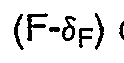
Fig. 3 is a partially cutaway schematic perspective view of a diamond coring bit;
Fig. 4 is an end view of the diamond coring bit, showing the manner in which face stones are embedded thereon;
Fig. 5 is a diagrammatic illustration of the relationship between an edge formed of face stones and an edge crack produced on rock surface;
Fig. 6 shows curves (a), (b), (c), (d), and (e) which illustrate the relation between the load moving direction E and the growths of anedge crack 9, a horizontal forward crack l0 and a horizontal backward crack ll;
Fig. 7 is a graph showing the variations of the maximum intensity of singularity of circumferential stress K and the fracture toughness KIC with increase of the crack length a;
Fig. 8 is a flow chart of the method for determining rock fracture toughness KIC by core boring according to the invention; and
Fig. 9 is an overall block diagram of a system for measuring rock fracture toughness by the method according to the invention.
- Throughout different views of the drawing, l is a coring bit such as a diamond coring bit, 2 is a shank, 3 is a gauge stone, 4 is a face stone, 5 is a kicker stone, 6 is a water groove, 7 is a matrix, 8 is a drilled surface of rock, 9 is an edge crack, l0 is a horizontal forward crack, and ll is a horizontal backward crack.
- The theory of the method according to the invention will now be described in detail by referring the accompanying drawings.
- There are two types of diamond bits which are used as coring bit l in a core boring machine of the invention; namely a surface bit and an impregnated bit. Fig. 3 shows a partial cutaway schematic perspective view of a coring bit l which is formed as a surface bit, and Fig. 4 shows the manner in which face
stones 4 are embedded on the surface of the coring bit l. As can be seen from Fig. 4, theface stones 4 are so embedded that they are aligned regularly in rows. In the ensuing analysis, one row of theface stones 4 aligned along a line which extends between inner periphery and outer periphery of the coring bit l is treated as a cutter edge for drilling the rock. - If the coring bit l has a bit face width B and ε rows of
face stones 4 embedded thereon, and if pressure Q is applied to the coring bit as a total load (to be referred to as "applied pressure"), then the load per unit length of one row of theface stones 4 is given by the following equation.
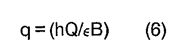
Here, h is a pressure effectivity factor which represents that part of the applied pressure Q is actually applied to theface stones 4. - Referring to Fig. 5, a number of
small edge cracks 9 are generated on drilledsurface 8 of the rock. In the ensuing analysis, it is assumed that the rock be a semi-infinite isotropic and homogeneous elastic medium and thesmall edge cracks 9 be perpendicular to the surface of the semi-infinite elastic medium. Fig. 5 shows a two-dimensional model of a cutter edge formed of the row offace stones 4 and theedge crack 9. Curves (a) through (e) of Fig. 6 show the process in which rock is drilled by the movement of the cutter edge to which edge a concentrated load q is applied. - More particularly, when the concentrated load q approaches the
edge crack 9 on the drilledsurface 8 as shown by the arrow E of the curve (a) of Fig. 6, the tip of theedge crack 9 is so kinked as to cause growth of a horizontal forward crack l0 as shown in the curve (b) of the figure. When the concentrated load q passes theedge crack 9 and reaches the position as shown in the curve (c) of Fig. 6, a horizontal backward crack ll is generated in the contrary or rearward direction, and the horizontal backward crack ll extends to and joins with a previously formed horizontal forward crack l0 so as to cause peeling of a portion of the rock thereat. As the concentrated load q further moves, the horizontal forward crack l0 and the horizontal backward crack ll similarly grow and ensuing peeling occurs as shown in the curves (d) and (e) of Fig. 6. As a result, the rock is drilled. - To analyze the growth of the horizontal backward crack ll from the tip of the
edge crack 9 immediately after the passage of the concentrated load q through theedge crack 9, it is necessary to find the stress intensity factor at the tip of theedge crack 9. Referring to Fig. 5, when the concentrated load q is at a shoulder portion of the two-dimensional edge crack 9 with a length a, the stress intensity factor KI for mode I and the stress intensity factor KII for mode II at the tip of theedge crack 9 are given as follows.

- According to the Erdogan-Sih's criterion for crack growth, a crack occurs when the maximum value of the intensity of singularity of circumferential stress in the proximity of the crack tip exceeds the fracture toughness, and such crack grows from the crack tip in the direction of the maximum value of the intensity of singularity. Referring to Fig. 5, the above criterion also suggests that the maximum value K of the intensity of singularity of the stress and the angle ϑ between the elongation of the
edge crack 9 and the direction of the crack growth are given by

- When the maximum value K of intensity of singularity of the circumferential stress given by the equation (9) exceeds the fracture toughness KIC of the rock, the
edge crack 9 grows. Thus, when theedge crack 9 grows, the excess load K* given by the following equation assumes zero or a positive value.
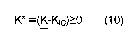
- Fig. 7 shows the relationship between the maximum value K of intensity of singularity of circumferential stress and the fracture toughness KIC for different crack lengths a. As can be seen from Fig. 7, the above-mentioned excess load K* increases with decrease of the crack length a. If it is assumed that the probability of the rock peeling is proportional to the excess load K*, the probability density function of occurrence of the rock peeling at the crack length a is given by


- Substitution of the equations (6), (9), (l0), and (l2) in the equation (ll) gives

- Accordingly, the drilling rate L, or drilling length per unit time, is given by

- When the operating conditions of the core boring machine including the bit revolving speed N, the applied pressure Q, and the drilling speed L are measured, the fracture toughness Kc can be determined in the following manner by using the equation (l4)

- The process for determining the fracture toughness will now be described by referring to the flow chart of Fig. 8. Before the start of actual measurement, the physical properties of the core boring machine, i.e., the bit face width B and the number of rows ε of the
face stones 4, are measured and stored in a computer. Depending on weather the above-mentioned pressure effectivity factor h is known or not, either of the following routes is selected. - One test piece CB of Fig. lA or SR of Fig. lC is prepared by using a core taken from a portion of rock, and its fracture toughness KIC is determined by the ISRM core test method. The pressure effectivity factor h of the core boring machine is determined by the equation (l5); namely, by substituting the following data in the equation (l5), i.e., the thus measured fracture toughness KIC, the stored bit face width B and the number of rows ε of the
face stones 4, the measured bit revolving speed N, the supply pressure Q, and the drilling speed L at the above-mentioned portion of the rock. - Once the pressure effectivity factor h of the core boring machine is known, the fracture toughness KIC at an arbitrary portion of underground rock can be determined by substituting the bit revolving speed N, the supply pressure Q, and the drilling speed L at the arbitrary portion in the equation (l5).
- In this case, the fracture toughness KIC at an arbitrary portion of underground rock can be determined by substituting the following data into the equation (l5), i.e., the physical properties of the core boring machine including the bit face width B, the number of face stone rows ε, and the pressure effectivity factor h, as well as its operating conditions including the bit revolving speed N, the supply pressure Q, and the drilling speed L at the arbitrary portion.
- The flow chart of Fig. 8 shows the steps of the process for determining the fracture toughness KIC in both of the above cases (i) and (ii).
- Fig. 9 shows an overall block diagram of a rock fracture toughness measuring system by core boring based on the method according to the invention. A core boring machine l2 has a tachometer l3 for measuring the bit revolving speed N, a pressure gauge l4 for measuring the supply pressure Q, a drilling speed meter l5 for measuring the drilling speed L, and a depth meter l6 for measuring the depth D. Signals representing the measured values of the bit revolving speed N, the supply pressure Q, the drilling speed L, and the depth D are delivered to a computer 2l and stored thereat as the coring bit drills into the rock.
- With the method of the invention, the bit face width B and the number of face stone rows ε of the coring bit of the boring machine are measured beforehand and stored in a memory l7. The memory l7 may or may not be a part of the computer 2l. A core is taken from a certain portion of the rock, e.g., at a certain depth thereof, and the bit revolving speed B, the supply pressure Q, and the drilling speed L of the coring bit at the certain portion are measured and stored as shown by a block l8. The fracture toughness KIC of the core is measured by applying the ISRM test method as shown by a block l9. A
block 20 is to determine the pressure effectivity factor h by the equation (l5); namely, by substituting the bit revolving speed N, the supply pressure Q, and the drilling speed L from the block l8 and the fracture toughness KIC from the block l9 into the equation (l5). The pressure effectivity factor h thus calculated is sent to the computer 2l for storage. - Test cores were obtained by drilling a bore-hole at three depths in HACHIMANTAI TEST FIELD of TOHOKU UNIVERSITY. For comparison, the fracture toughness of the test cores were determined both by the ISRM core test method and by the method of the invention.
- In the drilling of the bore-hole, a wire line coring bit HQl0l was used, which had an outside diameter of l0l mm and an inside diameter of 68 mm and 45 CT of diamond embedded therein. The rock type of the test cores and the conditions for drilling the test cores are summarized in Table l.

- The ISRM core test was applied to the test cores so as to determine their fracture toughness. The result is shown in Table 2.
- The pressure effectivity factor h for each test core was calculated by using the equation (l5) and the related data; namely, the thus determined fracture toughness, the bit revolving speed N, the supply pressure Q, and the drilling speed L of Table l. The bit face width B was l6.5 mm and the number of face stone rows ε was 54. Consequently, an average pressure effectivity factor h of 0.34 was obtained. The fracture toughness of the test cores was calculated by the method of the invention; namely, by substituting the data of Table l and the average pressure effectivity factor into the equation (l5). The result is also shown in Table 2.

- The exploitation of geothermal energy from hot dry rock will become important in the future not only in Japan but also throughout the world. To this end, engineering technique for the design of underground heat exchange surface or crack is necessary, and it is indispensable to have adequate knowledge of the rock fracture toughness which is one of the fundamental physical properties ruling the behavior of underground cracks. Many volcanic countries including Japan have rich resources of geothermal energy, and the present invention is particularly important in those countries.
- As described in detail in the foregoing, the present invention provides a method for determining rock fracture toughness KIC at different locations by calculation in an automatic and continuous manner, possibly during the core boring; namely, by using boring machine data such as the bit face width B and the number of face stone rows ε and by measuring the operating conditions, such as the bit revolving speed N, the supply pressure Q, and the drilling speed L. In short, the invention facilitates simplification, automatic measurement, continuous measurement, and automatic recording of rock fracture toughness KIC.
- Although the invention has been described with a certain degree of particularity by referring to a preferred embodiment, numerous modifications are possible in parts and construction without departing from the scope of the invention as hereinafter claimed.
Claims (1)
- A method for determining fracture toughness of rock by core boring, the method comprising steps of
storing the bit face witdth B of a coring bit and the number of face stone rows ε on the coring bit;
preparing a test piece for fracture toughness measurement by the method of ISRM (International Society for Rock Mechanics) from a core produced by core boring with the coring bit at a portion of rock while measuring and storing the revolving speed N of the coring bit, the pressure Q applied thereto, and the drilling speed L at said portion;
fracturing the test piece by applying a load thereto so as to determine fracture toughness KIC of the test piece from the load and dimensions of the test piece in accordance with the ISRM method;
calculating and storing a pressure effectivity factor h by the equation

determining the fracture toughness KIC of the rock at an arbitrary portion thereof using core boring by using the above equation with the stored values of the number of face stone rows ε , the face width B, and the pressure effectivity factor h, and with measured values of the bit revolving speed N, the applied pressure Q, and the drilling speed L of the boring machine thereat.
Applications Claiming Priority (2)
| Application Number | Priority Date | Filing Date | Title |
|---|---|---|---|
| JP61141358A JPS63594A (en) | 1986-06-19 | 1986-06-19 | Method of calculating fracture toughness value of rock by core boring method |
| JP141358/86 | 1986-06-19 |
Publications (3)
| Publication Number | Publication Date |
|---|---|
| EP0250059A2 EP0250059A2 (en) | 1987-12-23 |
| EP0250059A3 EP0250059A3 (en) | 1989-01-25 |
| EP0250059B1 true EP0250059B1 (en) | 1991-07-03 |
Family
ID=15290121
Family Applications (1)
| Application Number | Title | Priority Date | Filing Date |
|---|---|---|---|
| EP87301548A Expired - Lifetime EP0250059B1 (en) | 1986-06-19 | 1987-02-23 | Method for determining fracture toughness of rock by core boring |
Country Status (4)
| Country | Link |
|---|---|
| US (1) | US4759214A (en) |
| EP (1) | EP0250059B1 (en) |
| JP (1) | JPS63594A (en) |
| DE (1) | DE3771132D1 (en) |
Families Citing this family (8)
| Publication number | Priority date | Publication date | Assignee | Title |
|---|---|---|---|---|
| JPH07329994A (en) * | 1994-06-10 | 1995-12-19 | Yoshida Kogyo Kk <Ykk> | Multiple parallel tube and manufacturing method thereof |
| FR2734315B1 (en) * | 1995-05-15 | 1997-07-04 | Inst Francais Du Petrole | METHOD OF DETERMINING THE DRILLING CONDITIONS INCLUDING A DRILLING MODEL |
| US7195086B2 (en) * | 2004-01-30 | 2007-03-27 | Anna Victorovna Aaron | Anti-tracking earth boring bit with selected varied pitch for overbreak optimization and vibration reduction |
| AU2007224370C1 (en) * | 2006-03-07 | 2013-06-06 | Ground Modelling Technologies Ltd. | Rock core logging |
| CN103590824B (en) * | 2013-10-21 | 2016-02-10 | 中国石油天然气股份有限公司 | Productivity Calculation Method for Horizontal Wells in Tight Gas Reservoirs After Multi-stage Fracturing |
| JP2017025617A (en) * | 2015-07-24 | 2017-02-02 | 国立大学法人東北大学 | Core bit |
| CN112945700B (en) * | 2021-03-19 | 2022-10-04 | 中南大学 | Fracture determination method for anisotropic rock |
| CN114577609B (en) * | 2022-03-18 | 2023-06-16 | 天津大学 | Method for in-situ measurement of I-type fracture toughness of in-situ rock |
Family Cites Families (6)
| Publication number | Priority date | Publication date | Assignee | Title |
|---|---|---|---|---|
| US2555275A (en) * | 1946-05-20 | 1951-05-29 | Core Recorder Inc | Art of well drilling |
| US3440875A (en) * | 1967-06-20 | 1969-04-29 | Continental Oil Co | Method for determining the stress anisotropy in a horizontal plane |
| US3907034A (en) * | 1974-01-28 | 1975-09-23 | Jr George O Suman | Method of drilling and completing a well in an unconsolidated formation |
| FR2485616B1 (en) * | 1980-06-27 | 1986-02-28 | Pk I | SYSTEM FOR AUTOMATICALLY CONTROLLING A ROTATION SOIL DRILLING APPARATUS |
| GB8411361D0 (en) * | 1984-05-03 | 1984-06-06 | Schlumberger Cambridge Researc | Assessment of drilling conditions |
| US4697650A (en) * | 1984-09-24 | 1987-10-06 | Nl Industries, Inc. | Method for estimating formation characteristics of the exposed bottomhole formation |
-
1986
- 1986-06-19 JP JP61141358A patent/JPS63594A/en active Granted
-
1987
- 1987-02-19 US US07/016,362 patent/US4759214A/en not_active Expired - Lifetime
- 1987-02-23 EP EP87301548A patent/EP0250059B1/en not_active Expired - Lifetime
- 1987-02-23 DE DE8787301548T patent/DE3771132D1/en not_active Expired - Lifetime
Also Published As
| Publication number | Publication date |
|---|---|
| DE3771132D1 (en) | 1991-08-08 |
| JPH0434675B2 (en) | 1992-06-08 |
| EP0250059A3 (en) | 1989-01-25 |
| JPS63594A (en) | 1988-01-05 |
| US4759214A (en) | 1988-07-26 |
| EP0250059A2 (en) | 1987-12-23 |
Similar Documents
| Publication | Publication Date | Title |
|---|---|---|
| Gundestrup et al. | Bore-hole survey at Dye 3, south Greenland | |
| US7516802B2 (en) | Assembly and method for determining thermal properties of a formation and forming a liner | |
| CA2377467C (en) | Cavity stability prediction method for wellbores | |
| WO2010036599A2 (en) | System and method for modeling fluid flow profiles in a wellbore | |
| US20160201457A1 (en) | Downhole Rebound Hardness Measurement While Drilling or Wireline Logging | |
| EP0250059A2 (en) | Method for determining fracture toughness of rock by core boring | |
| CA2298252C (en) | A method for obtaining leak-off test and formation integrity test profiles from limited downhole pressure measurements | |
| EP3433467A1 (en) | Downhole rebound hardness measurement while drilling or wireline logging | |
| EP0351902B1 (en) | Method of determining the porosity of an underground formation being drilled | |
| Paterson | Vertical strain-rate measurements in an Arctic ice cap and deductions from them | |
| Kunz et al. | Temperature surveys in gas producing wells | |
| Guenot et al. | Borehole stability: a new challenge for an old problem | |
| US7302346B2 (en) | Data logging | |
| Gundestrup et al. | Bore-hole survey at Camp Century, 1989 | |
| Nakamura et al. | Rock stress measurement for limestone open pit mine | |
| CN118690641B (en) | Drilling parameter optimization method to improve speed and efficiency | |
| Tansev | A heuristic approach to drilling optimization | |
| Ruedrich et al. | Casing Strain Resulting from Thawing of Prudhoe Bay Permafrost | |
| US11028685B2 (en) | Downhole rate of penetration measurement | |
| JPH11256561A (en) | Reinforcement design evaluation method | |
| JP2561296B2 (en) | Underground deformation measurement method | |
| CN119833035B (en) | Drilling plugging material selection method, system, electronic equipment and storage medium | |
| Desroches et al. | Channeling and stiffness effects on fluid percolation in jointed rocks | |
| CN111209685B (en) | Deep jointed rock mass RQD determining method based on while-drilling monitoring technology | |
| Butterworth et al. | Anelastic strain recovery of rock core from the English Midlands |
Legal Events
| Date | Code | Title | Description |
|---|---|---|---|
| PUAI | Public reference made under article 153(3) epc to a published international application that has entered the european phase |
Free format text: ORIGINAL CODE: 0009012 |
|
| AK | Designated contracting states |
Kind code of ref document: A2 Designated state(s): DE FR GB |
|
| PUAL | Search report despatched |
Free format text: ORIGINAL CODE: 0009013 |
|
| AK | Designated contracting states |
Kind code of ref document: A3 Designated state(s): DE FR GB |
|
| 17P | Request for examination filed |
Effective date: 19890602 |
|
| 17Q | First examination report despatched |
Effective date: 19900821 |
|
| GRAA | (expected) grant |
Free format text: ORIGINAL CODE: 0009210 |
|
| AK | Designated contracting states |
Kind code of ref document: B1 Designated state(s): DE FR GB |
|
| ET | Fr: translation filed | ||
| REF | Corresponds to: |
Ref document number: 3771132 Country of ref document: DE Date of ref document: 19910808 |
|
| PLBE | No opposition filed within time limit |
Free format text: ORIGINAL CODE: 0009261 |
|
| STAA | Information on the status of an ep patent application or granted ep patent |
Free format text: STATUS: NO OPPOSITION FILED WITHIN TIME LIMIT |
|
| 26N | No opposition filed | ||
| REG | Reference to a national code |
Ref country code: GB Ref legal event code: IF02 |
|
| PGFP | Annual fee paid to national office [announced via postgrant information from national office to epo] |
Ref country code: FR Payment date: 20040210 Year of fee payment: 18 |
|
| PGFP | Annual fee paid to national office [announced via postgrant information from national office to epo] |
Ref country code: GB Payment date: 20040218 Year of fee payment: 18 |
|
| PGFP | Annual fee paid to national office [announced via postgrant information from national office to epo] |
Ref country code: DE Payment date: 20040304 Year of fee payment: 18 |
|
| PG25 | Lapsed in a contracting state [announced via postgrant information from national office to epo] |
Ref country code: GB Free format text: LAPSE BECAUSE OF NON-PAYMENT OF DUE FEES Effective date: 20050223 |
|
| PG25 | Lapsed in a contracting state [announced via postgrant information from national office to epo] |
Ref country code: DE Free format text: LAPSE BECAUSE OF NON-PAYMENT OF DUE FEES Effective date: 20050901 |
|
| GBPC | Gb: european patent ceased through non-payment of renewal fee |
Effective date: 20050223 |
|
| PG25 | Lapsed in a contracting state [announced via postgrant information from national office to epo] |
Ref country code: FR Free format text: LAPSE BECAUSE OF NON-PAYMENT OF DUE FEES Effective date: 20051031 |
|
| REG | Reference to a national code |
Ref country code: FR Ref legal event code: ST Effective date: 20051031 |