EP0249276B1 - Apparatus for comminuting waste materials - Google Patents
Apparatus for comminuting waste materials Download PDFInfo
- Publication number
- EP0249276B1 EP0249276B1 EP87201032A EP87201032A EP0249276B1 EP 0249276 B1 EP0249276 B1 EP 0249276B1 EP 87201032 A EP87201032 A EP 87201032A EP 87201032 A EP87201032 A EP 87201032A EP 0249276 B1 EP0249276 B1 EP 0249276B1
- Authority
- EP
- European Patent Office
- Prior art keywords
- scissor
- screen
- smaller pieces
- rolls
- pieces
- Prior art date
- Legal status (The legal status is an assumption and is not a legal conclusion. Google has not performed a legal analysis and makes no representation as to the accuracy of the status listed.)
- Expired - Lifetime
Links
- 239000002699 waste material Substances 0.000 title claims abstract description 26
- 239000000463 material Substances 0.000 claims abstract description 62
- 238000010008 shearing Methods 0.000 claims abstract description 7
- 125000006850 spacer group Chemical group 0.000 claims description 12
- 238000004064 recycling Methods 0.000 claims description 3
- 238000000926 separation method Methods 0.000 abstract description 5
- 239000002985 plastic film Substances 0.000 abstract description 2
- 239000002245 particle Substances 0.000 description 11
- 230000002093 peripheral effect Effects 0.000 description 6
- 230000005540 biological transmission Effects 0.000 description 3
- 230000000295 complement effect Effects 0.000 description 3
- 238000005192 partition Methods 0.000 description 2
- 239000004033 plastic Substances 0.000 description 2
- 239000013502 plastic waste Substances 0.000 description 2
- 230000015572 biosynthetic process Effects 0.000 description 1
- 238000010276 construction Methods 0.000 description 1
- 239000013070 direct material Substances 0.000 description 1
- 239000000428 dust Substances 0.000 description 1
- 230000000694 effects Effects 0.000 description 1
- 238000001746 injection moulding Methods 0.000 description 1
- 238000004519 manufacturing process Methods 0.000 description 1
- 238000012986 modification Methods 0.000 description 1
- 230000004048 modification Effects 0.000 description 1
- 239000011236 particulate material Substances 0.000 description 1
- 238000005549 size reduction Methods 0.000 description 1
Images
Classifications
-
- B—PERFORMING OPERATIONS; TRANSPORTING
- B29—WORKING OF PLASTICS; WORKING OF SUBSTANCES IN A PLASTIC STATE IN GENERAL
- B29B—PREPARATION OR PRETREATMENT OF THE MATERIAL TO BE SHAPED; MAKING GRANULES OR PREFORMS; RECOVERY OF PLASTICS OR OTHER CONSTITUENTS OF WASTE MATERIAL CONTAINING PLASTICS
- B29B17/00—Recovery of plastics or other constituents of waste material containing plastics
- B29B17/04—Disintegrating plastics, e.g. by milling
- B29B17/0412—Disintegrating plastics, e.g. by milling to large particles, e.g. beads, granules, flakes, slices
-
- B—PERFORMING OPERATIONS; TRANSPORTING
- B02—CRUSHING, PULVERISING, OR DISINTEGRATING; PREPARATORY TREATMENT OF GRAIN FOR MILLING
- B02C—CRUSHING, PULVERISING, OR DISINTEGRATING IN GENERAL; MILLING GRAIN
- B02C18/00—Disintegrating by knives or other cutting or tearing members which chop material into fragments
- B02C18/06—Disintegrating by knives or other cutting or tearing members which chop material into fragments with rotating knives
- B02C18/14—Disintegrating by knives or other cutting or tearing members which chop material into fragments with rotating knives within horizontal containers
- B02C18/142—Disintegrating by knives or other cutting or tearing members which chop material into fragments with rotating knives within horizontal containers with two or more inter-engaging rotatable cutter assemblies
-
- B—PERFORMING OPERATIONS; TRANSPORTING
- B02—CRUSHING, PULVERISING, OR DISINTEGRATING; PREPARATORY TREATMENT OF GRAIN FOR MILLING
- B02C—CRUSHING, PULVERISING, OR DISINTEGRATING IN GENERAL; MILLING GRAIN
- B02C18/00—Disintegrating by knives or other cutting or tearing members which chop material into fragments
- B02C18/06—Disintegrating by knives or other cutting or tearing members which chop material into fragments with rotating knives
- B02C18/14—Disintegrating by knives or other cutting or tearing members which chop material into fragments with rotating knives within horizontal containers
- B02C18/148—Disintegrating by knives or other cutting or tearing members which chop material into fragments with rotating knives within horizontal containers specially adapted for disintegrating plastics, e.g. cinematographic films
-
- B—PERFORMING OPERATIONS; TRANSPORTING
- B02—CRUSHING, PULVERISING, OR DISINTEGRATING; PREPARATORY TREATMENT OF GRAIN FOR MILLING
- B02C—CRUSHING, PULVERISING, OR DISINTEGRATING IN GENERAL; MILLING GRAIN
- B02C23/00—Auxiliary methods or auxiliary devices or accessories specially adapted for crushing or disintegrating not provided for in preceding groups or not specially adapted to apparatus covered by a single preceding group
- B02C23/18—Adding fluid, other than for crushing or disintegrating by fluid energy
- B02C23/24—Passing gas through crushing or disintegrating zone
- B02C23/32—Passing gas through crushing or disintegrating zone with return of oversize material to crushing or disintegrating zone
-
- B—PERFORMING OPERATIONS; TRANSPORTING
- B29—WORKING OF PLASTICS; WORKING OF SUBSTANCES IN A PLASTIC STATE IN GENERAL
- B29B—PREPARATION OR PRETREATMENT OF THE MATERIAL TO BE SHAPED; MAKING GRANULES OR PREFORMS; RECOVERY OF PLASTICS OR OTHER CONSTITUENTS OF WASTE MATERIAL CONTAINING PLASTICS
- B29B13/00—Conditioning or physical treatment of the material to be shaped
- B29B13/10—Conditioning or physical treatment of the material to be shaped by grinding, e.g. by triturating; by sieving; by filtering
-
- B—PERFORMING OPERATIONS; TRANSPORTING
- B29—WORKING OF PLASTICS; WORKING OF SUBSTANCES IN A PLASTIC STATE IN GENERAL
- B29L—INDEXING SCHEME ASSOCIATED WITH SUBCLASS B29C, RELATING TO PARTICULAR ARTICLES
- B29L2007/00—Flat articles, e.g. films or sheets
- B29L2007/008—Wide strips, e.g. films, webs
-
- Y—GENERAL TAGGING OF NEW TECHNOLOGICAL DEVELOPMENTS; GENERAL TAGGING OF CROSS-SECTIONAL TECHNOLOGIES SPANNING OVER SEVERAL SECTIONS OF THE IPC; TECHNICAL SUBJECTS COVERED BY FORMER USPC CROSS-REFERENCE ART COLLECTIONS [XRACs] AND DIGESTS
- Y02—TECHNOLOGIES OR APPLICATIONS FOR MITIGATION OR ADAPTATION AGAINST CLIMATE CHANGE
- Y02W—CLIMATE CHANGE MITIGATION TECHNOLOGIES RELATED TO WASTEWATER TREATMENT OR WASTE MANAGEMENT
- Y02W30/00—Technologies for solid waste management
- Y02W30/50—Reuse, recycling or recovery technologies
- Y02W30/62—Plastics recycling; Rubber recycling
Definitions
- the invention relates to apparatus for comminuting waste material such as plastic sheet material of the kind as described in the preamble of claim 1.
- the screen of these known apparatus consists of a screen drum, mounted for rotation about an horizontal axis.
- the scissor rolls are mounted for rotation within said screen drum and the oversized smaller pieces fall from the scissor rolls onto the bottom of said screen drum. They are conveyed upwards by the screen drum by means of partition blades thereof and fall at high level from these partition blades into the feeding means of the scissor rolls.
- These known apparatus are bulky, extremely noisy, and prone to substantial damage should the apparatus become jammed or receive foreign material that cannot be reduced by the apparatus.
- the objective of this invention is to overcome many of the problems and to provide a unique apparatus for comminuting waste material particularly plastic waste material produced during thermal forming or injection molding of plastic products. This is achieved with the provision of the apparatus as claimed in claim 1.
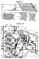
- FIG. 1 A preferred embodiment of this invention is illustrated in the accompanying drawings particularly showing a waste comminuting apparatus generally designated with the numeral 10 in Figs. 2 and 3 for receiving waste material 12 and for reducing waste material progressively to smaller and smaller sizes until a desired particulate size is obtained as illustrated in Fig. 1.
- the waste material illustrated in Fig. 1 is progessively reduced to smaller pieces 14a-e.
- the smaller pieces that have not been sufficiently reduced to the desired size are referred to as oversized smaller pieces.
- the apparatus 10 has a general frame 16 that may be self-supported or affixed to other apparatus such as the discharge of a thermal forming machine for receiving the waste material 12 directly from the thermal forming machine and reducing the material for reuse.
- the frame 16 generally includes a general enclosure 18 that includes a front wall 21, two side walls 22, 24, a back wall 26, a bottom wall 28 and a top wall 30.
- the top wall 30 has a material entrance 32 (Fig. 5) through which the waste material is fed into the apparatus.
- the scissor roll 34 is mounted on a shaft 38 that rotates about an upper axis 39 (Fig. 4).
- the scissor roll 36 is mounted on a shaft 40 that rotates about a lower axis 41 that is vertically positioned parallel with an verticaly below the axis 39.
- the axes 39, 41 are positioned so that the scissor rolls 34 and 36 have sufficient overlap to shear the material between the scissor rolls as the material passes between the rolls.
- Each of the shafts 38 and 40 are supported for rotation by respective bearings 42 (Fig. 2).
- Each of the shafts 38 and 40 have hexagonal cross-sectional profiles, providing angular surfaces 44.
- Each of the scissor rolls 34 and 36 include a plurality of scissor rings 46 in which each of the rings 46 has a circular outer peripheral surface 48 and an inner hexagonal bearing surface 50 (Fig. 5).
- the inner hexagonal bearing surface 50 is complementary to the profile of the shafts 38 and 40 and are engaged by the surfaces 44 so that the scissor rings 46 rotate in response to the rotation of the shafts 38, 40.
- Each of the scissor rings 46 include side surfaces 52 that form shearing edges 54 in conjunction with the circular outer peripheral surface 48.
- Each of the scissor rolls 34 and 36 further include a plurality of ring spacers 56.
- Each spacer 56 has a circular outer peripheral surface 58 and an inner circular surface 60 (Fig. 5).
- Each of the ring spacers 56 include side surfaces in which the width of the ring spacers is slightly greater than the width of the spacer rings 46.
- Each of the scissor rings 46 and the ring spacers 46 are alternately positioned on the shafts 38 and 40 so that a scissor ring 46 on one scissor roll opposes a corresponding ring spacer 56 on the other scissor roll creating a circular material cavity 64 (Fig. 2) between the adjacent scissor rings and outward of the intermediate ring spacer 56.
- the axes 39 and 41 are sufficiently spaced so that there is a slight overlap of approximately an eighth of an inch in the profile of the scissor rings so that as they are rotated the material is sheared by the shearing edges 54 as the profile of the scissor ring 46 moves into the circular material cavity 64 of the opposing ring spacer 56.
- the apparatus 10 further includes feeding means (Figs. 4 and 5) generally designated with the numeral 66 and includes a chute 68 that communicates with material entrance 32 for receiving the material and directing the material between the scissor rolls 34, 36.
- the chute 68 is defined, in part, by the front wall 20.
- the feeding means include teeth mounted on the scissor rolls 34 and 36 for directing material between scissor rolls 34 and 36.
- the feeding means includes, a tooth 70 mounted on each of the scissor rings 46 at angularly located positions about the periphery of the scissor rolls 34, 36 to progressively direct material between the rolls.
- each tooth 70 is evenly spaced about the axis of the scissor roll.
- Each tooth 70 is formed by a curved bar that is complementary to the peripheral surface 48 of the scissor ring. Each curved bar is mounted by releasable bolts to respective scissor ring 46. Each tooth 70 has a leading abutment surface 76 for engaging and directing material between the scissor rolls.
- the thickness of the curved bar is less than the depth of the material cavity 64 so that the curved bar passes through the respective material cavity 64 of the complementary ring spacer 56. The depth of the material cavity 64 accommodates the curved bar 72 so that there is no interference.
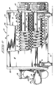
- the apparatus 10 further includes a concave screen plate 78 (Figs. 4 and 5) that is supported between the side walls 22 and 24 by plate supports 80.
- the concave plate has a radius of curvature with an axis that is parallel with the axes 39 and 41.
- the screen plate 78 includes a screen section 82 that has a large number of holes formed therein of a desired diameter defining the size of the undersize small pieces that pass through the screen. The pattern and size of the holes may vary considerably depending upon the waste material and the resultant size desired.
- the concave plate 78 further has an air baffle section 84 that is downstream of the screen section 82 for preventing or minimizing the flow of air countercurrent to the flow of the material.
- the apparatus 10 further includes a conveying means 86 for receiving the smaller pieces from the scissor rolls 34, 36 and for directing the smaller pieces over the screen section 82.
- the oversized small pieces are directed past the baffle section 84 and back to the feeding means 66 for recycling.
- the conveying means 86 includes a paddle wheel 88 (Fig. 4 and 5) that rotates on a shaft 90 about an axis 91 that is parallel with the axes 39 and 41.
- the axis 91 is coincident with the axis for the radius of curvature of the concave plate 78.
- the paddle whell 88 has a plurality of paddle blades 94 that extend across the wheel 88 between the side walls 22 and 24 for engaging the smaller pieces and moving the smaller pieces over the concave plate 78 permitting the undersized pieces to pass through the holes in the screen section 82 and for propelling the oversized particles with sufficient velocity to direct the oversized particles back to the feeding means 66 and more specifically into the chute 68 as illustrated in Fig. 5.
- each of the paddle blades 94 has a beveled outer surface 96 with an engaging front edge 97 for engaging the material and moving the material in a forward and upward direction along the screen section 82.
- the apparatus 10 further includes a guide 100 for guiding the smaller pieces 14 from the scissor rolls 34, 36 to the conveying means 86.
- the guide preferably is constructed of plates 102 and 104 that extend between the side walls 22 and 24 respectively, above and below the flow of the material from the scissor rolls 34 and 36 to direct the material from the rolls to the conveving means 86.
- the plates 102 and 104 diverge from each other to provide a progressively increasing throat for the flow of small pieces as they emerge from the scissor rolls 34, 36.
- Each of the plates 102 and 104 has a plurality of fingers 106 that are formed thereon and extend into the material cavity 64 of the respective scissor rolls 34 and 36 to clean and direct the smaller pieces from the material cavity 64 toward the conveying means 86.
- An air baffle 108 (Figs. 4 and 5) is mounted intermediate the scissor rolls 34 and 36 and paddle wheel 88 to act in conjunction with the plate 102 to prevent formation of an air current counter to the flow of the propelled smaller pieces between the scissor roller 34 and the paddle wheel 88.
- the air baffle 108 has a surface of sufficient size so that at least one of the paddle blades 94 is in registration with the air baffle 108 to prevent air current flow therebetween.
- the air baffle 108 and plate 102 in addition with the scissor roll 36 provides a recycle passageway 110 in communication with the paddle wheel 88 for permitting the propulsion of the oversized smaller pieces in a recycled path from the paddle wheel 88 back to the chute 68 for recycling and reducing the oversize smaller pieces even further.
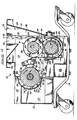
- the apparatus further includes a vacuum means generally designated with the numeral 112 and includes a vacuum blower 114 for generating a vacuum on the downstream side of the screen section 82 to create an air current 116 through the apparatus as illustrated in Fig. 4.
- the air current 116 is directed through the material entrance 32 and then between the scissor rolls 34, 36 through the material cavities 64.
- the air current 116 then is directed and bounded by the plates 102 and 104 to the paddle wheel 88.
- the vacuum causes the air current 116 to flow through the screen section 82 to draw the undersized smaller pieces 14 e therethrough to increase the efficiency of the separation on the screen section 82 and entrain the separated undersized smaller pieces 14 e in the air current.
- the undersize small pieces are drawn through the screen section 82 into a vacuum duct 118 that communicates with the vacuum blower 114 for directing the entrained smaller particles 14 e from the apparatus.
- the air current 116 is directed in the specific path indicated and is not permitted to flow countercurrent in the recycle passageway 110 which would hinder the recycle trajectory of the material, as the pieces are propelled by the paddle wheel 88 back to the chute 68.
- the air baffle section 84 and the air baffle 108 minimize the creation of the extraneous air currents that would interfere with the proper flow of material while still at the same time encouraging and permitting the efficient separation of the undersized smaller pieces from the oversized smaller pieces and in assisting in cleansing the apparatus from dust and other small particulate material.
- the apparatus further includes a drive means 120 that includes a motor 122 that is preferably mounted outside the enclosure 18 as illustrated in Fig. 3.
- the motor 122 is connected to a speed reduction transmission 124 which in turn is connected to the shaft 38.
- the speed reduction transmission 124 reduces the speed of the shaft 38 to a speed of less than 500 rpm and more preferably to a speed of less than 200 rpm.
- the motor 122 is driven at 1,800 rpm and the speed reduction transmission is a 10 to 1 reduction with the shaft 38 being driven at 180 rpm.
- the direction of the rotation of the shaft 38 is illustrated in Figs. 4 and 5 and is in an opposite direction to the rotation of the shaft 40.
- the shaft 38 (Fig.
- sprockets 126, 127 and 128 are operatively connected through sprockets 126, 127 and 128 via a chain 129 so as to coordinate the speeds of the shaft 38, 39 and 90.
- the sprockets 126 and 127 are the same size whereas the sprocket 128 is of a smaller size to rotate the paddle wheel 88 at a faster rpm than the rotation of the scissor rolls 34 and 36. It is important that the speed of the paddle wheel 88 be sufficient to move the oversized smaller particles at a sufficient velocity to propel the particles unsupported through the recycle passageway and over the scissor roll 34 back to the chute 68 to recycle the oversized smaller pieces.
- a chain tensioner 130 is provided to provide a constant tension on the chain 129. The tension may be adjusted as desired.
- waste material is directed into the apparatus through the material entrance 32 into the chute 68.
- the chute 68 in conjunction with the teeth 70 mounted on the scissor rolls 34, 36 engage and direct the material between the scissor rolls 34 and 36 wherein the material is sheared into smaller pieces in a progression as illustrated in Fig. 1.
- Material then is directed by the guide plates 102 and 104 from the scissor rolls 34, 36 to the screen section 82.
- the paddle wheel 88 engages the material and conveys the material over the screen section 82 to enable the undersized small particles to pass through the holes in the screen section 82 and into the duct 118.
- the air current created by the vacuum means 112 assist in the separation and in conveying of the material on the screen section 82.
- the vacuum means entrains the undersized smaller particles in the air current and conveys the particles from the apparatus.
- the oversized small pieces are then propelled by the paddle wheel upward over and forward through the recycle passageway 110 as illustrated in Fig. 5 in a trajectory sufficient to cause the recycled small pieces to pass into the chute 68.
- the material will be continuously recycled until the size of the material is reduced to an undersized small piece 14 e that pass through the screen. In this manner the apparatus is made very compact and provides a single shearing station that is very efficient to progressively reduce the size of the material to the desired particulate size dictated by the size of the holes in the screen section 82.
- the apparatus is operated at a very slow speed even though the apparatus is very efficient in reducing the material in an expeditious manner. Should any foreign material enter into the apparatus, it will not damage the equipment as the scissor rolls 34 and 36 can, if jammed, stop the motor 122 without damaging the rolls particularly the shearing edges 54. Additionally should any of the parts come lose they will not materially damage the apparatus as the scissor rolls and the paddle wheel for operating at relatively slow speeds and can be stopped by foreign material without damaging the parts. Very importantly the machine operates very quietly even though substantial shearing action is taking place. It is not unusual for the apparatus 10 to be operating at a decibel level far below what would normally be expected from a hammermill or the like. Thus the apparatus is very conducive to working conditions by employees even though there is a significant size reduction in the waste material. Other types of equipment require acoustical enclosures and noise reduction materials to protect the operators.
Landscapes
- Engineering & Computer Science (AREA)
- Food Science & Technology (AREA)
- Mechanical Engineering (AREA)
- Environmental & Geological Engineering (AREA)
- Combined Means For Separation Of Solids (AREA)
- Processing Of Solid Wastes (AREA)
- Crushing And Pulverization Processes (AREA)
Abstract
Description
- The invention relates to apparatus for comminuting waste material such as plastic sheet material of the kind as described in the preamble of claim 1.
- During the manufacture and forming of many products from plastic, significant amounts of plastic waste material is frequently produced. In the past, various types of hammermills have been utilized to receive the waste material and to reduce the waste material to a particle size sufficient so that material can be recycled and reused.
- Apparatus of the above mentioned kind are disclosed in US-A-4134556. The screen of these known apparatus consists of a screen drum, mounted for rotation about an horizontal axis. The scissor rolls are mounted for rotation within said screen drum and the oversized smaller pieces fall from the scissor rolls onto the bottom of said screen drum. They are conveyed upwards by the screen drum by means of partition blades thereof and fall at high level from these partition blades into the feeding means of the scissor rolls. These known apparatus are bulky, extremely noisy, and prone to substantial damage should the apparatus become jammed or receive foreign material that cannot be reduced by the apparatus.
- The objective of this invention is to overcome many of the problems and to provide a unique apparatus for comminuting waste material particularly plastic waste material produced during thermal forming or injection molding of plastic products. This is achieved with the provision of the apparatus as claimed in claim 1.
- Preferred embodiments are described in the sub-claims.
- Fig. 1 is a series of illustration views of the waste material and the reduction of the waste material into smaller particles as the matrial is progressively recycled and reduced to a desired particulate size;
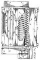
- Fig. 2 is a front view of the apparatus with a portion of the front wall cut away to illustrate a frontal view of a set of scissor rolls;
- Fig. 3 is a top view of the apparatus with a portion of enclosure cut away to illustrate a paddle wheel in conjunction with a scissor roll;
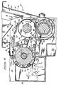
- Fig. 4 is a vertical cross-sectional view taken along line 4-4 in Fig. 3 illustrating the flow of air through the apparatus to assist in the progression of the material through the apparatus; and
- Fig. 5 is a cross-sectional view similar to Fig. 4 except showing the material flowing through the apparatus and being recycled to progressively reduce the material to the desired particulate size.
- A preferred embodiment of this invention is illustrated in the accompanying drawings particularly showing a waste comminuting apparatus generally designated with the
numeral 10 in Figs. 2 and 3 for receivingwaste material 12 and for reducing waste material progressively to smaller and smaller sizes until a desired particulate size is obtained as illustrated in Fig. 1. It should be noted that the apparatus is very compact even though the material is progressively reduced in size in several stages. The waste material illustrated in Fig. 1, is progessively reduced tosmaller pieces 14a-e. When the smaller pieces are finally reduced to the size of 14e, they are removed from the apparatus and are referred to as undersize smaller pieces. The smaller pieces that have not been sufficiently reduced to the desired size are referred to as oversized smaller pieces. - The
apparatus 10 has ageneral frame 16 that may be self-supported or affixed to other apparatus such as the discharge of a thermal forming machine for receiving thewaste material 12 directly from the thermal forming machine and reducing the material for reuse. Theframe 16 generally includes ageneral enclosure 18 that includes afront wall 21, twoside walls back wall 26, abottom wall 28 and atop wall 30. Thetop wall 30 has a material entrance 32 (Fig. 5) through which the waste material is fed into the apparatus. - Within the
enclosure 18 is mounted twoscissor rolls scissor rolls scissor roll 34 is mounted on ashaft 38 that rotates about an upper axis 39 (Fig. 4). Thescissor roll 36 is mounted on ashaft 40 that rotates about alower axis 41 that is vertically positioned parallel with an verticaly below theaxis 39. Theaxes shafts - Each of the
shafts angular surfaces 44. - Each of the
scissor rolls scissor rings 46 in which each of therings 46 has a circular outerperipheral surface 48 and an inner hexagonal bearing surface 50 (Fig. 5). The inner hexagonal bearingsurface 50 is complementary to the profile of theshafts surfaces 44 so that thescissor rings 46 rotate in response to the rotation of theshafts scissor rings 46 includeside surfaces 52 that formshearing edges 54 in conjunction with the circular outerperipheral surface 48. - Each of the scissor rolls 34 and 36 further include a plurality of
ring spacers 56. Eachspacer 56 has a circular outer peripheral surface 58 and an inner circular surface 60 (Fig. 5). Each of thering spacers 56 include side surfaces in which the width of the ring spacers is slightly greater than the width of thespacer rings 46. Each of thescissor rings 46 and thering spacers 46 are alternately positioned on theshafts scissor ring 46 on one scissor roll opposes acorresponding ring spacer 56 on the other scissor roll creating a circular material cavity 64 (Fig. 2) between the adjacent scissor rings and outward of theintermediate ring spacer 56. Once the material is cut or sheared, it is received in thematerial cavity 64 and passes between the rolls. Theaxes shearing edges 54 as the profile of thescissor ring 46 moves into thecircular material cavity 64 of theopposing ring spacer 56. - The
apparatus 10 further includes feeding means (Figs. 4 and 5) generally designated with thenumeral 66 and includes achute 68 that communicates withmaterial entrance 32 for receiving the material and directing the material between thescissor rolls chute 68 is defined, in part, by thefront wall 20. Additionally, the feeding means include teeth mounted on thescissor rolls scissor rolls tooth 70 mounted on each of thescissor rings 46 at angularly located positions about the periphery of thescissor rolls tooth 70 is evenly spaced about the axis of the scissor roll. Eachtooth 70 is formed by a curved bar that is complementary to theperipheral surface 48 of the scissor ring. Each curved bar is mounted by releasable bolts torespective scissor ring 46. Eachtooth 70 has a leadingabutment surface 76 for engaging and directing material between the scissor rolls. The thickness of the curved bar is less than the depth of thematerial cavity 64 so that the curved bar passes through therespective material cavity 64 of thecomplementary ring spacer 56. The depth of thematerial cavity 64 accommodates the curved bar 72 so that there is no interference. - The
apparatus 10 further includes a concave screen plate 78 (Figs. 4 and 5) that is supported between theside walls axes screen plate 78 includes ascreen section 82 that has a large number of holes formed therein of a desired diameter defining the size of the undersize small pieces that pass through the screen. The pattern and size of the holes may vary considerably depending upon the waste material and the resultant size desired. Theconcave plate 78 further has anair baffle section 84 that is downstream of thescreen section 82 for preventing or minimizing the flow of air countercurrent to the flow of the material. - The
apparatus 10 further includes a conveying means 86 for receiving the smaller pieces from thescissor rolls screen section 82. The oversized small pieces are directed past thebaffle section 84 and back to the feeding means 66 for recycling. Specifically in the preferred embodiment shown, the conveying means 86 includes a paddle wheel 88 (Fig. 4 and 5) that rotates on a shaft 90 about anaxis 91 that is parallel with theaxes axis 91 is coincident with the axis for the radius of curvature of theconcave plate 78. Thepaddle whell 88 has a plurality ofpaddle blades 94 that extend across thewheel 88 between theside walls concave plate 78 permitting the undersized pieces to pass through the holes in thescreen section 82 and for propelling the oversized particles with sufficient velocity to direct the oversized particles back to the feeding means 66 and more specifically into thechute 68 as illustrated in Fig. 5. There is a sufficient number ofblades 94 so that there is always one of theblades 94 in registration with theair baffle section 84 to prevent an air current from flowing between the paddle wheel and theair baffle section 84 countercurrent to the propulsion of the oversized pieces as they are being recycled from thescreen section 82 back to thechute 68 for further reduction in size by thescissor rolls paddle blades 94 has a beveledouter surface 96 with an engagingfront edge 97 for engaging the material and moving the material in a forward and upward direction along thescreen section 82. Preferably there is a tolerance of approximately one-eight inch between theengaging edge 97 and theconcave plate 78 to facilitate efficient separation of the undersized and oversized particles over the screen section and to prevent countercurrent air flows between theair baffle section 84. - The
apparatus 10 further includes aguide 100 for guiding thesmaller pieces 14 from thescissor rolls plates side walls scissor rolls conveving means 86. Theplates scissor rolls plates fingers 106 that are formed thereon and extend into thematerial cavity 64 of the respective scissor rolls 34 and 36 to clean and direct the smaller pieces from thematerial cavity 64 toward the conveyingmeans 86. - An air baffle 108 (Figs. 4 and 5) is mounted intermediate the scissor rolls 34 and 36 and
paddle wheel 88 to act in conjunction with theplate 102 to prevent formation of an air current counter to the flow of the propelled smaller pieces between thescissor roller 34 and thepaddle wheel 88. Theair baffle 108 has a surface of sufficient size so that at least one of thepaddle blades 94 is in registration with theair baffle 108 to prevent air current flow therebetween. Theair baffle 108 andplate 102 in addition with thescissor roll 36 provides arecycle passageway 110 in communication with thepaddle wheel 88 for permitting the propulsion of the oversized smaller pieces in a recycled path from thepaddle wheel 88 back to thechute 68 for recycling and reducing the oversize smaller pieces even further. - The apparatus further includes a vacuum means generally designated with the numeral 112 and includes a vacuum blower 114 for generating a vacuum on the downstream side of the
screen section 82 to create an air current 116 through the apparatus as illustrated in Fig. 4. The air current 116 is directed through thematerial entrance 32 and then between the scissor rolls 34, 36 through thematerial cavities 64. The air current 116 then is directed and bounded by theplates paddle wheel 88. The vacuum causes the air current 116 to flow through thescreen section 82 to draw the undersized smaller pieces 14e therethrough to increase the efficiency of the separation on thescreen section 82 and entrain the separated undersized smaller pieces 14e in the air current. The undersize small pieces are drawn through thescreen section 82 into avacuum duct 118 that communicates with the vacuum blower 114 for directing the entrained smaller particles 14e from the apparatus. - As previously noted, it is important that the air current 116 is directed in the specific path indicated and is not permitted to flow countercurrent in the
recycle passageway 110 which would hinder the recycle trajectory of the material, as the pieces are propelled by thepaddle wheel 88 back to thechute 68. Theair baffle section 84 and theair baffle 108 minimize the creation of the extraneous air currents that would interfere with the proper flow of material while still at the same time encouraging and permitting the efficient separation of the undersized smaller pieces from the oversized smaller pieces and in assisting in cleansing the apparatus from dust and other small particulate material. - The apparatus further includes a drive means 120 that includes a
motor 122 that is preferably mounted outside theenclosure 18 as illustrated in Fig. 3. Themotor 122 is connected to a speed reduction transmission 124 which in turn is connected to theshaft 38. Preferably the speed reduction transmission 124 reduces the speed of theshaft 38 to a speed of less than 500 rpm and more preferably to a speed of less than 200 rpm. In one specific example themotor 122 is driven at 1,800 rpm and the speed reduction transmission is a 10 to 1 reduction with theshaft 38 being driven at 180 rpm. The direction of the rotation of theshaft 38 is illustrated in Figs. 4 and 5 and is in an opposite direction to the rotation of theshaft 40. The shaft 38 (Fig. 6) is operatively connected throughsprockets chain 129 so as to coordinate the speeds of theshaft sprockets sprocket 128 is of a smaller size to rotate thepaddle wheel 88 at a faster rpm than the rotation of the scissor rolls 34 and 36. It is important that the speed of thepaddle wheel 88 be sufficient to move the oversized smaller particles at a sufficient velocity to propel the particles unsupported through the recycle passageway and over thescissor roll 34 back to thechute 68 to recycle the oversized smaller pieces. It has been found that for a particularsize paddle wheel 88 that a speed of 240 rpm was sufficient to provide a proper relationship between the peripheral velocities of scissor rolls 34 and 36 and the peripheral velocity of thepaddle wheel 88. A chain tensioner 130 is provided to provide a constant tension on thechain 129. The tension may be adjusted as desired. - During the operation of the apparatus, waste material is directed into the apparatus through the
material entrance 32 into thechute 68. Thechute 68 in conjunction with theteeth 70 mounted on the scissor rolls 34, 36 engage and direct the material between the scissor rolls 34 and 36 wherein the material is sheared into smaller pieces in a progression as illustrated in Fig. 1. Material then is directed by theguide plates screen section 82. Thepaddle wheel 88 engages the material and conveys the material over thescreen section 82 to enable the undersized small particles to pass through the holes in thescreen section 82 and into theduct 118. The air current created by the vacuum means 112 assist in the separation and in conveying of the material on thescreen section 82. Additionally, the vacuum means entrains the undersized smaller particles in the air current and conveys the particles from the apparatus. The oversized small pieces are then propelled by the paddle wheel upward over and forward through therecycle passageway 110 as illustrated in Fig. 5 in a trajectory sufficient to cause the recycled small pieces to pass into thechute 68. The material will be continuously recycled until the size of the material is reduced to an undersized small piece 14e that pass through the screen. In this manner the apparatus is made very compact and provides a single shearing station that is very efficient to progressively reduce the size of the material to the desired particulate size dictated by the size of the holes in thescreen section 82. - It should be further noted that the apparatus is operated at a very slow speed even though the apparatus is very efficient in reducing the material in an expeditious manner. Should any foreign material enter into the apparatus, it will not damage the equipment as the scissor rolls 34 and 36 can, if jammed, stop the
motor 122 without damaging the rolls particularly the shearing edges 54. Additionally should any of the parts come lose they will not materially damage the apparatus as the scissor rolls and the paddle wheel for operating at relatively slow speeds and can be stopped by foreign material without damaging the parts. Very importantly the machine operates very quietly even though substantial shearing action is taking place. It is not unusual for theapparatus 10 to be operating at a decibel level far below what would normally be expected from a hammermill or the like. Thus the apparatus is very conducive to working conditions by employees even though there is a significant size reduction in the waste material. Other types of equipment require acoustical enclosures and noise reduction materials to protect the operators. - In compliance with the statute, the invention has been described in language more or less specific as to structural features. It is to be understood, however, that the invention is not limited to the specific features shown, since the means and construction herein disclosed comprise a preferred form of putting the invention into effect. The invention is therefore, claimed in any of its forms or modifications within the proper scope of the appended claims, appropriately interpreted in accordance with the doctrine of equivalents.
Claims (12)
Priority Applications (1)
| Application Number | Priority Date | Filing Date | Title |
|---|---|---|---|
| AT87201032T ATE63481T1 (en) | 1986-06-13 | 1987-06-02 | APPARATUS FOR SHREDDING WASTE. |
Applications Claiming Priority (2)
| Application Number | Priority Date | Filing Date | Title |
|---|---|---|---|
| US06/874,151 US4687144A (en) | 1986-06-13 | 1986-06-13 | Apparatus for comminuting waste materials |
| US874151 | 1986-06-13 |
Publications (3)
| Publication Number | Publication Date |
|---|---|
| EP0249276A2 EP0249276A2 (en) | 1987-12-16 |
| EP0249276A3 EP0249276A3 (en) | 1988-11-23 |
| EP0249276B1 true EP0249276B1 (en) | 1991-05-15 |
Family
ID=25363091
Family Applications (1)
| Application Number | Title | Priority Date | Filing Date |
|---|---|---|---|
| EP87201032A Expired - Lifetime EP0249276B1 (en) | 1986-06-13 | 1987-06-02 | Apparatus for comminuting waste materials |
Country Status (4)
| Country | Link |
|---|---|
| US (1) | US4687144A (en) |
| EP (1) | EP0249276B1 (en) |
| AT (1) | ATE63481T1 (en) |
| DE (1) | DE3770051D1 (en) |
Families Citing this family (34)
| Publication number | Priority date | Publication date | Assignee | Title |
|---|---|---|---|---|
| US5076503A (en) * | 1989-07-12 | 1991-12-31 | Cook Robert L | Size reduction processing apparatus for solid material |
| DE4023710A1 (en) * | 1990-07-26 | 1992-01-30 | Werner Buerklin | DEVICE FOR SHREDDING FIBROUS OR GRANULAR-LIKE HEAVYWEAR AS MUELL |
| US5143307A (en) * | 1991-03-11 | 1992-09-01 | Lundquist Lynn C | Secondary cutter apparatus for plastic size reduction equipment |
| US5441160A (en) * | 1991-04-29 | 1995-08-15 | Environmental Products Corporation | Method of collecting densified commodities using a mobile multi-compartment commodity collection and storage assembly |
| WO1992020046A1 (en) * | 1991-04-29 | 1992-11-12 | Environmental Products Corporation | Multiple-use commodity collection and storage system |
| US5465822A (en) * | 1992-03-16 | 1995-11-14 | Environmental Products Corporation | Commodity densification assembly having a multiple path distribution device |
| US5630493A (en) * | 1992-03-16 | 1997-05-20 | Environmental Products Corporation | Acceptance assembly for a reverse vending machine |
| JPH07115722B2 (en) * | 1992-03-16 | 1995-12-13 | エンバイアロンメンタル プロダクツ コーポレイション | Equipment for collecting, densifying and storing goods |
| FI94071C (en) * | 1992-06-23 | 1995-07-10 | Mikko Yrjoelae | Apparatus for processing materials |
| US5419502A (en) * | 1993-04-14 | 1995-05-30 | Wood Technology, Inc. | Tub grinder systems and methods for comminuting waste wood |
| US5669559A (en) * | 1993-07-30 | 1997-09-23 | Bayer Aktiengesellschaft | Process for pulverising polyurethane, polyurea and/or polyurethane/polyurea materials in a roller mill |
| WO1995033566A1 (en) * | 1994-06-06 | 1995-12-14 | Irwin Research & Development Inc. | An improved apparatus for comminuting solid waste materials |
| US5836527A (en) * | 1994-06-06 | 1998-11-17 | Irwin Research & Development | Apparatus for comminuting solid waste materials |
| US5713525A (en) * | 1995-03-31 | 1998-02-03 | Wood Technology, Inc. | Horizontal comminuting machine particularly for recyclable heavy wood randomly carrying non-shatterable foreign pieces |
| AT409103B (en) * | 1996-03-01 | 2002-05-27 | Ain Engineering Kk | Device for recovering plastics material from industrial waste comprising articles made of cast plastic, films or sheets of plastic or the like |
| US6067886A (en) * | 1996-08-02 | 2000-05-30 | The Vision Limited Partnership | Machine trim press having counterbalance features |
| US5860607A (en) * | 1997-01-08 | 1999-01-19 | Irwin Research & Development, Inc. | Apparatus for comminuting waste materials having screw delivery features |
| US5893523A (en) * | 1997-06-13 | 1999-04-13 | Irwin Research & Development, Inc. | Apparatus for comminuting waste materials having feed roll delivery features |
| DE19809383A1 (en) * | 1998-03-05 | 1999-09-09 | Kronenberger | Bucket separator |
| GB2341563A (en) * | 1998-09-17 | 2000-03-22 | Airmat Systems Ltd | Disposal of waste sheet material |
| WO2001024996A1 (en) | 1999-09-30 | 2001-04-12 | Peterson Gregory J | Artificial firelog and firestarter chip producing apparatus and method and products produced therefrom |
| US6251147B1 (en) * | 1998-10-01 | 2001-06-26 | Gregory J. Peterson | Artifical firelog and firestarter chip producing apparatus and method and products produced therefrom |
| US6357680B1 (en) | 1999-06-16 | 2002-03-19 | Jere F. Irwin | Self-feeding comminuting apparatus having improved drive motor features |
| US6644570B1 (en) | 1999-10-15 | 2003-11-11 | Jere F. Irwin | Downstream pneumatic recirculation comminuting apparatus |
| US6435067B1 (en) | 2000-05-22 | 2002-08-20 | Jere F. Irwin | Apparatus and method for registering articles during a web processing operation |
| US6843156B1 (en) * | 2000-10-10 | 2005-01-18 | Jere F. Irwin | Apparatus for conveying, guiding, and locating a thermoformable web |
| US6644573B2 (en) | 2001-06-18 | 2003-11-11 | Jere F. Irwin | Comminuting apparatus and pneumatic recirculation systems for comminuting apparatus |
| US20050263633A1 (en) * | 2004-05-25 | 2005-12-01 | Vantrease Dale L | Serrated scissor ring, comminuting apparatus, and method |
| EP1874474A4 (en) * | 2005-03-01 | 2014-04-09 | Rodney Warwick Sharp | Improvements in and relating to drums for hogging apparatus |
| US7419110B2 (en) * | 2005-07-01 | 2008-09-02 | Irwin Jere F | Comminuting apparatus and material receiving duct for comminuting apparatus |
| US20080041998A1 (en) * | 2006-03-28 | 2008-02-21 | Gillis Terrence E | Material processor apparatus and method for recycling construction and demolition waste |
| CN105013794A (en) * | 2014-04-28 | 2015-11-04 | 际峰机械钣金股份有限公司 | Kitchen waste processing machine |
| US11065624B2 (en) * | 2019-07-03 | 2021-07-20 | Scott Equipment Company | Carton reducer/bag opener device |
| CN119175210B (en) * | 2024-11-26 | 2025-03-14 | 平定佳韵紫砂制造有限公司 | Purple sand fine screening device and application method thereof |
Family Cites Families (5)
| Publication number | Priority date | Publication date | Assignee | Title |
|---|---|---|---|---|
| FR2314654A1 (en) * | 1975-06-18 | 1977-01-14 | Beltran Robert | Vine pruning pulverising machine - has inclined telescopic pickup rods delivering to beater arms via cutter discs |
| US4052013A (en) * | 1976-03-08 | 1977-10-04 | Georgia-Pacific Corporation | Apparatus for shredding rubber tires and other scrap materials |
| EP0064596B1 (en) * | 1981-05-07 | 1986-07-02 | Colortronic Reinhard GmbH + Co.KG | Granulating mill for comminuting runners, moulded parts, blown hollow bodies, etc. |
| DE3312173C2 (en) * | 1983-04-02 | 1994-06-30 | Krug & Priester Ideal Werk | Cutting device of a device used for shredding and shredding paper sheets, documents and foils |
| FR2544629B1 (en) * | 1983-04-20 | 1986-01-31 | Clayton | LOW-SIZE RECOVERY PRODUCTS GRINDING MACHINE |
-
1986
- 1986-06-13 US US06/874,151 patent/US4687144A/en not_active Expired - Lifetime
-
1987
- 1987-06-02 EP EP87201032A patent/EP0249276B1/en not_active Expired - Lifetime
- 1987-06-02 AT AT87201032T patent/ATE63481T1/en active
- 1987-06-02 DE DE8787201032T patent/DE3770051D1/en not_active Expired - Fee Related
Also Published As
| Publication number | Publication date |
|---|---|
| EP0249276A3 (en) | 1988-11-23 |
| EP0249276A2 (en) | 1987-12-16 |
| DE3770051D1 (en) | 1991-06-20 |
| US4687144A (en) | 1987-08-18 |
| ATE63481T1 (en) | 1991-06-15 |
Similar Documents
| Publication | Publication Date | Title |
|---|---|---|
| US4687144A (en) | Apparatus for comminuting waste materials | |
| FI70166B (en) | ANORDINATION FOR THE PURPOSE OF LAW HASTIGHET AV FRAON EN MATERIALBANA AVSLITSAD REMS | |
| US4154407A (en) | Reducing drum for the extraction of cellulosic matters | |
| US3762256A (en) | Polymeric web shredding | |
| US5348162A (en) | Machine for processing goods, especially refuse, for sorting it | |
| US7048215B2 (en) | Comminuting apparatus having screen and access tray | |
| US20050263633A1 (en) | Serrated scissor ring, comminuting apparatus, and method | |
| US5893523A (en) | Apparatus for comminuting waste materials having feed roll delivery features | |
| US6644570B1 (en) | Downstream pneumatic recirculation comminuting apparatus | |
| US5836527A (en) | Apparatus for comminuting solid waste materials | |
| US5860607A (en) | Apparatus for comminuting waste materials having screw delivery features | |
| EP0455697B1 (en) | Machine for processing goods, especially refuse, for sorting it | |
| US6644573B2 (en) | Comminuting apparatus and pneumatic recirculation systems for comminuting apparatus | |
| CN220571536U (en) | A multifunctional composite filter rod cigarette cut tobacco recovery device | |
| US5042351A (en) | Feeding apparatus for a machine for feeding and cutting sheet materials | |
| CN105437344B (en) | A kind of broken plate sanding production line | |
| CA1280393C (en) | Apparatus for comminuting waste materials | |
| US7083132B2 (en) | Comminuting apparatus with multiple entrance openings | |
| JP2000070748A (en) | Circulating crusher | |
| US3589627A (en) | Reduction mill | |
| EP0273446A2 (en) | Shredding process and apparatus for carrying out said process | |
| WO1995033566A1 (en) | An improved apparatus for comminuting solid waste materials | |
| CN116099605A (en) | Recycling device for discarded indwelling needles | |
| CN219805131U (en) | Novel running groove device capable of processing flying shear head input of bar | |
| CN214556894U (en) | Stamping forming aluminum cover device that gathers materials |
Legal Events
| Date | Code | Title | Description |
|---|---|---|---|
| PUAI | Public reference made under article 153(3) epc to a published international application that has entered the european phase |
Free format text: ORIGINAL CODE: 0009012 |
|
| AK | Designated contracting states |
Kind code of ref document: A2 Designated state(s): AT BE CH DE FR GB IT LI NL SE |
|
| PUAL | Search report despatched |
Free format text: ORIGINAL CODE: 0009013 |
|
| AK | Designated contracting states |
Kind code of ref document: A3 Designated state(s): AT BE CH DE FR GB IT LI NL SE |
|
| 17P | Request for examination filed |
Effective date: 19890519 |
|
| 17Q | First examination report despatched |
Effective date: 19891113 |
|
| ITF | It: translation for a ep patent filed | ||
| GRAA | (expected) grant |
Free format text: ORIGINAL CODE: 0009210 |
|
| RAP3 | Party data changed (applicant data changed or rights of an application transferred) |
Owner name: IRWIN RESEARCH & DEVELOPMENT, INC. |
|
| AK | Designated contracting states |
Kind code of ref document: B1 Designated state(s): AT BE CH DE FR GB IT LI NL SE |
|
| REF | Corresponds to: |
Ref document number: 63481 Country of ref document: AT Date of ref document: 19910615 Kind code of ref document: T |
|
| REF | Corresponds to: |
Ref document number: 3770051 Country of ref document: DE Date of ref document: 19910620 |
|
| ET | Fr: translation filed | ||
| PLBE | No opposition filed within time limit |
Free format text: ORIGINAL CODE: 0009261 |
|
| STAA | Information on the status of an ep patent application or granted ep patent |
Free format text: STATUS: NO OPPOSITION FILED WITHIN TIME LIMIT |
|
| 26N | No opposition filed | ||
| EAL | Se: european patent in force in sweden |
Ref document number: 87201032.7 |
|
| PGFP | Annual fee paid to national office [announced via postgrant information from national office to epo] |
Ref country code: GB Payment date: 19970606 Year of fee payment: 11 |
|
| PGFP | Annual fee paid to national office [announced via postgrant information from national office to epo] |
Ref country code: SE Payment date: 19970625 Year of fee payment: 11 |
|
| PGFP | Annual fee paid to national office [announced via postgrant information from national office to epo] |
Ref country code: AT Payment date: 19970627 Year of fee payment: 11 |
|
| PGFP | Annual fee paid to national office [announced via postgrant information from national office to epo] |
Ref country code: NL Payment date: 19970630 Year of fee payment: 11 Ref country code: FR Payment date: 19970630 Year of fee payment: 11 Ref country code: DE Payment date: 19970630 Year of fee payment: 11 |
|
| PGFP | Annual fee paid to national office [announced via postgrant information from national office to epo] |
Ref country code: BE Payment date: 19970722 Year of fee payment: 11 |
|
| PGFP | Annual fee paid to national office [announced via postgrant information from national office to epo] |
Ref country code: CH Payment date: 19970901 Year of fee payment: 11 |
|
| PG25 | Lapsed in a contracting state [announced via postgrant information from national office to epo] |
Ref country code: GB Free format text: LAPSE BECAUSE OF NON-PAYMENT OF DUE FEES Effective date: 19980602 Ref country code: AT Free format text: LAPSE BECAUSE OF NON-PAYMENT OF DUE FEES Effective date: 19980602 |
|
| PG25 | Lapsed in a contracting state [announced via postgrant information from national office to epo] |
Ref country code: SE Free format text: LAPSE BECAUSE OF NON-PAYMENT OF DUE FEES Effective date: 19980603 |
|
| PG25 | Lapsed in a contracting state [announced via postgrant information from national office to epo] |
Ref country code: LI Free format text: LAPSE BECAUSE OF NON-PAYMENT OF DUE FEES Effective date: 19980630 Ref country code: CH Free format text: LAPSE BECAUSE OF NON-PAYMENT OF DUE FEES Effective date: 19980630 Ref country code: BE Free format text: LAPSE BECAUSE OF NON-PAYMENT OF DUE FEES Effective date: 19980630 |
|
| BERE | Be: lapsed |
Owner name: IRWIN RESEARCH & DEVELOPMENT INC. Effective date: 19980630 |
|
| PG25 | Lapsed in a contracting state [announced via postgrant information from national office to epo] |
Ref country code: NL Free format text: LAPSE BECAUSE OF NON-PAYMENT OF DUE FEES Effective date: 19990101 |
|
| GBPC | Gb: european patent ceased through non-payment of renewal fee |
Effective date: 19980602 |
|
| REG | Reference to a national code |
Ref country code: CH Ref legal event code: PL |
|
| PG25 | Lapsed in a contracting state [announced via postgrant information from national office to epo] |
Ref country code: FR Free format text: LAPSE BECAUSE OF NON-PAYMENT OF DUE FEES Effective date: 19990226 |
|
| EUG | Se: european patent has lapsed |
Ref document number: 87201032.7 |
|
| NLV4 | Nl: lapsed or anulled due to non-payment of the annual fee |
Effective date: 19990101 |
|
| PG25 | Lapsed in a contracting state [announced via postgrant information from national office to epo] |
Ref country code: DE Free format text: LAPSE BECAUSE OF NON-PAYMENT OF DUE FEES Effective date: 19990401 |
|
| REG | Reference to a national code |
Ref country code: FR Ref legal event code: ST |
|
| PG25 | Lapsed in a contracting state [announced via postgrant information from national office to epo] |
Ref country code: IT Free format text: LAPSE BECAUSE OF NON-PAYMENT OF DUE FEES;WARNING: LAPSES OF ITALIAN PATENTS WITH EFFECTIVE DATE BEFORE 2007 MAY HAVE OCCURRED AT ANY TIME BEFORE 2007. THE CORRECT EFFECTIVE DATE MAY BE DIFFERENT FROM THE ONE RECORDED. Effective date: 20050602 |