EP0248505B1 - Hydraulic power source, in particular for tilting the cab of a truck - Google Patents
Hydraulic power source, in particular for tilting the cab of a truck Download PDFInfo
- Publication number
- EP0248505B1 EP0248505B1 EP87201072A EP87201072A EP0248505B1 EP 0248505 B1 EP0248505 B1 EP 0248505B1 EP 87201072 A EP87201072 A EP 87201072A EP 87201072 A EP87201072 A EP 87201072A EP 0248505 B1 EP0248505 B1 EP 0248505B1
- Authority
- EP
- European Patent Office
- Prior art keywords
- pump
- reservoir
- suction
- pressure
- stator
- Prior art date
- Legal status (The legal status is an assumption and is not a legal conclusion. Google has not performed a legal analysis and makes no representation as to the accuracy of the status listed.)
- Expired - Lifetime
Links
- 239000012530 fluid Substances 0.000 claims description 15
- 230000001419 dependent effect Effects 0.000 claims description 3
- 230000006854 communication Effects 0.000 claims description 2
- 238000004891 communication Methods 0.000 claims description 2
- 238000006073 displacement reaction Methods 0.000 claims 4
- 230000002441 reversible effect Effects 0.000 claims 2
- 235000015115 caffè latte Nutrition 0.000 claims 1
- 238000010586 diagram Methods 0.000 description 5
- 230000000903 blocking effect Effects 0.000 description 1
Images



Classifications
-
- F—MECHANICAL ENGINEERING; LIGHTING; HEATING; WEAPONS; BLASTING
- F15—FLUID-PRESSURE ACTUATORS; HYDRAULICS OR PNEUMATICS IN GENERAL
- F15B—SYSTEMS ACTING BY MEANS OF FLUIDS IN GENERAL; FLUID-PRESSURE ACTUATORS, e.g. SERVOMOTORS; DETAILS OF FLUID-PRESSURE SYSTEMS, NOT OTHERWISE PROVIDED FOR
- F15B7/00—Systems in which the movement produced is definitely related to the output of a volumetric pump; Telemotors
- F15B7/005—With rotary or crank input
- F15B7/006—Rotary pump input
-
- B—PERFORMING OPERATIONS; TRANSPORTING
- B62—LAND VEHICLES FOR TRAVELLING OTHERWISE THAN ON RAILS
- B62D—MOTOR VEHICLES; TRAILERS
- B62D33/00—Superstructures for load-carrying vehicles
- B62D33/06—Drivers' cabs
- B62D33/063—Drivers' cabs movable from one position into at least one other position, e.g. tiltable, pivotable about a vertical axis, displaceable from one side of the vehicle to the other
- B62D33/067—Drivers' cabs movable from one position into at least one other position, e.g. tiltable, pivotable about a vertical axis, displaceable from one side of the vehicle to the other tiltable
Definitions
- the invention relates to a hydraulic power source of the type defined in the introductory part of either of the attached claims 1 and 2.
- the present invention aims at improving the above power source so as to increase its degree of compactness.
- suction shuttle valve used in claim 1 is to be understood as comprising two check valve members, each associated with one of said suction/pressure conduits and located each between the said connecting passage and the respective suction/pressure conduit, said check valve members being interconnected in such a manner that one of them is forced into the open position when the other is closed as a result of a pressure increase in the respective suction/pressure conduit.
- the special type of pump used in accordance with this aspect of the invention allows the use of much higher working pressures than with a gear pump, so that the size of the piston cilinder device may be reduced quite considerably.
- the type of pump used in the hydraulic power source according to the invention is well-known perse.
- a pump is disclosed in FR-A-2099846. It has not been proposed, so far, to use such a pump as a reversable rotary pump in an hydraulic power unit of the type above referred to.
- the pump used in accordance with this second aspect of the invention in fact comprises two super imposed pumps of the type according to the first inventive aspect.
- the advantage of using two super imposed pumps is to be seen in that no shuttle valve means are required to create a blocking of the connection betwen the pressure side and the reservoir.
- the numeral 1 designates a double-acting piston-cylinder device having an eyelet 1′ at the cylinder bottom for pivotal connection to the frame of a vehicle equipped with a tilting cabin, while the free end (not shown) of the piston rod 1 ⁇ is adapted to be pivotally connected to the tilting cabin.
- the drive unit 3 which is connected to the piston-cylinder device 1 through a common base 2, comprises a reservoir 4 for hydraulic fluid placed on said base 2, a rotary pump being housed in the reservoir and driven by a reversable electric motor 5.
- the electric leads to the electric current source of the vehicle are designated at 5a.
- the pump indicated at P in the hydraulic diagram of Fig. 2 will normally be a known type of gear pump. According to the invention, however, it is desired to reduce the diameter of the piston-cylinder device and as a consequence thereof the pump of Fig. 3 is proposed, which is of a type allowing operation at high pressures.
- the pump comprises a stator 6 fixedly supported at the base 2 and a rotor 7 mounted for rotation around said stator and coupled with the electric motor by shaft 5′.
- the rotor 7 there are four plungers 8 slidably mounted in radial bores, which plungers are, when the rotor is rotating, periodically swung outwardly and urged inwardly by a slide bearing ring 9 mounted excentrically around the rotor 7.
- the stator 6 has two rectangular recesses 10 located in the radial cross-sectional plane of the bores of the plungers 8 at two diametrically opposed sides of the stator. Dependent on the direction of rotation of the pump one recess will function as a pressure chamber and the other will function as a suction chamber.
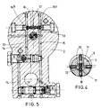
- Two axial conduits 11 are provided in the stator which are each connected to a recess 10 through a connecting passage 12 (vide fig. 4) and are on the other hand each connected, through a connecting passage 13, to a suction/pressure conduit 14 or 15 extending through the base 2 (vide Fig. 5).
- the conduits 14 and 15 are connected to connecting passage 17 leading to the reservoir 4 (vide Fig. 2, 3 and 5) via a suction shuttle valve 16.
- the conduit 14 is also connected to a passage 14′ leading to the cylinder space 18 above the piston of the piston cylinder device (vide Fig. 3) whereas the conduit 15 is in communi-cation with the space 19 under the piston (to the right in Fig. 3 and to the left in Fig. 2).
- conduits 14 and 15 are provided with pilot operated check valves A and B respectively, which are not directly related to the present invention and therefore have been omitted in the diagram of Fig. 2.
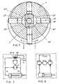
- the rotor comprises two superimposed groups of each four plungers, i.e. a lower group 8a and an upper group 8b at the level of each group the stator 6 has two diametrically opposed recesses 10a and 10b respectively.
- the right-hand space of the lower two recesses or spaces 10a is permanently connected to the reservoir, whereas the left-hand space of the upper two spaces 10b is permanently connected to the reservoir.
- the left-hand space of the lower two spaces 10a is connected, via a connecting bore 20a, to an axial passage 11a, which has a permanent connection, via valve A, with one end of the piston-cylinder device.
- the right-hand space of the upper two spaces 10b is, via a connecting bore 20b and valve B, permanently connected to the other end of the piston-cylinder device.
- the operation is as follows: Assuming that the pump is driven in the direction of the full arrow (anti-clockwise as seen in Fig. 7) the right-hand space 10b will function as a pressure chamber, from which hydraulic fluid will be pressed through axial passage 11b to the cylinder space on the piston rod side. In this case the left-hand space 10b is functioning, via connecting passage X, as a suction chamber. Via the open valve A hydraulic fluid may flow off from the cylinder space above the piston to the left-hand space 10a acting likewise as a suction chamber.
Landscapes
- Engineering & Computer Science (AREA)
- Mechanical Engineering (AREA)
- Physics & Mathematics (AREA)
- Fluid Mechanics (AREA)
- General Engineering & Computer Science (AREA)
- Chemical & Material Sciences (AREA)
- Combustion & Propulsion (AREA)
- Transportation (AREA)
- Reciprocating Pumps (AREA)
Description
- The invention relates to a hydraulic power source of the type defined in the introductory part of either of the attached
claims - An hydraulic power source of this type is disclosed in US-A-4551973. This well-known power source constitutes a rather compact power unit, wherein the reversable rotary pump is constituted by a conventional gear pump.
- The present invention aims at improving the above power source so as to increase its degree of compactness.
- In accordance with one aspect of the invention, this aim is achieved by the features mentioned in the characteristic clause of the attached
claim 1. In this connection the term "suction shuttle valve" used inclaim 1 is to be understood as comprising two check valve members, each associated with one of said suction/pressure conduits and located each between the said connecting passage and the respective suction/pressure conduit, said check valve members being interconnected in such a manner that one of them is forced into the open position when the other is closed as a result of a pressure increase in the respective suction/pressure conduit. - The special type of pump used in accordance with this aspect of the invention allows the use of much higher working pressures than with a gear pump, so that the size of the piston cilinder device may be reduced quite considerably.
- It is to be noted that the type of pump used in the hydraulic power source according to the invention is well-known perse. As an example such a pump is disclosed in FR-A-2099846. It has not been proposed, so far, to use such a pump as a reversable rotary pump in an hydraulic power unit of the type above referred to.
- In accordance with a second apsect of the invention the above aim is achieved by the features mentioned in the characteristic clause of appending
claim 2. - The pump used in accordance with this second aspect of the invention in fact comprises two super imposed pumps of the type according to the first inventive aspect. The advantage of using two super imposed pumps is to be seen in that no shuttle valve means are required to create a blocking of the connection betwen the pressure side and the reservoir. The invention will be hereinafter further explained by way of example with reference to the accompanying drawings.
- Fig. 1 shows a perspective view of a double-acting piston-cylinder device with built-on drive unit according to the invention;
- Fig. 2 shows a hydraulic diagram of the drive unit according to the invention, provided with a shuttle valve;
- Fig. 3 is a longitudinal section of the lower portion of the device of Fig. 1 and shows a pump adapted to be used in the diagram of Fig. 2 and suitable for supplying high pressures;
- Fig. 4 is a cross-sectional view on the line III-III through the pump portion of Fig. 3;
- Fig. 5 is a cross-sectional view on the line IV-IV of Fig. 3;
- Fig. 6 shows an axial section through the drive unit according to the invention in an embodiment having no shuttle valve;
- Fig. 7 is a cross-sectional view of the line VII-VII in Fig. 6 and
- Fig. 8 shows the hydraulic diagram of the device of Fig. 6.
- In Fig. 1 the
numeral 1 designates a double-acting piston-cylinder device having aneyelet 1′ at the cylinder bottom for pivotal connection to the frame of a vehicle equipped with a tilting cabin, while the free end (not shown) of thepiston rod 1˝ is adapted to be pivotally connected to the tilting cabin. - The
drive unit 3 which is connected to the piston-cylinder device 1 through acommon base 2, comprises areservoir 4 for hydraulic fluid placed on saidbase 2, a rotary pump being housed in the reservoir and driven by a reversableelectric motor 5. The electric leads to the electric current source of the vehicle are designated at 5a. - The pump indicated at P in the hydraulic diagram of Fig. 2 will normally be a known type of gear pump. According to the invention, however, it is desired to reduce the diameter of the piston-cylinder device and as a consequence thereof the pump of Fig. 3 is proposed, which is of a type allowing operation at high pressures.
- In the embodiment of Fig. 3 the pump comprises a
stator 6 fixedly supported at thebase 2 and arotor 7 mounted for rotation around said stator and coupled with the electric motor byshaft 5′. In therotor 7 there are fourplungers 8 slidably mounted in radial bores, which plungers are, when the rotor is rotating, periodically swung outwardly and urged inwardly by a slide bearingring 9 mounted excentrically around therotor 7. - The
stator 6 has tworectangular recesses 10 located in the radial cross-sectional plane of the bores of theplungers 8 at two diametrically opposed sides of the stator. Dependent on the direction of rotation of the pump one recess will function as a pressure chamber and the other will function as a suction chamber. Twoaxial conduits 11 are provided in the stator which are each connected to arecess 10 through a connecting passage 12 (vide fig. 4) and are on the other hand each connected, through a connectingpassage 13, to a suction/pressure conduit conduits passage 17 leading to the reservoir 4 (vide Fig. 2, 3 and 5) via asuction shuttle valve 16. Theconduit 14 is also connected to apassage 14′ leading to thecylinder space 18 above the piston of the piston cylinder device (vide Fig. 3) whereas theconduit 15 is in communi-cation with thespace 19 under the piston (to the right in Fig. 3 and to the left in Fig. 2). - In the embodiment of Fig. 3-5 the
conduits - The operation of the device described hereinabove is a follows.
- Assuming the direction of rotation of the pump, as seen in Fig. 4, is clockwise, the
space 10 on the right side will function as a pressure chamber, while thespace 10 on the left side will operate as a suction chamber, As a result of this theconduit 15 will be pressurized. - This causes the ball 16a of the suction shuttle valve 16 (Fig. 5) to be pressed on its seat, whereas the
ball 16b is released from its seat. Fluid is sucked into the suction chamber on the left side throughconduit 14 and theopen ball valve 16b. This fluid is then expelled through the pressure chamber on the right side and supplied under pressure throughconduit 15 to thespace 19 under the piston of thepiston cylinder device 1. At the same time fluid above the piston is allowed to flow off to the suction chamber and reservoir respectively via check valve A which has been opened by the pressure inconduit 15. In the assumed direction of rotation of the pump the piston of the piston cylinder device will thus be moved to the left (as seen in Fig. 3). It will be understood that a reversal of the direction of rotation will involve a change of functions of thespaces 10 so that fluid will then be supplied through left conduit 14 (Fig. 5) to the space above the piston, whereas the fluid under the piston is allowed to flow off to the suction chamber on the right (as seen in Fig. 4) and the reservoir respectively via the opened valve B and right-hand conduit 15. - In the embodiment of Fig. 6-8 the rotor comprises two superimposed groups of each four plungers, i.e. a
lower group 8a and anupper group 8b at the level of each group thestator 6 has two diametrically opposedrecesses 10a and 10b respectively. The right-hand space of the lower two recesses or spaces 10a is permanently connected to the reservoir, whereas the left-hand space of the upper twospaces 10b is permanently connected to the reservoir. The left-hand space of the lower two spaces 10a is connected, via a connecting bore 20a, to an axial passage 11a, which has a permanent connection, via valve A, with one end of the piston-cylinder device. The right-hand space of the upper twospaces 10b is, via a connectingbore 20b and valve B, permanently connected to the other end of the piston-cylinder device. - In this case the operation is as follows:
Assuming that the pump is driven in the direction of the full arrow (anti-clockwise as seen in Fig. 7) the right-hand space 10b will function as a pressure chamber, from which hydraulic fluid will be pressed through axial passage 11b to the cylinder space on the piston rod side. In this case the left-hand space 10b is functioning, via connecting passage X, as a suction chamber. Via the open valve A hydraulic fluid may flow off from the cylinder space above the piston to the left-hand space 10a acting likewise as a suction chamber. When the direction of rotation is reversed the left-hand space 10a will become active as a pressure chamber, whereas the right-hand space 10b′ will function as a suction chamber and collect hydraulic fluid from the cylinder space under the piston through the open valve B. An advantage of the second embodiment over the first one is be seen in that no suction shuttle valve is required.
Claims (2)
Applications Claiming Priority (2)
| Application Number | Priority Date | Filing Date | Title |
|---|---|---|---|
| NL8601475A NL8601475A (en) | 1986-06-06 | 1986-06-06 | DRIVE UNIT FOR A DOUBLE ACTING HYDRAULIC PISTON CYLINDER DEVICE. |
| NL8601475 | 1986-06-06 |
Publications (2)
| Publication Number | Publication Date |
|---|---|
| EP0248505A1 EP0248505A1 (en) | 1987-12-09 |
| EP0248505B1 true EP0248505B1 (en) | 1992-01-15 |
Family
ID=19848138
Family Applications (1)
| Application Number | Title | Priority Date | Filing Date |
|---|---|---|---|
| EP87201072A Expired - Lifetime EP0248505B1 (en) | 1986-06-06 | 1987-06-05 | Hydraulic power source, in particular for tilting the cab of a truck |
Country Status (3)
| Country | Link |
|---|---|
| EP (1) | EP0248505B1 (en) |
| DE (1) | DE3775991D1 (en) |
| NL (1) | NL8601475A (en) |
Families Citing this family (10)
| Publication number | Priority date | Publication date | Assignee | Title |
|---|---|---|---|---|
| DE4136286A1 (en) * | 1991-11-04 | 1993-05-06 | Mannesmann Rexroth Gmbh, 8770 Lohr, De | Hydraulic drive for movement control of incrementally variable camshaft adjustment - adjusts relative rotary angle between camshaft and drive wheel and uses pump and valve arrangement |
| NL9401190A (en) | 1994-07-20 | 1996-03-01 | Applied Power Inc | Hydraulic circuit. |
| NL1004341C2 (en) * | 1996-10-23 | 1998-04-24 | Applied Power Inc | Hydraulic tilting device for a cabin. |
| NL1012014C2 (en) * | 1999-05-10 | 2000-11-13 | Applied Power Inc | Vehicle with tilting cabin. |
| DE10306006B4 (en) * | 2003-02-12 | 2005-02-24 | Knapp, Jürgen Michael | hydraulic module |
| DE202010004921U1 (en) * | 2010-04-13 | 2011-09-01 | Faun Umwelttechnik Gmbh & Co. Kg | electric cylinders |
| CN104925146B (en) * | 2015-04-01 | 2017-12-29 | 安徽德鸿机件制造有限公司 | A kind of cab of heavy truck overturns integral electric hydraulic pump cylinder |
| CN104960584A (en) * | 2015-07-10 | 2015-10-07 | 实用动力(中国)工业有限公司 | Integrated hydraulic cab tilting power unit for heavy-load truck |
| CN116771739A (en) * | 2023-07-14 | 2023-09-19 | 长春一东汽车零部件制造有限责任公司 | Electric hydraulic cylinder |
| CN119062626B (en) * | 2024-11-06 | 2025-02-11 | 常州珂宸永馨精密机械有限公司 | Hydraulic valve and hydraulic system |
Citations (1)
| Publication number | Priority date | Publication date | Assignee | Title |
|---|---|---|---|---|
| US4551973A (en) * | 1982-10-28 | 1985-11-12 | Syntex (U.S.A.) Inc. | Hydraulic power source and valve therefor |
Family Cites Families (8)
| Publication number | Priority date | Publication date | Assignee | Title |
|---|---|---|---|---|
| US3064583A (en) * | 1957-03-29 | 1962-11-20 | Bendix Corp | Variable displacement pump |
| FR1290704A (en) * | 1961-06-01 | 1962-04-13 | Hydraulic cylinder control | |
| US3374625A (en) * | 1965-10-23 | 1968-03-26 | Whitfield M.P. Stuart | Valveless hydraulic actuating units |
| DE1650898A1 (en) * | 1968-01-13 | 1971-03-11 | Ver Baubeschlag Gretsch Co | Hydraulic actuation device, in particular for the operating rods on windows, doors or the like. |
| DE1601738A1 (en) * | 1968-01-13 | 1970-03-26 | Krupp Gmbh | Hydraulic signal box, especially crane luffing gear |
| GB1340875A (en) * | 1970-06-23 | 1973-12-19 | Lucas Industries Ltd | Rotary hydraulic machines with reciprocating pistons |
| DE2202825A1 (en) * | 1972-01-21 | 1973-07-26 | Lucas Industries Ltd | ROTARY HYDRAULIC MACHINE |
| DE2545637A1 (en) * | 1975-10-11 | 1977-04-21 | Alten K | Hydraulic drive with double acting cylinder - has back pressure valves for suction and pressure reversal of pump |
-
1986
- 1986-06-06 NL NL8601475A patent/NL8601475A/en not_active Application Discontinuation
-
1987
- 1987-06-05 DE DE8787201072T patent/DE3775991D1/en not_active Expired - Lifetime
- 1987-06-05 EP EP87201072A patent/EP0248505B1/en not_active Expired - Lifetime
Patent Citations (1)
| Publication number | Priority date | Publication date | Assignee | Title |
|---|---|---|---|---|
| US4551973A (en) * | 1982-10-28 | 1985-11-12 | Syntex (U.S.A.) Inc. | Hydraulic power source and valve therefor |
Also Published As
| Publication number | Publication date |
|---|---|
| DE3775991D1 (en) | 1992-02-27 |
| EP0248505A1 (en) | 1987-12-09 |
| NL8601475A (en) | 1988-01-04 |
Similar Documents
| Publication | Publication Date | Title |
|---|---|---|
| US4529362A (en) | Servo pump for hydraulic systems | |
| US4630441A (en) | Electrohydraulic actuator for aircraft control surfaces | |
| KR20170005489A (en) | Hydraulic apparatus | |
| US5224411A (en) | Hydraulic circuit for supplying at least one hydraulic motor incorporating "disengageable" pistons | |
| JPH0547753B2 (en) | ||
| JP5188444B2 (en) | Hydraulic drive device for work equipment | |
| US3800669A (en) | Control valve arrangement for a hydraulic drive | |
| US3332323A (en) | Rotary actuator | |
| EP1052127A1 (en) | Convertible top assembly with hydraulic actuating device | |
| EP0248505A1 (en) | Hydraulic power source, in particular for tilting the cab of a truck | |
| US5467596A (en) | Unitary electro-hydraulic rotary actuator for automotive convertible top | |
| CA2112357A1 (en) | Electrohydraulic Machine | |
| GB1505762A (en) | Axial piston machines | |
| EP1024284A3 (en) | Hydraulic pump control | |
| EP1496256B1 (en) | Pump control override for tandem pumps | |
| JPH01267367A (en) | Multi-throw piston pump | |
| US4193733A (en) | Hydraulic excavator machine having self-contained electrohydraulic power units | |
| US4551973A (en) | Hydraulic power source and valve therefor | |
| US5857381A (en) | Hydraulic operating device and gearbox provided with such an operating device | |
| US6578357B1 (en) | Regulating device for hydraulic working tools | |
| US2576359A (en) | Hoist control mechanism | |
| KR20000064677A (en) | Control valve for speed control of the first mover in the hydraulic system | |
| US20040000142A1 (en) | High-pressure and low-pressure selecting valve and swash-plate type hydraulic motor system | |
| CN215170574U (en) | Piston type hydraulic device | |
| JP3203487B2 (en) | Hydraulic pump / motor device |
Legal Events
| Date | Code | Title | Description |
|---|---|---|---|
| PUAI | Public reference made under article 153(3) epc to a published international application that has entered the european phase |
Free format text: ORIGINAL CODE: 0009012 |
|
| AK | Designated contracting states |
Kind code of ref document: A1 Designated state(s): DE FR GB IT NL SE |
|
| 17P | Request for examination filed |
Effective date: 19871209 |
|
| 17Q | First examination report despatched |
Effective date: 19880418 |
|
| GRAA | (expected) grant |
Free format text: ORIGINAL CODE: 0009210 |
|
| AK | Designated contracting states |
Kind code of ref document: B1 Designated state(s): DE FR GB IT NL SE |
|
| REF | Corresponds to: |
Ref document number: 3775991 Country of ref document: DE Date of ref document: 19920227 |
|
| ITF | It: translation for a ep patent filed | ||
| ET | Fr: translation filed | ||
| PLBI | Opposition filed |
Free format text: ORIGINAL CODE: 0009260 |
|
| 26 | Opposition filed |
Opponent name: ROBERT BOSCH GMBH Effective date: 19921015 |
|
| NLR1 | Nl: opposition has been filed with the epo |
Opponent name: ROBERT BOSCH GMBH |
|
| PLBN | Opposition rejected |
Free format text: ORIGINAL CODE: 0009273 |
|
| STAA | Information on the status of an ep patent application or granted ep patent |
Free format text: STATUS: OPPOSITION REJECTED |
|
| 27O | Opposition rejected |
Effective date: 19940820 |
|
| EAL | Se: european patent in force in sweden |
Ref document number: 87201072.3 |
|
| NLR2 | Nl: decision of opposition | ||
| REG | Reference to a national code |
Ref country code: GB Ref legal event code: IF02 |
|
| PGFP | Annual fee paid to national office [announced via postgrant information from national office to epo] |
Ref country code: GB Payment date: 20060530 Year of fee payment: 20 |
|
| PGFP | Annual fee paid to national office [announced via postgrant information from national office to epo] |
Ref country code: DE Payment date: 20060626 Year of fee payment: 20 |
|
| PGFP | Annual fee paid to national office [announced via postgrant information from national office to epo] |
Ref country code: SE Payment date: 20060629 Year of fee payment: 20 Ref country code: FR Payment date: 20060629 Year of fee payment: 20 |
|
| PGFP | Annual fee paid to national office [announced via postgrant information from national office to epo] |
Ref country code: NL Payment date: 20060630 Year of fee payment: 20 Ref country code: IT Payment date: 20060630 Year of fee payment: 20 |
|
| PG25 | Lapsed in a contracting state [announced via postgrant information from national office to epo] |
Ref country code: NL Free format text: LAPSE BECAUSE OF EXPIRATION OF PROTECTION Effective date: 20070605 |
|
| REG | Reference to a national code |
Ref country code: GB Ref legal event code: PE20 |
|
| NLV7 | Nl: ceased due to reaching the maximum lifetime of a patent |
Effective date: 20070605 |
|
| EUG | Se: european patent has lapsed | ||
| PG25 | Lapsed in a contracting state [announced via postgrant information from national office to epo] |
Ref country code: GB Free format text: LAPSE BECAUSE OF EXPIRATION OF PROTECTION Effective date: 20070604 |