EP0247255B1 - Pump liners and a method of cladding the same - Google Patents
Pump liners and a method of cladding the same Download PDFInfo
- Publication number
- EP0247255B1 EP0247255B1 EP86303990A EP86303990A EP0247255B1 EP 0247255 B1 EP0247255 B1 EP 0247255B1 EP 86303990 A EP86303990 A EP 86303990A EP 86303990 A EP86303990 A EP 86303990A EP 0247255 B1 EP0247255 B1 EP 0247255B1
- Authority
- EP
- European Patent Office
- Prior art keywords
- chamber
- layer
- metal
- powder
- particles
- Prior art date
- Legal status (The legal status is an assumption and is not a legal conclusion. Google has not performed a legal analysis and makes no representation as to the accuracy of the status listed.)
- Expired
Links
Images

Classifications
-
- B—PERFORMING OPERATIONS; TRANSPORTING
- B22—CASTING; POWDER METALLURGY
- B22F—WORKING METALLIC POWDER; MANUFACTURE OF ARTICLES FROM METALLIC POWDER; MAKING METALLIC POWDER; APPARATUS OR DEVICES SPECIALLY ADAPTED FOR METALLIC POWDER
- B22F7/00—Manufacture of composite layers, workpieces, or articles, comprising metallic powder, by sintering the powder, with or without compacting wherein at least one part is obtained by sintering or compression
- B22F7/06—Manufacture of composite layers, workpieces, or articles, comprising metallic powder, by sintering the powder, with or without compacting wherein at least one part is obtained by sintering or compression of composite workpieces or articles from parts, e.g. to form tipped tools
- B22F7/08—Manufacture of composite layers, workpieces, or articles, comprising metallic powder, by sintering the powder, with or without compacting wherein at least one part is obtained by sintering or compression of composite workpieces or articles from parts, e.g. to form tipped tools with one or more parts not made from powder
-
- C—CHEMISTRY; METALLURGY
- C22—METALLURGY; FERROUS OR NON-FERROUS ALLOYS; TREATMENT OF ALLOYS OR NON-FERROUS METALS
- C22C—ALLOYS
- C22C29/00—Alloys based on carbides, oxides, nitrides, borides, or silicides, e.g. cermets, or other metal compounds, e.g. oxynitrides, sulfides
- C22C29/02—Alloys based on carbides, oxides, nitrides, borides, or silicides, e.g. cermets, or other metal compounds, e.g. oxynitrides, sulfides based on carbides or carbonitrides
- C22C29/06—Alloys based on carbides, oxides, nitrides, borides, or silicides, e.g. cermets, or other metal compounds, e.g. oxynitrides, sulfides based on carbides or carbonitrides based on carbides, but not containing other metal compounds
- C22C29/067—Alloys based on carbides, oxides, nitrides, borides, or silicides, e.g. cermets, or other metal compounds, e.g. oxynitrides, sulfides based on carbides or carbonitrides based on carbides, but not containing other metal compounds comprising a particular metallic binder
Definitions
- This invention relates generally to cladding or coating cavities of metal objects, and more particularly to mud pump liner cavities.
- a cladding, or a coating that is more corrosion, oxidation and/or wear resistant than the metal object itself. This need may arise in some cases due to high temperatures created within the cavity, exposure to a corrosive or abrasive liquid, and/or to rubbing action of an internal machine member such as a piston.
- An example of such a metal object is the liners in mud pumps used in oil field drilling.
- a mud pump is a part of the oil or gas well drilling fluid circulating system, one of five major components of a rotary drilling operation. The other components are the drill string and bit, the hoisting system, the power plant and the blowout prevention system.
- Drilling fluid usually called the "mud"
- mud Drilling fluid, usually called the "mud”
- mud consists of a mixture of water, various special chemicals including corrosion inhibitors and solid particles such as Barite to increase its density.
- Such fluid is continuously circulated down the inside of the drill pipe, through the bottom of the bit and back up the annular space between the drill pipe and the hole.
- the driving force is provided by a mud pump.
- a mud pump liner is basically a heavy wall pipe section with one or two retaining rings at its outer diameter. It is the wear resistance of the inner surface that determines the liner service life. Consequently, the internal surface of the liner is desirably clad with a wear resistant material.
- the internal cladding layer is subjected to sliding wear by the rubber piston which can wear and cause metallic structure supporting the rubber to contact the liner cladding, thus accelerating the wear process.
- the cladding material is also subjected to corrosion from the drilling fluid, and metal fatigue caused by cyclic loading, especially at areas where the direction of the piston motion suddenly changes. Further, micro regions of cladding may experience sudden pressurization and depressurization. These operating conditions impose stringent metallurgical requirements on the cladding materials.
- An ideal cladding material should, therefore, possess high hardness and high resistance to corrosion, impact and metal fatigue. Such properties are desirably achieved by a uniform, fine grained microstructure, which has been the goal of pump liner makers of many
- the outer, heavy wall portions of the commercially available mud pump liners typically consist of either a carbon steel, or a low alloy steel; and the liner cladding is, in most cases, a cast sleeve of iron - 28% chromium alloy.
- the sleeve can be centrifugally cast into the steel pipe section or cast separately as a pipe, and shrink fitted into the outer pipe section, then machined to a smooth finish.
- These manufacturing procedures are lengthy and costly, while providing only a cast metal microstructure which is known to be chemically monuniform, since in castings the solidification process results in natural segregation of the elemental species contained in the alloy.
- the cladding thicknesses are kept undesirably large to allow casting processes to be used.
- the claddings within metallic objects other than pump liners can be similarly characterized and most likely be prone to the same deficiencies.
- Our earlier European Patent 0169 718 discloses a method of cladding the irregular exterior surface of a metal object, in which method a powder metal layer is applied on the surface and consolidated by pressurisation within a body of flowable pressure-transmitting material.
- a cladding layer made of powder metals consolidated to near 100% density and bonded to the outer steel shell appears to provide the most desirable metallurgical microstructure, due to its chemical uniformity and high ductility emanating from its grain size.
- Existing methods of application of such powder metal layers are grossly inadequate in that they either produce a porous, oxide contaminated layer which is only mechanically bonded to the outer shell as in sprayed coatings, or they are superficially and only mechanically bonded to the outer shell as in brazed-on coatings. For these, and other reasons, present powder metallurgy techniques for such products have not been considered adequate.
- One object of the invention to enable powder metal cladding of the internal cavity surface of metal liners and objects in a manner which overcomes the above problem and deficiencies.
- the invention provides various material combinations for the production of pump liners and internally clad pipe segments for use with oilfield mud pump fluids. There are many other products that can benefit from this processing technique.
- pressurization of the flowable particles referred to as grain is typically carried out by transmitting force to the grain along a primary axis, the layer extending about that axis and spaced therefrom, whereby force is transmitted by the grain away from the axis and against said layer.
- the die has a first chamber receiving the said object, and a second chamber containing grain communicating with grain in the cavity, pressurizing of the grain in the cavity being carried out by pressurizing the grain in the second chamber, as for example by transmitting pressure from the grain in the second chamber to only a medial portion of the grain in the first chamber everywhere spaced from said layer.
- the metal object is typically cylindrical, the layer being applied on an internal cylindrical surface of said object, the latter for example comprising a mud pump liner.
- an alloy steel mud pump liner 10 comprises an elongated tube 11 having an outer flange 12 on one end portion.
- the tube axis appears at 13, and the tube inner cylindrical surface at 14.
- Tube 11 may be considered to represent other metal objects having interior surfaces (as at 14) facing internal cavities 15.
- the tube or metal object to be clad Internal surfaces of the tube or metal object to be clad are first cleaned to remove any oxide layers, grease or dirt; then, using a slurry of the cladding metal powder and a suitable fugitive binder, these surfaces are coated with the slurry, the coating appearing at 16.
- the "green" coating is generally cylindrical, and has an outer surface 16 a containing the tube surface 14.
- the coating process can be accomplished by spraying, dipping in the slurry, brush, or spatula painting, or if the internal cavity is cylindrical, as is the case for pipes, the slurry may be centrifugally spread onto the internal surface by high speed spinning of the part.
- the thickness of the "green", weakly held together, powder metal-binder mixture can be controlled to some degree by controlling the total weight of the slurry used. Localized surfaces where cladding is not desired can be masked using adhesive tapes (see tape 17) which are removed after slurry coating is applied.
- the green coating is then dried at or near room temperature and heated to a temperature between 871°C and 1260°C (between 1600 °F and 2300 °F) where the coated metal powders are easily deformable under pressure.
- the furnace atmosphere should be either inert or reducing to prevent oxidation of the powder.
- Such a furnace is indicated at 18, and it may contain inert gas such as argon or nitrogen.
- the next step in the process is to place the liner containing the green now lightly sintered layer 11 a within a step die 19 where the liner fits into the large cavity (i.e first chamber 19) in the die as shown in the figure, and having inner cylindrical walls 19 a and 19 b .
- the die second chamber 20 throat diameter D1 should be equal to or smaller than the "green" internal diameter D2 of the mud pump liner 11 a . This assures relatively shearless pressing of the green powder metal cladding 11 a under largely lateral pressure during the pressurizing step.
- Chamber 20 has a bore 20 a .
- pressurization takes place in a press 21 after filling both the die and the pump liner cavities with a refractory powder 22 already at a temperature near or above the consolidation temperature of the cladding powder.
- the pressure from ram 23 is transmitted to the liner by the horizontal forces created within the refractory powder grains.
- the second chamber 20 is in axial alignment with the first chamber 19, the second chamber having a cross section less than the cross section of the first chamber, whereby pressure is transmitted from the grain 22 a in the second chamber to only a medial portion of the grain 22 b in the first chamber which is everywhere spaced from layer 11 a . Therefore, lateral pressurizing of the grain in the cavity 19 is effected by grain pressurized longitudinally in the second chamber, and no destructive shear is transmitted to layer 11 a .
- the cladding material consists of 98.5% by wt. powder mixed with 1.5% by weight cellulose acetate and acetone in an amount to establish sufficient fluidity to the mixture.
- This mixture is spun at 500 rpm to provide a thin (approximately 0.254 cm - 1/10th of an inch) green coating inside a 3.81 cm (1.5") long X 8.25 cm (3.25”) O.D. X 0.635 cms (0.25”) wall tube.
- the tubing is allowed to dry at room temperature overnight and heated to an elevated temperature for about 14 minutes, the furnace atmosphere being substantially hydrogen.
- the refractory grain which heated to 1260°C (2300°F) in a separate furnace is poured and the press ram allowed to pressurize the grain. After a peak pressure of 695 MN/m2 (45 tons per square inch) is reached for about 10 seconds, the pressurization cycle is considered complete and the pressure released. The die is then moved to a location where its contents can be emptied.
- a consolidated mixture of 40% Deloro 60 - 60% tungsten carbide powder (item 4 in Table 1) can be bonded to a steel tube at a temperature of 1037°C (1900°F) under 695 MN/m2 (45 tsi) pressure to produce a typical cladding microstructure at the steel tube cladding interface as shown in Figure 4.
- the process while remaining basically the same, may have some variations.
- the insulating material may be a ceramic, high density graphite or a metal which may be heated together with the part. If the insulating material is a metal, a non-bonding refractory powder parting compound may be applied on the insulating material.
- the die itself may be a vertically split die to ease the positioning of the part within it when the part shape is more complicated than a simple cylinder. Other minor variations of the process and the die may be utilized as well.
- Grains used to transmit pressure may have composition as referred to in the two U.S patents referred to above or other compositions that maybe used.
- the lined surface is defined by a mud pump liner having cylindrical shape, said surface at the inner side of the cylinder, the metal powder in said layer selected from the group essentially consisting of:
Landscapes
- Chemical & Material Sciences (AREA)
- Engineering & Computer Science (AREA)
- Materials Engineering (AREA)
- Mechanical Engineering (AREA)
- Composite Materials (AREA)
- Organic Chemistry (AREA)
- Metallurgy (AREA)
- Manufacturing & Machinery (AREA)
- Powder Metallurgy (AREA)
- Other Surface Treatments For Metallic Materials (AREA)
- Electrical Discharge Machining, Electrochemical Machining, And Combined Machining (AREA)
- Laminated Bodies (AREA)
- Details Of Reciprocating Pumps (AREA)
- Pistons, Piston Rings, And Cylinders (AREA)
Abstract
Description
- This invention relates generally to cladding or coating cavities of metal objects, and more particularly to mud pump liner cavities.
- Internal cavities of metal objects frequently require a cladding, or a coating, that is more corrosion, oxidation and/or wear resistant than the metal object itself. This need may arise in some cases due to high temperatures created within the cavity, exposure to a corrosive or abrasive liquid, and/or to rubbing action of an internal machine member such as a piston. An example of such a metal object is the liners in mud pumps used in oil field drilling. A mud pump is a part of the oil or gas well drilling fluid circulating system, one of five major components of a rotary drilling operation. The other components are the drill string and bit, the hoisting system, the power plant and the blowout prevention system.
- Drilling fluid, usually called the "mud", in most cases consists of a mixture of water, various special chemicals including corrosion inhibitors and solid particles such as Barite to increase its density. Such fluid is continuously circulated down the inside of the drill pipe, through the bottom of the bit and back up the annular space between the drill pipe and the hole. The driving force is provided by a mud pump.
- A mud pump liner is basically a heavy wall pipe section with one or two retaining rings at its outer diameter. It is the wear resistance of the inner surface that determines the liner service life. Consequently, the internal surface of the liner is desirably clad with a wear resistant material. The internal cladding layer is subjected to sliding wear by the rubber piston which can wear and cause metallic structure supporting the rubber to contact the liner cladding, thus accelerating the wear process. The cladding material is also subjected to corrosion from the drilling fluid, and metal fatigue caused by cyclic loading, especially at areas where the direction of the piston motion suddenly changes. Further, micro regions of cladding may experience sudden pressurization and depressurization. These operating conditions impose stringent metallurgical requirements on the cladding materials. An ideal cladding material should, therefore, possess high hardness and high resistance to corrosion, impact and metal fatigue. Such properties are desirably achieved by a uniform, fine grained microstructure, which has been the goal of pump liner makers of many years.
- The outer, heavy wall portions of the commercially available mud pump liners typically consist of either a carbon steel, or a low alloy steel; and the liner cladding is, in most cases, a cast sleeve of iron - 28% chromium alloy. The sleeve can be centrifugally cast into the steel pipe section or cast separately as a pipe, and shrink fitted into the outer pipe section, then machined to a smooth finish. These manufacturing procedures are lengthy and costly, while providing only a cast metal microstructure which is known to be chemically monuniform, since in castings the solidification process results in natural segregation of the elemental species contained in the alloy. Furthermore, the cladding thicknesses are kept undesirably large to allow casting processes to be used. The claddings within metallic objects other than pump liners can be similarly characterized and most likely be prone to the same deficiencies.
- Our earlier European Patent 0169 718 discloses a method of cladding the irregular exterior surface of a metal object, in which method a powder metal layer is applied on the surface and consolidated by pressurisation within a body of flowable pressure-transmitting material.
- A cladding layer made of powder metals consolidated to near 100% density and bonded to the outer steel shell appears to provide the most desirable metallurgical microstructure, due to its chemical uniformity and high ductility emanating from its grain size. Existing methods of application of such powder metal layers, however, are grossly inadequate in that they either produce a porous, oxide contaminated layer which is only mechanically bonded to the outer shell as in sprayed coatings, or they are superficially and only mechanically bonded to the outer shell as in brazed-on coatings. For these, and other reasons, present powder metallurgy techniques for such products have not been considered adequate.
- One object of the invention to enable powder metal cladding of the internal cavity surface of metal liners and objects in a manner which overcomes the above problem and deficiencies. In addition, the invention provides various material combinations for the production of pump liners and internally clad pipe segments for use with oilfield mud pump fluids. There are many other products that can benefit from this processing technique.
- In accordance with the invention we now propose a method of cladding an internal cavity surface of a metal object, which includes the steps:
- a) applying a powder metal layer on said internal cavity surface, the metal powder including a metal compound selected from metal oxide or oxides, borides or carbides,
- b) introducing the metal object having said powder metal layer on said internal cavity surface into a first chamber of a die and applying pressure-transmitting and flowable particles (grain) into contact with said layer within said chamber said die having a second chamber containing particles and communicating with said first chamber, the second chamber having a cross-section less than the cross-section of the first chamber, and
- c) applying a force to the particles in said second chamber so as to cause the particles in said first chamber to transmit sufficient pressure to consolidate the powder metal layer, said powder metal layer being disposed about and spaced from the axis along which said force is applied whereby force is transmitted along said axis by the particles in said second chamber and is transmitted away from said axis and against said metal powder layer by the particles in said first chamber.
- As will appear, pressurization of the flowable particles referred to as grain is typically carried out by transmitting force to the grain along a primary axis, the layer extending about that axis and spaced therefrom, whereby force is transmitted by the grain away from the axis and against said layer. The die has a first chamber receiving the said object, and a second chamber containing grain communicating with grain in the cavity, pressurizing of the grain in the cavity being carried out by pressurizing the grain in the second chamber, as for example by transmitting pressure from the grain in the second chamber to only a medial portion of the grain in the first chamber everywhere spaced from said layer. Further, the metal object is typically cylindrical, the layer being applied on an internal cylindrical surface of said object, the latter for example comprising a mud pump liner.
- These and other objects and advantages of the invention, as well as the details of an illustrative embodiment, will be more fully understood from the following description and drawings, in which:
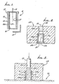
- Fig. 1 is a vertical section showing a mud pump liner;
- Fig. 2 is a vertical section showing a "green" coated mud pump liner placed in a double chamber die;
- Fig. 3 is similar to Fig. 2, but shows hot grain filled into the die and liner cavity, and pressurized; and
- Fig. 4 is a magnified section taken through the wall of a steel tube clad in accordance with the invention.
- Referring first to Fig. 1, an alloy steel
mud pump liner 10 comprises anelongated tube 11 having anouter flange 12 on one end portion. The tube axis appears at 13, and the tube inner cylindrical surface at 14. Tube 11 may be considered to represent other metal objects having interior surfaces (as at 14) facinginternal cavities 15. - Internal surfaces of the tube or metal object to be clad are first cleaned to remove any oxide layers, grease or dirt; then, using a slurry of the cladding metal powder and a suitable fugitive binder, these surfaces are coated with the slurry, the coating appearing at 16. As shown, the "green" coating is generally cylindrical, and has an outer surface 16a containing the
tube surface 14. The coating process can be accomplished by spraying, dipping in the slurry, brush, or spatula painting, or if the internal cavity is cylindrical, as is the case for pipes, the slurry may be centrifugally spread onto the internal surface by high speed spinning of the part. The thickness of the "green", weakly held together, powder metal-binder mixture can be controlled to some degree by controlling the total weight of the slurry used. Localized surfaces where cladding is not desired can be masked using adhesive tapes (see tape 17) which are removed after slurry coating is applied. The green coating is then dried at or near room temperature and heated to a temperature between 871°C and 1260°C (between 1600°F and 2300°F) where the coated metal powders are easily deformable under pressure. For most materials the furnace atmosphere should be either inert or reducing to prevent oxidation of the powder. Such a furnace is indicated at 18, and it may contain inert gas such as argon or nitrogen. - Referring to Figure 2, the next step in the process is to place the liner containing the green now lightly sintered layer 11a within a
step die 19 where the liner fits into the large cavity (i.e first chamber 19) in the die as shown in the figure, and having innercylindrical walls 19a and 19b. The diesecond chamber 20 throat diameter D₁ should be equal to or smaller than the "green" internal diameter D₂ of the mud pump liner 11a. This assures relatively shearless pressing of the green powder metal cladding 11a under largely lateral pressure during the pressurizing step.Chamber 20 has abore 20a. - As seen in Fig. 3, pressurization takes place in a
press 21 after filling both the die and the pump liner cavities with arefractory powder 22 already at a temperature near or above the consolidation temperature of the cladding powder. The pressure fromram 23 is transmitted to the liner by the horizontal forces created within the refractory powder grains. In this regard, thesecond chamber 20 is in axial alignment with thefirst chamber 19, the second chamber having a cross section less than the cross section of the first chamber, whereby pressure is transmitted from the grain 22a in the second chamber to only a medial portion of thegrain 22b in the first chamber which is everywhere spaced from layer 11a. Therefore, lateral pressurizing of the grain in thecavity 19 is effected by grain pressurized longitudinally in the second chamber, and no destructive shear is transmitted to layer 11a. - Consolidation of powder metal into substantially solid objects through the use of refractory particles (grain) has been disclosed in previous U.S patents No. 3,356,496 and No. 3,689,259 by R W Hailey. This invention, therefore, can be regarded as am improvement over those of the two patents, the invention providing a novel die design and a unique provision for horizontal pressurization transformed from a vertically applied load. The critical factor which prevents the powder cladding layer from being stripped (due to shear forces created when a vertically applied force is directly transmitted by a refractory bed of grain) is the die shape which moves the "shear" region away from the cladding.
- A number of experiments using steel tube segments measuring 3.81 cms (1.5 inches) long having 5.075 or 8.25 cms (2 or 3.25 inches) O.D's and 0.635 cms (0.25 inch) wall thickness were conducted to establish and verify the above described process. The objective was to clad the tubes with metal powder without distorting the tubes in any way. This was accomplished utilizing the die configuration shown in Figures 2 and 3.
- In a typical procedure the cladding material consists of 98.5% by wt. powder mixed with 1.5% by weight cellulose acetate and acetone in an amount to establish sufficient fluidity to the mixture. This mixture is spun at 500 rpm to provide a thin (approximately 0.254 cm - 1/10th of an inch) green coating inside a 3.81 cm (1.5") long X 8.25 cm (3.25") O.D. X 0.635 cms (0.25") wall tube. The tubing is allowed to dry at room temperature overnight and heated to an elevated temperature for about 14 minutes, the furnace atmosphere being substantially hydrogen. Immediately after the tube is placed in the die cavity, the refractory grain which heated to 1260°C (2300°F) in a separate furnace is poured and the press ram allowed to pressurize the grain. After a peak pressure of 695 MN/m² (45 tons per square inch) is reached for about 10 seconds, the pressurization cycle is considered complete and the pressure released. The die is then moved to a location where its contents can be emptied.
- In a modified procedure a furnace atmosphere of 100% nitrogen can be used instead of hydrogen.
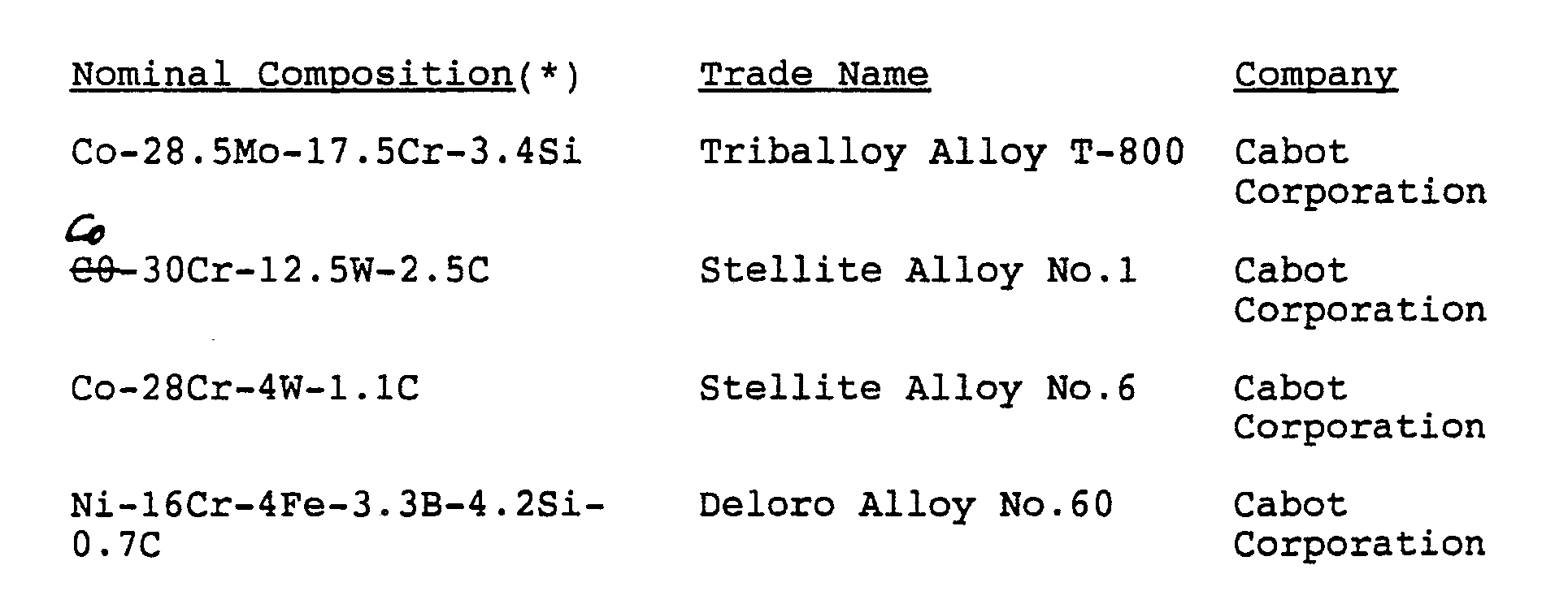
- A consolidated mixture of 40% Deloro 60 - 60% tungsten carbide powder (item 4 in Table 1) can be bonded to a steel tube at a temperature of 1037°C (1900°F) under 695 MN/m² (45 tsi) pressure to produce a typical cladding microstructure at the steel tube cladding interface as shown in Figure 4.
- Other applications utilizing various cladding materials to clad internal cavities of other metal objects such as valves, tubes, rock bits, etc can be accomplished as well.
- The process, while remaining basically the same, may have some variations. For example, there may be an insulating material positioned between the part (the pump liner in Figure 2) and the die to reduce heat loss before pressing.
- The insulating material may be a ceramic, high density graphite or a metal which may be heated together with the part. If the insulating material is a metal, a non-bonding refractory powder parting compound may be applied on the insulating material. In addition, the die itself may be a vertically split die to ease the positioning of the part within it when the part shape is more complicated than a simple cylinder. Other minor variations of the process and the die may be utilized as well.
- Grains used to transmit pressure may have composition as referred to in the two U.S patents referred to above or other compositions that maybe used.
-
Preferably, the lined surface is defined by a mud pump liner having cylindrical shape, said surface at the inner side of the cylinder, the metal powder in said layer selected from the group essentially consisting of: - a) Co-Cr-W-C
- b) Co-Mo-Cr-Si
- c) Ni-Cr-Fe-Si-B
- d) Ni-Mn-Si-Cu-B
- e) Ni-Co-Cr-Si-Fe-B
- f) Fe-Cr-Co-Ni-Si-C
- g) Cu-Mn-Ni
- a) Co-Cr-W-C
- b) Ni-Cr-Fe-Si-B
- c) Cu-Mn-Ni
- d) Ni-Co-Cr-Fe-Si-B
- e) Fe-Cr-Co-Ni-Si-C--
--Further, said layer may consist essentially of a mixture of 30 to 90% by weight tungsten carbide and remaining metal alloy powder selected from the group consisting of:
Claims (8)
- A method of cladding an internal cavity surface of a metal object (10), which includes the steps:a) applying a powder metal layer (11a) on said internal cavity surface, the metal powder including a metal compound selected from metal oxide or oxides, borides or carbides,b) introducing the metal object having said powder metal layer on said internal cavity surface into a first chamber (19) of a die (119) and applying pressure-transmitting and flowable particles (22) (grain) into contact with said layer within said chamber said die having a second chamber (20) containing particles and communicating with said first chamber, the second chamber (20) having a cross-section less than the cross-section of the first chamber (19), andc) applying a force to the particles in said second chamber so as to cause the particles in said first chamber to transmit sufficient pressure to consolidate the powder metal layer, said powder metal layer being disposed about and spaced from the axis (13) along which said force is applied whereby force is transmitted along said axis by the particles in said second chamber and is transmitted away from said axis and against said metal powder layer by the particles in said first chamber.
- A method according to claim 1 wherein said pressure is transmitted to only a medial portion of the particles (22) in the first chamber (19) everywhere spaced from said layer (11a).
- A method according to claim 1 or claim 2 wherein said object (10) is cylindrical and said a) step is carried out to apply said layer (11a) on an internal generally cylindrical surface of said object.
- A method according to claim 3 wherein said object (10) is a mud pump liner.
- A method according to any preceding claim wherein said layer (11a), as applied to said surface includes at least one of the compositions set forth in the following table, admixed with a minor amount of a fugitive organic binder:
TABLE Nominal Compositions Co-28.5Mo-17.5Cr-3.4Si Co-30Cr-12.5W-2.5C Co-28Cr-4W-1.1C Ni-16Cr-4Fe-3.3B-4.2Si-0.7C, plus up to 92% tungsten carbide Fe-35Cr-12Co-10Ni-5Si-2C, plus up to 92% tungsten carbide Cu-37Mn-10Ni-0.5La, plus Ni-19Mn-6Si-0.5B-4Cu-0.03 rare earth, plus up to 92% tungsten carbide Ni-13Cr-20Co-2.3B-4Si-4Fe, plus up to 92% tungsten carbide. - A method according to claim 5 wherein said mixture includes at least about 97% by weight of said composition, and at least about 1.0% by weight of said binder selected from the group consisting of cellulose acetate and hydrocarbon solvent.
- A method according to any preceding claim wherein said layer thickness is between 1.59 mm and 3.18 mm (1/16 inch and 1/8 inch), when said pressurisation is effected.
- A method according to any of claims 1 to 4 wherein in addition to said metal compound, the powder in said layer (11a) includes powder selected from the group consisting of:a) Co-Cr-W-Cb) Co-Mo-Cr-Sic) Ni-Cr-Fe-Si-Bd) Ni-Mn-Si-Cu-Be) Ni-Co-Cr-Si-Fe-Bf) Fe-Cr-Co-Ni-Si-Cg) Cu-Mn-Ni.
Priority Applications (2)
| Application Number | Priority Date | Filing Date | Title |
|---|---|---|---|
| AT86303990T ATE70475T1 (en) | 1985-01-07 | 1986-05-27 | JACKET FOR PUMP AND METHOD FOR ITS MANUFACTURE. |
| DE8686303990T DE3683044D1 (en) | 1985-01-07 | 1986-05-27 | COVER FOR PUMP AND METHOD FOR THE PRODUCTION THEREOF. |
Applications Claiming Priority (1)
| Application Number | Priority Date | Filing Date | Title |
|---|---|---|---|
| US06/689,312 US4603062A (en) | 1985-01-07 | 1985-01-07 | Pump liners and a method of cladding the same |
Publications (2)
| Publication Number | Publication Date |
|---|---|
| EP0247255A1 EP0247255A1 (en) | 1987-12-02 |
| EP0247255B1 true EP0247255B1 (en) | 1991-12-18 |
Family
ID=24767910
Family Applications (1)
| Application Number | Title | Priority Date | Filing Date |
|---|---|---|---|
| EP86303990A Expired EP0247255B1 (en) | 1985-01-07 | 1986-05-27 | Pump liners and a method of cladding the same |
Country Status (7)
| Country | Link |
|---|---|
| US (3) | US4603062A (en) |
| EP (1) | EP0247255B1 (en) |
| JP (1) | JPS62294105A (en) |
| AT (1) | ATE70475T1 (en) |
| AU (1) | AU590884B2 (en) |
| CA (2) | CA1235026A (en) |
| DE (1) | DE3683044D1 (en) |
Families Citing this family (28)
| Publication number | Priority date | Publication date | Assignee | Title |
|---|---|---|---|---|
| US4603062A (en) * | 1985-01-07 | 1986-07-29 | Cdp, Ltd. | Pump liners and a method of cladding the same |
| US4919013A (en) * | 1988-09-14 | 1990-04-24 | Eastman Christensen Company | Preformed elements for a rotary drill bit |
| US4933140A (en) * | 1988-11-17 | 1990-06-12 | Ceracon, Inc. | Electrical heating of graphite grain employed in consolidation of objects |
| US4853178A (en) * | 1988-11-17 | 1989-08-01 | Ceracon, Inc. | Electrical heating of graphite grain employed in consolidation of objects |
| JP2587872B2 (en) * | 1988-12-19 | 1997-03-05 | 住友金属鉱山株式会社 | Method for producing soft magnetic sintered body of Fe-Si alloy |
| US5294382A (en) * | 1988-12-20 | 1994-03-15 | Superior Graphite Co. | Method for control of resistivity in electroconsolidation of a preformed particulate workpiece |
| US4915605A (en) * | 1989-05-11 | 1990-04-10 | Ceracon, Inc. | Method of consolidation of powder aluminum and aluminum alloys |
| US5324168A (en) * | 1993-05-13 | 1994-06-28 | Eastman Kodak Company | Use of stellite to prevent silver plateout |
| ES2136921T3 (en) * | 1995-07-20 | 1999-12-01 | Dana Corp | METHOD FOR THE MANUFACTURE OF A CYLINDER SHIRT FROM AN INTERNAL COMBUSTION ENGINE. |
| US5617773A (en) * | 1995-11-07 | 1997-04-08 | Craft; Alan | Liner for use in corrosive and abrasive fluid pump and method of making same |
| CN2256043Y (en) * | 1995-12-15 | 1997-06-11 | 王德庆 | Long service life oil sucking pump with ceramic inlaid cylinder body |
| US6230610B1 (en) * | 1999-06-11 | 2001-05-15 | Utex Industries, Inc. | Pump liner |
| US6463843B2 (en) | 1999-06-11 | 2002-10-15 | Fredrick B. Pippert | Pump liner |
| US6675699B1 (en) | 2000-09-25 | 2004-01-13 | Utex Industries, Inc. | Composite components for use in pumps |
| DE10333152B3 (en) * | 2003-07-22 | 2005-01-20 | A. Raymond & Cie | Coating adhesion surfaces with a melt adhesive, comprises applying a mixed adhesive in powder form and then pressing to generate heat |
| DE102004039356B4 (en) * | 2004-08-12 | 2007-03-08 | Schmidt + Clemens Gmbh + Co. Kg | Use of a composite pipe for thermal cracking of hydrocarbons in the presence of steam |
| CA2623650A1 (en) * | 2005-09-22 | 2007-04-05 | Skaffco Engineering & Manufacturing, Inc. | Plasma boriding method |
| US20080029305A1 (en) * | 2006-04-20 | 2008-02-07 | Skaff Corporation Of America, Inc. | Mechanical parts having increased wear resistance |
| US8012274B2 (en) * | 2007-03-22 | 2011-09-06 | Skaff Corporation Of America, Inc. | Mechanical parts having increased wear-resistance |
| IT1399883B1 (en) | 2010-05-18 | 2013-05-09 | Nuova Pignone S R L | INCAMICIATA IMPELLER WITH GRADUATED FUNCTIONAL MATERIAL AND METHOD |
| US8962154B2 (en) * | 2011-06-17 | 2015-02-24 | Kennametal Inc. | Wear resistant inner coating for pipes and pipe fittings |
| CN102978581A (en) * | 2012-11-06 | 2013-03-20 | 上海宏昊企业发展有限公司 | Thermal expansion aluminum guide roller and production process thereof |
| DE102013211845A1 (en) * | 2013-06-21 | 2014-12-24 | Heraeus Precious Metals Gmbh & Co. Kg | Pump housing with hard inner layer and weldable outer layer |
| DE102013211844A1 (en) | 2013-06-21 | 2014-12-24 | Heraeus Precious Metals Gmbh & Co. Kg | Pump housing made of a magnetic and a non-magnetic material |
| DE102013211848A1 (en) | 2013-06-21 | 2014-12-24 | Heraeus Precious Metals Gmbh & Co. Kg | Pump housing made of at least two different sinterable materials |
| DE102014004121A1 (en) | 2014-03-24 | 2015-09-24 | Heraeus Deutschland GmbH & Co. KG | Pump housing made of at least three different sinterable materials |
| CN105063499B (en) * | 2015-07-20 | 2017-04-05 | 安徽工程大学 | A kind of ball grinding machine lining board remanufactures Surface coating parts |
| TWI807812B (en) * | 2022-05-06 | 2023-07-01 | 高科晶捷自動化股份有限公司 | Glue-discharging device and glue-discharging method thereof |
Family Cites Families (31)
| Publication number | Priority date | Publication date | Assignee | Title |
|---|---|---|---|---|
| US1390243A (en) * | 1919-09-15 | 1921-09-06 | Gen Electric | Method of welding low-melting-point metals and alloys to high-melting-point metals |
| US2374747A (en) * | 1942-03-09 | 1945-05-01 | Hardy Metallurg Company | Method of making tubular bearings |
| US3248788A (en) * | 1962-11-21 | 1966-05-03 | Martin Marietta Corp | Application of flame-sprayed linings on the inside diameter of tubes |
| US3235316A (en) * | 1963-04-22 | 1966-02-15 | Hughes Tool Co | Journal bearing with alternating surface areas of wear resistant and antigalling materials |
| US3361562A (en) * | 1964-12-18 | 1968-01-02 | Siemens Ag | Method for providing metal coatings |
| FR1600296A (en) * | 1968-12-31 | 1970-07-20 | ||
| US3639639A (en) * | 1969-03-11 | 1972-02-01 | Henry W Mccard | Cermet having lubricating properties and process |
| US3689259A (en) * | 1969-06-02 | 1972-09-05 | Wheeling Pittsburgh Steel Corp | Method of consolidating metallic bodies |
| SE348961C (en) * | 1971-03-15 | 1982-08-30 | Asea Ab | PROCEDURE FOR PREPARING A SINTERED POWDER BODY |
| US3721307A (en) * | 1971-04-27 | 1973-03-20 | Murphy Ind Inc | Drill bit bearings |
| CA1014333A (en) * | 1973-07-31 | 1977-07-26 | William J. Holtslander | Catalyst for hydrogen-amine d exchange |
| US3984158A (en) * | 1973-09-10 | 1976-10-05 | Dresser Industries, Inc. | Journal and pilot bearings with alternating surface areas of wear resistant and anti-galling materials |
| US3990751A (en) * | 1975-08-13 | 1976-11-09 | Reed Tool Company | Drill bit |
| JPS5362709A (en) * | 1976-11-17 | 1978-06-05 | Toshiba Corp | Preparation of sintered product of metal of high melting point |
| NL7804454A (en) * | 1978-04-26 | 1979-10-30 | Skf Ind Trading & Dev | METHOD OF APPLYING A DENSE LAYER OF CERAMIC METAL OR CERMETS ON A METAL ARTICLE |
| US4241483A (en) * | 1979-05-07 | 1980-12-30 | Eastern Fusecoat Incorporated | Method of making drill, bushings, pump seals and similar articles |
| US4359336A (en) * | 1979-07-16 | 1982-11-16 | Pressure Technology, Inc. | Isostatic method for treating articles with heat and pressure |
| US4300959A (en) * | 1979-08-22 | 1981-11-17 | United Technologies Corporation | Impermeable electroform for hot isostatic pressing |
| DE3009240A1 (en) * | 1980-03-11 | 1981-10-15 | Elektroschmelzwerk Kempten GmbH, 8000 München | METHOD FOR PRODUCING PRACTICALLY PORE-FREE POLYCRYSTALLINE MOLDED BODIES BY ISOSTATIC HOT PRESSING |
| US4477955A (en) * | 1980-04-10 | 1984-10-23 | Cameron Iron Works, Inc. | Method of producing a lined structure |
| SE426790B (en) * | 1980-04-25 | 1983-02-14 | Asea Ab | PROCEDURE FOR ISOSTATIC PRESSURE OF POWDER IN A Capsule |
| US4372404A (en) * | 1980-09-10 | 1983-02-08 | Reed Rock Bit Company | Cutting teeth for rolling cutter drill bit |
| US4368788A (en) * | 1980-09-10 | 1983-01-18 | Reed Rock Bit Company | Metal cutting tools utilizing gradient composites |
| US4365678A (en) * | 1980-11-28 | 1982-12-28 | Mobil Oil Corporation | Tubular drill string member with contoured circumferential surface |
| US4365679A (en) * | 1980-12-02 | 1982-12-28 | Skf Engineering And Research Centre, B.V. | Drill bit |
| US4353714A (en) * | 1981-10-26 | 1982-10-12 | General Electric Company | Polycrystalline silicon-bonded cubic boron nitride body and method |
| US4379725A (en) * | 1982-02-08 | 1983-04-12 | Kemp Willard E | Process for hot isostatic pressing of a metal workpiece |
| US4428906A (en) * | 1982-04-28 | 1984-01-31 | Kelsey-Hayes Company | Pressure transmitting medium and method for utilizing same to densify material |
| US4627958A (en) * | 1983-12-27 | 1986-12-09 | Gray Tool Company | Densification of metal powder to produce cladding of valve interiors by isodynamic compression |
| US4597456A (en) * | 1984-07-23 | 1986-07-01 | Cdp, Ltd. | Conical cutters for drill bits, and processes to produce same |
| US4603062A (en) * | 1985-01-07 | 1986-07-29 | Cdp, Ltd. | Pump liners and a method of cladding the same |
-
1985
- 1985-01-07 US US06/689,312 patent/US4603062A/en not_active Expired - Lifetime
-
1986
- 1986-05-27 EP EP86303990A patent/EP0247255B1/en not_active Expired
- 1986-05-27 CA CA000510057A patent/CA1235026A/en not_active Expired
- 1986-05-27 AT AT86303990T patent/ATE70475T1/en not_active IP Right Cessation
- 1986-05-27 DE DE8686303990T patent/DE3683044D1/en not_active Expired - Fee Related
- 1986-05-29 AU AU58057/86A patent/AU590884B2/en not_active Ceased
- 1986-05-30 US US06/868,991 patent/US4746554A/en not_active Expired - Fee Related
- 1986-06-12 JP JP61137261A patent/JPS62294105A/en active Granted
- 1986-06-16 US US06/874,607 patent/US4715313A/en not_active Expired - Fee Related
-
1988
- 1988-01-20 CA CA000556982A patent/CA1326132C/en not_active Expired - Fee Related
Also Published As
| Publication number | Publication date |
|---|---|
| JPH0314882B2 (en) | 1991-02-27 |
| CA1235026A (en) | 1988-04-12 |
| CA1326132C (en) | 1994-01-18 |
| US4603062A (en) | 1986-07-29 |
| ATE70475T1 (en) | 1992-01-15 |
| DE3683044D1 (en) | 1992-01-30 |
| US4746554A (en) | 1988-05-24 |
| JPS62294105A (en) | 1987-12-21 |
| EP0247255A1 (en) | 1987-12-02 |
| AU5805786A (en) | 1987-12-03 |
| AU590884B2 (en) | 1989-11-23 |
| US4715313A (en) | 1987-12-29 |
Similar Documents
| Publication | Publication Date | Title |
|---|---|---|
| US4746554A (en) | Pump liners and a method of cladding the same | |
| US8043555B2 (en) | Cemented tungsten carbide rock bit cone | |
| EP0169718B1 (en) | Conical cutters for drill bits and processes to produce same | |
| US4630692A (en) | Consolidation of a drilling element from separate metallic components | |
| EP2122112B1 (en) | Drilling bit having a cutting element co-sintered with a cone structure | |
| CA2668416C (en) | Earth-boring rotary drill bits including bit bodies comprising reinforced titanium or titanium-based alloy matrix materials, and methods for forming such bits | |
| EP0459637B1 (en) | Process for applying a coating to a metal or ceramic object | |
| US7841259B2 (en) | Methods of forming bit bodies | |
| CA1282246C (en) | Graded structure composities | |
| EP0177209A2 (en) | Consolidation of a part from separate metallic components | |
| EP0499656B1 (en) | A roll for use in heat treating furnace and method of producing the same | |
| CA2639727A1 (en) | Diamond-bonded constructions with improved thermal and mechanical properties | |
| JPS63176349A (en) | Manufacture of heat-resistant part and self-supporting ceramic composite matter | |
| US3808659A (en) | Bonded bronze-iron liners for steel cylinder barrel and method of making same | |
| CA1237122A (en) | Rock bits having metallurgically bonded cutter inserts | |
| US3689964A (en) | Machining sintered powder metal | |
| US6338621B1 (en) | Volume reduction mandrel for use in pneumatic isostatic forging | |
| RU2021078C1 (en) | Method of obtaining wear-resistant layer of working surfaces of end-face seals of rotating shafts | |
| JP2800082B2 (en) | Corrosion and wear resistant alloy for non-ferrous molten metal | |
| James | Cold isostatic pressing | |
| JPH05230505A (en) | Production of sink roll in galvanizing equipment | |
| JPH02192806A (en) | Wear resistant conjugated roll |
Legal Events
| Date | Code | Title | Description |
|---|---|---|---|
| PUAI | Public reference made under article 153(3) epc to a published international application that has entered the european phase |
Free format text: ORIGINAL CODE: 0009012 |
|
| AK | Designated contracting states |
Kind code of ref document: A1 Designated state(s): AT BE CH DE FR GB IT LI LU NL SE |
|
| 17P | Request for examination filed |
Effective date: 19880409 |
|
| 17Q | First examination report despatched |
Effective date: 19890712 |
|
| RAP1 | Party data changed (applicant data changed or rights of an application transferred) |
Owner name: CERACON, INC. |
|
| GRAA | (expected) grant |
Free format text: ORIGINAL CODE: 0009210 |
|
| ITF | It: translation for a ep patent filed | ||
| AK | Designated contracting states |
Kind code of ref document: B1 Designated state(s): AT BE CH DE FR GB IT LI LU NL SE |
|
| PG25 | Lapsed in a contracting state [announced via postgrant information from national office to epo] |
Ref country code: NL Effective date: 19911218 Ref country code: LI Effective date: 19911218 Ref country code: FR Effective date: 19911218 Ref country code: CH Effective date: 19911218 Ref country code: BE Effective date: 19911218 Ref country code: AT Effective date: 19911218 |
|
| REF | Corresponds to: |
Ref document number: 70475 Country of ref document: AT Date of ref document: 19920115 Kind code of ref document: T |
|
| REF | Corresponds to: |
Ref document number: 3683044 Country of ref document: DE Date of ref document: 19920130 |
|
| REG | Reference to a national code |
Ref country code: CH Ref legal event code: PL |
|
| EN | Fr: translation not filed | ||
| NLV1 | Nl: lapsed or annulled due to failure to fulfill the requirements of art. 29p and 29m of the patents act | ||
| PG25 | Lapsed in a contracting state [announced via postgrant information from national office to epo] |
Ref country code: LU Free format text: LAPSE BECAUSE OF NON-PAYMENT OF DUE FEES Effective date: 19920531 |
|
| PLBE | No opposition filed within time limit |
Free format text: ORIGINAL CODE: 0009261 |
|
| STAA | Information on the status of an ep patent application or granted ep patent |
Free format text: STATUS: NO OPPOSITION FILED WITHIN TIME LIMIT |
|
| 26N | No opposition filed | ||
| PGFP | Annual fee paid to national office [announced via postgrant information from national office to epo] |
Ref country code: GB Payment date: 19930514 Year of fee payment: 8 |
|
| PGFP | Annual fee paid to national office [announced via postgrant information from national office to epo] |
Ref country code: SE Payment date: 19930517 Year of fee payment: 8 |
|
| PGFP | Annual fee paid to national office [announced via postgrant information from national office to epo] |
Ref country code: DE Payment date: 19930602 Year of fee payment: 8 |
|
| PG25 | Lapsed in a contracting state [announced via postgrant information from national office to epo] |
Ref country code: GB Effective date: 19940527 |
|
| PG25 | Lapsed in a contracting state [announced via postgrant information from national office to epo] |
Ref country code: SE Effective date: 19940528 |
|
| GBPC | Gb: european patent ceased through non-payment of renewal fee |
Effective date: 19940527 |
|
| EUG | Se: european patent has lapsed |
Ref document number: 86303990.5 Effective date: 19941210 |
|
| PG25 | Lapsed in a contracting state [announced via postgrant information from national office to epo] |
Ref country code: DE Effective date: 19950201 |
|
| EUG | Se: european patent has lapsed |
Ref document number: 86303990.5 |
|
| PG25 | Lapsed in a contracting state [announced via postgrant information from national office to epo] |
Ref country code: IT Free format text: LAPSE BECAUSE OF NON-PAYMENT OF DUE FEES;WARNING: LAPSES OF ITALIAN PATENTS WITH EFFECTIVE DATE BEFORE 2007 MAY HAVE OCCURRED AT ANY TIME BEFORE 2007. THE CORRECT EFFECTIVE DATE MAY BE DIFFERENT FROM THE ONE RECORDED. Effective date: 20050527 |