EP0246759B1 - Improvements in or relating to automatic milking apparatus - Google Patents
Improvements in or relating to automatic milking apparatus Download PDFInfo
- Publication number
- EP0246759B1 EP0246759B1 EP87303564A EP87303564A EP0246759B1 EP 0246759 B1 EP0246759 B1 EP 0246759B1 EP 87303564 A EP87303564 A EP 87303564A EP 87303564 A EP87303564 A EP 87303564A EP 0246759 B1 EP0246759 B1 EP 0246759B1
- Authority
- EP
- European Patent Office
- Prior art keywords
- air
- milk
- clawpiece
- tube
- teat
- Prior art date
- Legal status (The legal status is an assumption and is not a legal conclusion. Google has not performed a legal analysis and makes no representation as to the accuracy of the status listed.)
- Expired
Links
- 239000008267 milk Substances 0.000 claims description 71
- 210000004080 milk Anatomy 0.000 claims description 71
- 235000013336 milk Nutrition 0.000 claims description 71
- 230000010349 pulsation Effects 0.000 claims description 24
- 210000002445 nipple Anatomy 0.000 description 66
- 238000000465 moulding Methods 0.000 description 15
- 241000283690 Bos taurus Species 0.000 description 14
- 101100327917 Caenorhabditis elegans chup-1 gene Proteins 0.000 description 8
- 238000007789 sealing Methods 0.000 description 8
- 238000000034 method Methods 0.000 description 5
- 229910000831 Steel Inorganic materials 0.000 description 4
- 238000010276 construction Methods 0.000 description 4
- 239000010959 steel Substances 0.000 description 4
- 239000002131 composite material Substances 0.000 description 3
- 238000011144 upstream manufacturing Methods 0.000 description 3
- 238000012423 maintenance Methods 0.000 description 2
- 239000000463 material Substances 0.000 description 2
- 230000000717 retained effect Effects 0.000 description 2
- 230000000994 depressogenic effect Effects 0.000 description 1
- 239000013536 elastomeric material Substances 0.000 description 1
- 238000007373 indentation Methods 0.000 description 1
- 230000002093 peripheral effect Effects 0.000 description 1
- 230000001737 promoting effect Effects 0.000 description 1
- 230000007704 transition Effects 0.000 description 1
Images

Classifications
-
- A—HUMAN NECESSITIES
- A01—AGRICULTURE; FORESTRY; ANIMAL HUSBANDRY; HUNTING; TRAPPING; FISHING
- A01J—MANUFACTURE OF DAIRY PRODUCTS
- A01J5/00—Milking machines or devices
- A01J5/04—Milking machines or devices with pneumatic manipulation of teats
-
- A—HUMAN NECESSITIES
- A01—AGRICULTURE; FORESTRY; ANIMAL HUSBANDRY; HUNTING; TRAPPING; FISHING
- A01J—MANUFACTURE OF DAIRY PRODUCTS
- A01J5/00—Milking machines or devices
- A01J5/04—Milking machines or devices with pneumatic manipulation of teats
- A01J5/041—Milk claw
-
- A—HUMAN NECESSITIES
- A01—AGRICULTURE; FORESTRY; ANIMAL HUSBANDRY; HUNTING; TRAPPING; FISHING
- A01J—MANUFACTURE OF DAIRY PRODUCTS
- A01J5/00—Milking machines or devices
- A01J5/04—Milking machines or devices with pneumatic manipulation of teats
- A01J5/08—Teat-cups with two chambers
Definitions
- This invention relates to automatic milking apparatus.
- Automatic milking apparatus includes, for each cow milking unit, a clawpiece and a cluster of four teat cups connected to the clawpiece.
- Each teat cup has a rigid shell and an internal flexible liner.
- This liner has a topmost mouthpiece diaphragm with a circular mouthpiece and a body part inside the shell body. The liner extends through the bottom of the shell body as a short milk tube. This tube is connected to the clawpiece and thence, by way of a long milk tube, to a source of steady vacuum.
- An annular space, between the teat cup shell and the test cup liner, is connected to the clawpiece by a pulse tube and thence to a source of pulsating vacuum.
- the four teat cups are placed around the cow's teats, the liner mouthpiece of each teat cup being fitted over the respective teat.
- the teat cups are held in position during the milking operation by adhesion, due to the steady vacuum applied for the milking operation.
- the pulsating vacuum applied between the teat cup liner and shell causes the liner body to dilate and contract again, thus promoting the flow of milk by simulating suckling.
- the teat cup cluster is removed from the cow's teats, either manually or by automatic means.
- Hydraulic milking apparatus as hereinbefore defined was first disclosed in GB-A-2159685, but that specification does not identify the problem and consequently does not propose a solution for it.
- the object of the present invention is to provide automatic hydraulic milking apparatus, particularly the teat cup and clawpiece components thereof, in which air may be admitted positively into the body space of the teat cup liner, at will upon the completion of the milking operation.
- the present invention provides automatic hydraulic milking apparatus comprising at least one cluster of teat cups, each teat cup having a teat cup liner with a body part fitting within a teat cup shell, the shell having a vacuum pulse tube connected to pressure the shell interior space between the shell and the liner body, the liner body having an air passage extending therethrough and an air admission tube connected to the air passage, the air admission tube extending within the shell interior space and through the vacuum pulse tube to air admission control means, whereby air may be admitted to the liner body interior at will upon the completion of a milking operation.
- the apparatus further comprises a clawpiece having a pulsation block part and a milk flow part, each teat cup having a pulse tube thereof connected to a connector of the pulsation block part and having the said air admission tube within the pulse tube connected to an air-flow connector provided by said clawpiece, said clawpiece further having a movable control member connected to a steady vacuum control and milk control valve within the milk flow part of said clawpiece, and an air-inlet valve, controlling air-flow from atmosphere to the said air-flow connector, linked to the said control member, said air-inlet valve being closed when the said steady vacuum control and milk flow control valve is open and being open when the said steady vacuum control and milk flow control valve is closed.
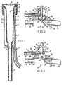
- Fig. 1 shows, in axial cross-section, one teat cup 1 of a cluster of four similar composite teat cups.
- the teat cup 1 has a rigid shell 2, with a pulse tube connector 3 at its lower end.
- a pulse tube 4 is shown in part, connected at the connector 3.
- a teat cup liner 5 of elastomeric material fits inside the teat cup shell 2 and forms airtight seals therewith, at the top by a downwardly-extending skirt part 6 and at the bottom by an integrally moulded grommet 7 which fits tightly in an outlet hole 8 at the bottom of the shell 2.
- the body 12 of the liner 5 extends within the shell 2, spaced from the inside wall of the shell 2 to leave an annular space 13 between the shell 2 and the liner 5.
- the liner 5 has a mouthpiece diaphragm 10 with a central circular aperture 11 dimensioned to fit closely around a teat of a cow to be milked.
- the liner extends as an integrally moulded short milk tube 9.
- the teat cup 1 of the invention is of conventional construction and is used in conventional manner, being fitted on a cows teat by the mouthpiece 11, a steady vacuum being applied to the interior of the liner body 12 by way of the short milk tube 9 and a pulsating vacuum being applied in the space 13, by way of the pulse tube 4.
- the wall of the liner 5 is made thicker in a region 14, beneath the skirt 6 and to one side, as shown at the top right in Fig. 1.
- a passage 15 extends from the liner outer wall nearly to the inner wall at a slit orifice 16.
- the residual wall material is pierced to form a short slit which, by reason of the elasticity of the liner material, is normally closed.
- the outer end of the passage 15 is dimensioned to receive and to hold an air admission tube 17.
- the air admission tube 17 passes downwardly in the space 13, out through the connector 3 and away from the teat cup 1 inside the pulse tube 4.
- a clawpiece shown generally at 20 comprising a pulsation block part 21 and a milk flow part 22.
- the pulsation block 21 is of conventional form and, whether of the simultaneous or alternate pulsation type, need not be described in detail in relation to the present invention.
- the milk flow part 22 of the clawpiece in respects unrelated to the present invention and not described herein, is of known form for a clawpiece for hydraulic milking and may correspond to the multi-valve clawpiece described in U.K. Patent No. 2,057,845.
- the milk flow part 22 has a milk chamber 23, into which milk passes through a milk connector, one of four such connectors, to which the end of the short milk tube 9 of Fig. 1 is connected.
- the arrangement is shown diagrammatically by a milk connector 24 and the end of the short milk tube 9 fitted thereto.
- Milk passes out of the milk chamber 23 by way of a connector 25, which connector is connected by way of a long milk tube, not shown, to a milk tank and source of steady vacuum, in normal manner.
- the connector 25 extends into the body of the milk flow part 22, the inner end providing an aperture 26 which lies in a plane which is oblique to the axis of the inner portion of connector 25.
- a movable, plate-shaped valve 27 is provided to shut off the steady vacuum and the milk flow out of the clawpiece 20, in the position shown in Fig. 3, or permit the flow of milk and maintenance of steady vacuum within the clawpiece 20, in the position shown in Fig. 2.
- the pulsation biock 2 has a composite connector 28, 29, one of four such connectors, to which the ends both of the pulse tube 4 and the air admission tube 17 of Fig. 1 are connected.
- the part 28 provides connection of the pulse tube 4 to a source of pulsating vacuum in conventional manner.
- the part 29 provides connection of the air admission tube 17 to an air channel 30, which may be opened to atmosphere or closed by an air-inlet valve linked to the steady vacuum and milk flow control valve.
- a control knob 31 positioned on top of the pulsation block 21 has a shaft 32 which extends through a bearing block 33, formed integrally with the pulsation block 21, and carries the plate-shaped valve 27 at its lower end. Near its lower end, the shaft 32 carries a flexible diaphragm 34, the circumferential edge of which is held in the body of the clawpiece 20, as is shown in the figures.
- the diaphragm seals the top of the milk chamber 23 from the pulsation block part 21 and also seals the air channel 30 from the milk chamber 23 due to the leakage path between the shaft 32 and bearing block 33.
- the control knob 31 is partly hollowed from its bottom to provide an outer skirt 35 and a circular top face 36, referenced in Fig. 3.
- an "0" ring 37 Into the top face 36, around the shaft 32, is fitted an "0" ring 37 in a position such that it abuts the top end of the bearing block 33, see Fig. 2.
- an "O" ring 38 Into the top face of the pulsation block 21, aligned with the outer skirt 35 of the control knob 31, is fitted an "O" ring 38, in a position such that the bottom face of the skirt 35 will abut it, see Fig. 2.
- the control knob 31 is depressed into the position shown in Fig. 2.
- the steady vacuum pressure is transmitted into the milk chamber 23 and the valve 27 is opened to permit milk flow through the connector 25.
- the pressure above the diaphragm 34 will be substantially at atmospheric pressure, having equalled atmospheric pressure in the air channel 30 by leakage between the shaft 32 and bearing block 33. Vacuum pressure acting upon the underside of the diaphragm 34 will cause the control knob 31 to be held in the milk-flow position of Fig. 2.
- the air-inlet valve constituted by the "O" rings 37 and 38 and the respective abutment surfaces will be closed, so that the air channel 30 is closed to the atmosphere and air is not admitted to the air admission tube 17 nor into the interior of the teat liner body 12.
- Steady vacuum is transmitted by way of the short milk tube 9 to the teat liner body 12
- pulsating vacuum is transmitted from the pulsation block 21, by way of the pulse tube 4, to the space 13 of the teat cup 1, so that the milking operation proceeds in the normal manner of hydraulic milking.
- the control knob 31 Upon completion of milk flow from the cow being milked, the control knob 31 is lifted, either manually or by known automatic means as the case may be, so that the control knob 31 assumes the position shown in Fig. 3. Now, the plate-shaped valve 27 abuts the inner end of the connector 25, thereby closing the milk flow exit from the milk chamber 23 and stopping the admission of steady vacuum pressure thereto. In the raised position of the control knob 31 shown in Fig. 3, the respective abutment surfaces are removed from both "O" rings 37 and 38, the air-inlet valve formed thereby is open to admit air from the atmosphere to the air channel 30. Air flows therefrom, by way of the air admission tube 17 to the passage 15.
- Closure of the vacuum and milk flow valve 27, 26 thus proceeds progressively. This enables residual milk, still in the bottom of the teat cup liner body 12 and in the short milk tube 9, to flow through the milk chamber 23 and out through the connector 25, while the valve 27, 26 is still partially open.
- the air inlet valve to the air channel 30 is, of course, opened immediately the respective abutment surfaces are removed from the "0" rings 37 and 38, so that full flow of air is permitted through the air admission tube 17. This flow progressively equalizes the air pressure within the teat cup liner 5 with the atmospheric pressure outside.
- Fig. 4 shows a teat cup 1 having a rigid shell 2, connector 3, pulse tube 4 and teat cup liner 5, as shown in the teat cup of Fig. 1.
- the liner 5 similarly has a passage 15 extending through the liner wall region 14.
- the orifice 16 is a permanently-open orifice.
- the air admission tube 17 is similarly connected to the passage 15 as in the example of Fig. 1 and similarly passes out of the teat cup by way of the space 13 and pulse tube 4.
- teat cup liner of Fig. 1 with the normally-closed orifice 16, is the preferred embodiment of teat cup liner, it is presently thought to be unimportant whether milk should enter the passage 15, since it is ejected by the admission of air through the air admission tube 17.
- the permanently-open orifice 16 of Fig. 4 is thus an acceptable alternative.
- a further alternative teat cup envisaged, not illustrated in the accompanying drawings, is one in which the rigid shell with pulse tube, teat cup liner with short milk tube and air admission tube are of unitary construction, forming a single replaceable unit.
- a clawpiece for hydraulic milking shown generally at 20.
- This comprises an upper part 21, which includes a conventional pulsation block, and a lower part, represented by the numeral 22, to which the upper part 21 is secured by a locking ring 40.
- the lower part 22 of the clawpiece 20 is shown in detail, in exploded perspective view of Fig. 10.
- the lower part 22 of the clawpiece comprises a base moulding 42 having an interior milk chamber 23.
- Four milk connectors 24, three of which are seen in the view of Fig. 10, are spaced around the moulding circumference and dimensioned to receive the ends of the four short milk tubes 9 of a cluster of teat cups.
- the entry of the connectors 24 into the chamber 23 form valve seatings 43, one of which is seen in the view of Fig. 10.
- Each valve seating 43 receives a steel ball 44, two of which are shown. These are normally retained by ball guides 45.
- a base cover 46 holds a small sealing ring 47 and a large sealing ring 48 and is secured to the underside of the moulding 42 by a retaining screw 49.
- a clawpiece hanging bracket 50 attaches to the moulding 42 at the side thereof.
- the moulding 42 indexes with the underside of a top moulding 51, which includes the connector 25 and which is shown as a member of the clawpiece upper part 21 in Fig. 5 and Fig. 6.
- the indexing is provided by moulded pins 52 which, together with the cut-away 53, shaped to receive the neck of the connector 25, ensure that lugs, which extend inwardly from the lower edge of the locking ring 40, engage four locking indentations 54 spaced around the side of the moulding 42 below its top edge.
- the moulding 42 is thereby locked to the underside of the top moulding 51 with an intermediate seal 55, shown as a ring seal in the drawing but which, when fitted in place, occupies a top edge slot 56, which follows the cut-away 53.
- the clawpiece top moulding 51 which includes the connector 25 and which retains the locking ring 40. Threaded internally, the moulding 51 holds a diaphragm retaining ring 57 which retains the peripheral edge of the diaphragm 34 mounted on the control shaft 32.
- a skirt moulding 58 is fitted above the moulding 51 with an intermediate skirt sealing ring 59.
- the pulsation block is positioned above the skirt moulding 58 with an intermediate skirt sealing ring 60.
- the pulsation block 21 is of conventional form, of either simultaneous or alternate pulsation type, and is provided with four composite connectors 28, 29, two of which are seen in the views of Fig. 5 and Fig. 6.
- the part 28 provides connection of a pulse tube 4 to a source of pulsating vacuum in conventional manner.
- the part 29 provides connection of an air admission tube 17 to the air channel 30.
- the control knob 31 is attached to the control shaft 32 near its top end and is held by a steel dome cap 61.
- the dome cap 61 and shaft 32 both have a transverse hole 62 to receive a pull ring 63.
- the interior underside of the control knob 31 has an annular seal pad 64 dimensioned to close the air channel 30 at the top, when the control knob 31 is in the position shown in Fig. 5. In this position of the control knob 31 also, an outer skirt portion 65 of the knob 31 abuts and seals against an air admission sealing ring 66 retained in a groove on the top face of a pulsation block screw top 67.
- the interior underside of the pulsation block screw top 67 has a circular steel knife edge 68 moulded integrally therewith with the edge pointing downwardly.
- the knife edge cuts into the top surface of all the air admission tubes 17, as is shown at the right hand side of Fig. 5 and Fig. 6, thereby to retain the ends of the air admission tubes 17 very securely in their connectors 29.
- the control elements of the clawpiece 20 upper part 21 have two steady control positions, as represented by the two figures Fig. 5 and Fig. 6.
- Fig. 5 shows the position for milking
- Fig. 6 shows the position set after milking.
- FIG. 7 The detail view of Fig. 7, corresponding to the control positions of Fig. 5, shows a part of the connector 25, itself part of the moulding 51, at its inner end where it extends into the milk chamber 23, providing an oblique aperture 26.
- control knob 31 is in its downward position, the seal pad 64 closes the top of the air channel 30 and the knob skirt 65 seals against the sealing ring 66.
- FIG. 8 The detail view of Fig. 8, corresponding to the control positions of Fig. 6, shows the connector 25 aperture 26 closed by the valve 27.
- control knob 31 is in its upper position, the seal pad 64 is lifted free of the top of the air channel 30 and the control knob skirt 65 is lifted free of the sealing ring 66, thereby admitting air to the air channel 30, to the connector parts 29 and thence to the air admission tubes 17 and the interior of the teat cup liners 5.
- the control transition from the Fig. 5 position to the Fig. 6 position is achieved in two stages.
- the first, and intermediate, stage is achieved by the initial lifting of control knob 31, whereby the lifting of seal pad 64 and the breaking of the seal with sealing ring 66 is achieved with only a partial closure of the valve 27 on the aperture 26.
- This first stage admits air to the air channel 30, air admission tubes 17 and to the teat cup liner mouthpieces. This eases removal of the teat cup cluster while still permitting milk flow from the teat cup liner bodies, from the short milk tubes 9 and from the milk chamber 23. Completion of the movement of the control knob 31 completes the control action by closing the valve 27.
- the two-stage operation of the control members of the clawpiece is facilitated by a control shaft position indexing arrangement shown in Fig. 9.
- the shaft 32 has a flat portion 70 with sloping sides 71 milled in one face.
- An indexing steel ball 72 is housed in a bore 75 within the body of the pulsation block and the ball 72 is spring loaded by a helical spring 73 and tension screw 74 also housed in the pulsation block bore 75.
- the milled flat 70 is positioned, in relation to the longitudinal movement of the shaft 32, so that the first stage of movement is easily made and a noticeable further effort is required for the subsequent movement.
- the method of hydraulic milking employing apparatus as described herein requires the fitting of teat cups to a cow in conventional manner.
- the control knob 31 is set as is shown in Fig. 2 or Fig. 5, whereby steady vacuum is admitted to the milk chamber 23 and air is excluded from the air admission tubes 17 and from the associated teat cup liners. Pulsating vacuum is supplied to the pulse tubes 4 from the pulsation block of the clawpiece and milking proceeds in the normal manner for hydraulic milking.
- the clawpiece control knob 31 is moved, first to release air into the air-admission tubes 17, to release the vacuum and to facilitate removal of the teat cups, and secondly to close the milk outlet from the milk chamber 23 of the clawpiece and to shut off the steady vacuum supplied through the long milk tube.
Landscapes
- Life Sciences & Earth Sciences (AREA)
- Animal Husbandry (AREA)
- Environmental Sciences (AREA)
- External Artificial Organs (AREA)
Description
- This invention relates to automatic milking apparatus.
- Automatic milking apparatus includes, for each cow milking unit, a clawpiece and a cluster of four teat cups connected to the clawpiece. Each teat cup has a rigid shell and an internal flexible liner. This liner has a topmost mouthpiece diaphragm with a circular mouthpiece and a body part inside the shell body. The liner extends through the bottom of the shell body as a short milk tube. This tube is connected to the clawpiece and thence, by way of a long milk tube, to a source of steady vacuum.
- An annular space, between the teat cup shell and the test cup liner, is connected to the clawpiece by a pulse tube and thence to a source of pulsating vacuum.
- For milking, the four teat cups are placed around the cow's teats, the liner mouthpiece of each teat cup being fitted over the respective teat. The teat cups are held in position during the milking operation by adhesion, due to the steady vacuum applied for the milking operation. The pulsating vacuum applied between the teat cup liner and shell causes the liner body to dilate and contract again, thus promoting the flow of milk by simulating suckling. After completion of the milking operation, the teat cup cluster is removed from the cow's teats, either manually or by automatic means.
- In milking methods which are conventional at the present date, in which a continuous air bleed is provided at the clawpiece or upstream of the clawpiece, the steady vacuum induced adhesion is automatically broken when the vacuum supply is shut off at the end of milking, so that the teat cup cluster is easily removed from the milked cow.
- However, a more modern milking method, known as the hydraulic milking method, has recently been introduced. This utilises hydraulic milking apparatus in which milk from the teats is drawn past one or more non-return valves and there is no air bleed into the milk flow upstream of the valve or valves during milking, that is to say during the process of drawing milk from an individual cow. In consequence, the steady vacuum induced adhesion of the teat cup liner to the cow's teat is not broken when the vacuum supply is shut off after milking. Some other means is thus needed to break the vacuum adhesion before the teat cups can easily be removed from the milking cow.
- Hydraulic milking apparatus as hereinbefore defined was first disclosed in GB-A-2159685, but that specification does not identify the problem and consequently does not propose a solution for it.
- The object of the present invention is to provide automatic hydraulic milking apparatus, particularly the teat cup and clawpiece components thereof, in which air may be admitted positively into the body space of the teat cup liner, at will upon the completion of the milking operation.
- Accordingly, the present invention provides automatic hydraulic milking apparatus comprising at least one cluster of teat cups, each teat cup having a teat cup liner with a body part fitting within a teat cup shell, the shell having a vacuum pulse tube connected to pressure the shell interior space between the shell and the liner body, the liner body having an air passage extending therethrough and an air admission tube connected to the air passage, the air admission tube extending within the shell interior space and through the vacuum pulse tube to air admission control means, whereby air may be admitted to the liner body interior at will upon the completion of a milking operation.
- Preferably, the apparatus further comprises a clawpiece having a pulsation block part and a milk flow part, each teat cup having a pulse tube thereof connected to a connector of the pulsation block part and having the said air admission tube within the pulse tube connected to an air-flow connector provided by said clawpiece, said clawpiece further having a movable control member connected to a steady vacuum control and milk control valve within the milk flow part of said clawpiece, and an air-inlet valve, controlling air-flow from atmosphere to the said air-flow connector, linked to the said control member, said air-inlet valve being closed when the said steady vacuum control and milk flow control valve is open and being open when the said steady vacuum control and milk flow control valve is closed.
- Two embodiments of the invention will be described, by way of example, with reference to the accompanying drawings, wherein the same or similar parts are indicated by the same reference numerals throughout the several drawings, and in which:-
- Fig. 1 is an axial cross-section view of one teat cup of a cluster of four, showing the rigid shell, elastomeric teat cup liner, with part of a short milk tube extending therefrom, part of a pulse tube connected to the teat cup shell and an air admission tube connected to a passage through the liner and extending away from the teat cup shell inside the pulse tube;
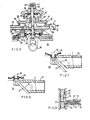
- Fig. 2 is a part elevation, part axial cross-section view of a clawpiece for hydraulic milking, showing a steady vacuum and milk-flow valve open and an air-inlet valve closed, as during a milking operation;
- Fig. 3 is a corresponding view to Fig. 2, showing the steady vacuum and milk-flow valve closed and the air-inlet valve open, as at completion of a milking operation.
- Fig. 4 is an axial cross-section view of an alternative teat cup to that shown in Fig. 1;
- Figs. 5 and 6 are part elevation, part axial cross-section views of the upper part of an alternative clawpiece to that shown in Figs. 2 and 3;
- Fig. 5 is the view showing the steady vacuum and milk-flow valve open and the air-inlet valve closed, as during a milking operation;
- Fig. 6 is the view showing the steady vacuum and milk-flow valve closed and the air-inlet valve open, as at the completion of a milking operation;
- Fig. 7 is a detail view of the clawpiece parts of Fig. 5, part elevation and part cross-section in a plane perpendicular to that of Fig. 5, showing the steady vacuum and milk flow valve open;
- Fig. 8 is a corresponding detail view of the clawpiece parts of Fig. 6, showing the steady vacuum and milk flow valve closed;
- Fig. 9 is a detail view, part in elevation and part in axial cross-section, showing a two-stage indexing of the clawpiece valve control shaft; and
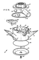
- Fig. 10 is an exploded, perspective view of the lower part of the clawpiece of which the upper part is shown in Fig. 5 and Fig. 6, with one member of the upper part also shown in perspective.
- Fig. 1 shows, in axial cross-section, one teat cup 1 of a cluster of four similar composite teat cups. The teat cup 1 has a
rigid shell 2, with a pulse tube connector 3 at its lower end. A pulse tube 4 is shown in part, connected at the connector 3. Ateat cup liner 5 of elastomeric material fits inside theteat cup shell 2 and forms airtight seals therewith, at the top by a downwardly-extendingskirt part 6 and at the bottom by an integrally moulded grommet 7 which fits tightly in anoutlet hole 8 at the bottom of theshell 2. Thebody 12 of theliner 5 extends within theshell 2, spaced from the inside wall of theshell 2 to leave anannular space 13 between theshell 2 and theliner 5. At its top, theliner 5 has amouthpiece diaphragm 10 with a centralcircular aperture 11 dimensioned to fit closely around a teat of a cow to be milked. At the bottom, below the grommet 7, the liner extends as an integrally moulded short milk tube 9. - In the parts as so far described, the teat cup 1 of the invention is of conventional construction and is used in conventional manner, being fitted on a cows teat by the
mouthpiece 11, a steady vacuum being applied to the interior of theliner body 12 by way of the short milk tube 9 and a pulsating vacuum being applied in thespace 13, by way of the pulse tube 4. - However, since the apparatus of the invention is intended for hydraulic milking, no provision is made for an air bleed at or upstream of the clawpiece, to be described, during the milking operation itself. Provision is made to admit air into the interior of the
liner body 12, just below themouthpiece diaphragm 10, at will upon completion of the milking operation. - The wall of the
liner 5 is made thicker in aregion 14, beneath theskirt 6 and to one side, as shown at the top right in Fig. 1. Here, apassage 15 extends from the liner outer wall nearly to the inner wall at aslit orifice 16. To form theorifice 16, the residual wall material is pierced to form a short slit which, by reason of the elasticity of the liner material, is normally closed. The outer end of thepassage 15 is dimensioned to receive and to hold anair admission tube 17. Theair admission tube 17 passes downwardly in thespace 13, out through the connector 3 and away from the teat cup 1 inside the pulse tube 4. - Referring now to Fig. 2, there is shown in part, generally in axial cross-section and part in elevation, a clawpiece shown generally at 20, comprising a
pulsation block part 21 and amilk flow part 22. - The
pulsation block 21 is of conventional form and, whether of the simultaneous or alternate pulsation type, need not be described in detail in relation to the present invention. The milk flowpart 22 of the clawpiece, in respects unrelated to the present invention and not described herein, is of known form for a clawpiece for hydraulic milking and may correspond to the multi-valve clawpiece described in U.K. Patent No. 2,057,845. - The
milk flow part 22 has amilk chamber 23, into which milk passes through a milk connector, one of four such connectors, to which the end of the short milk tube 9 of Fig. 1 is connected. The arrangement is shown diagrammatically by amilk connector 24 and the end of the short milk tube 9 fitted thereto. Milk passes out of themilk chamber 23 by way of aconnector 25, which connector is connected by way of a long milk tube, not shown, to a milk tank and source of steady vacuum, in normal manner. Theconnector 25 extends into the body of themilk flow part 22, the inner end providing anaperture 26 which lies in a plane which is oblique to the axis of the inner portion ofconnector 25. A movable, plate-shaped valve 27 is provided to shut off the steady vacuum and the milk flow out of theclawpiece 20, in the position shown in Fig. 3, or permit the flow of milk and maintenance of steady vacuum within theclawpiece 20, in the position shown in Fig. 2. - The
pulsation biock 2 has acomposite connector air admission tube 17 of Fig. 1 are connected. Thepart 28 provides connection of the pulse tube 4 to a source of pulsating vacuum in conventional manner. Thepart 29 provides connection of theair admission tube 17 to anair channel 30, which may be opened to atmosphere or closed by an air-inlet valve linked to the steady vacuum and milk flow control valve. - The construction of these two valves is shown in both Figs. 2 and 3. A
control knob 31 positioned on top of thepulsation block 21 has ashaft 32 which extends through abearing block 33, formed integrally with thepulsation block 21, and carries the plate-shaped valve 27 at its lower end. Near its lower end, theshaft 32 carries aflexible diaphragm 34, the circumferential edge of which is held in the body of theclawpiece 20, as is shown in the figures. The diaphragm seals the top of themilk chamber 23 from thepulsation block part 21 and also seals theair channel 30 from themilk chamber 23 due to the leakage path between theshaft 32 and bearingblock 33. Thecontrol knob 31 is partly hollowed from its bottom to provide anouter skirt 35 and a circulartop face 36, referenced in Fig. 3. Into thetop face 36, around theshaft 32, is fitted an "0"ring 37 in a position such that it abuts the top end of thebearing block 33, see Fig. 2. Into the top face of thepulsation block 21, aligned with theouter skirt 35 of thecontrol knob 31, is fitted an "O"ring 38, in a position such that the bottom face of theskirt 35 will abut it, see Fig. 2. - For. milking operation, the
control knob 31 is depressed into the position shown in Fig. 2. The steady vacuum pressure is transmitted into themilk chamber 23 and thevalve 27 is opened to permit milk flow through theconnector 25. At this time, the pressure above thediaphragm 34 will be substantially at atmospheric pressure, having equalled atmospheric pressure in theair channel 30 by leakage between theshaft 32 and bearingblock 33. Vacuum pressure acting upon the underside of thediaphragm 34 will cause thecontrol knob 31 to be held in the milk-flow position of Fig. 2. At the same time, the air-inlet valve constituted by the "O" rings 37 and 38 and the respective abutment surfaces will be closed, so that theair channel 30 is closed to the atmosphere and air is not admitted to theair admission tube 17 nor into the interior of theteat liner body 12. Steady vacuum is transmitted by way of the short milk tube 9 to theteat liner body 12, pulsating vacuum is transmitted from thepulsation block 21, by way of the pulse tube 4, to thespace 13 of the teat cup 1, so that the milking operation proceeds in the normal manner of hydraulic milking. - Upon completion of milk flow from the cow being milked, the
control knob 31 is lifted, either manually or by known automatic means as the case may be, so that thecontrol knob 31 assumes the position shown in Fig. 3. Now, the plate-shapedvalve 27 abuts the inner end of theconnector 25, thereby closing the milk flow exit from themilk chamber 23 and stopping the admission of steady vacuum pressure thereto. In the raised position of thecontrol knob 31 shown in Fig. 3, the respective abutment surfaces are removed from both "O" rings 37 and 38, the air-inlet valve formed thereby is open to admit air from the atmosphere to theair channel 30. Air flows therefrom, by way of theair admission tube 17 to thepassage 15. Since near vacuum pressure still persists in the interior of theteat cup liner 5, which at this time still retains the cow's teat which has been milked, air will pass from thepassage 15, through theslit orifice 16 into the interior of theteat cup liner 5, beneath themouthpiece diaphragm 10 and around the cow's teat. Accordingly, the pressure within theteat cup liner 5 will rapidly rise to the atmospheric pressure outside the teat cup 1 and the easy removal of the teat cup 1, and correspondingly the other three teat cups of the cluster, is facilitated. In practice, thecontrol knob 31 is raised slowly, from its Fig. 2 position to its Fig. 3 position, as will tend to be the case naturally, due to the initial vacuum pressure below thediaphragm 34. Closure of the vacuum andmilk flow valve cup liner body 12 and in the short milk tube 9, to flow through themilk chamber 23 and out through theconnector 25, while thevalve air channel 30 is, of course, opened immediately the respective abutment surfaces are removed from the "0" rings 37 and 38, so that full flow of air is permitted through theair admission tube 17. This flow progressively equalizes the air pressure within theteat cup liner 5 with the atmospheric pressure outside. - Fig. 4 shows a teat cup 1 having a
rigid shell 2, connector 3, pulse tube 4 andteat cup liner 5, as shown in the teat cup of Fig. 1. Theliner 5 similarly has apassage 15 extending through theliner wall region 14. In this example, theorifice 16 is a permanently-open orifice. Theair admission tube 17 is similarly connected to thepassage 15 as in the example of Fig. 1 and similarly passes out of the teat cup by way of thespace 13 and pulse tube 4. - Although the teat cup liner of Fig. 1, with the normally-closed
orifice 16, is the preferred embodiment of teat cup liner, it is presently thought to be unimportant whether milk should enter thepassage 15, since it is ejected by the admission of air through theair admission tube 17. The permanently-open orifice 16 of Fig. 4 is thus an acceptable alternative. - A further alternative teat cup envisaged, not illustrated in the accompanying drawings, is one in which the rigid shell with pulse tube, teat cup liner with short milk tube and air admission tube are of unitary construction, forming a single replaceable unit.
- Comparing now the clawpiece of Fig. 5 and Fig. 6 with the clawpiece of Fig. 2 and Fig. 3, there is shown in Fig. 5 and Fig. 6 a clawpiece for hydraulic milking shown generally at 20. This comprises an
upper part 21, which includes a conventional pulsation block, and a lower part, represented by the numeral 22, to which theupper part 21 is secured by a lockingring 40. Thelower part 22 of theclawpiece 20 is shown in detail, in exploded perspective view of Fig. 10. - In Fig. 10, the
lower part 22 of the clawpiece comprises abase moulding 42 having aninterior milk chamber 23. Fourmilk connectors 24, three of which are seen in the view of Fig. 10, are spaced around the moulding circumference and dimensioned to receive the ends of the four short milk tubes 9 of a cluster of teat cups. The entry of theconnectors 24 into thechamber 23 form valve seatings 43, one of which is seen in the view of Fig. 10. Each valve seating 43 receives asteel ball 44, two of which are shown. These are normally retained by ball guides 45. Abase cover 46 holds asmall sealing ring 47 and alarge sealing ring 48 and is secured to the underside of themoulding 42 by a retainingscrew 49. Aclawpiece hanging bracket 50 attaches to themoulding 42 at the side thereof. Themoulding 42 indexes with the underside of atop moulding 51, which includes theconnector 25 and which is shown as a member of the clawpieceupper part 21 in Fig. 5 and Fig. 6. The indexing is provided by mouldedpins 52 which, together with the cut-away 53, shaped to receive the neck of theconnector 25, ensure that lugs, which extend inwardly from the lower edge of the lockingring 40, engage four lockingindentations 54 spaced around the side of themoulding 42 below its top edge. Themoulding 42 is thereby locked to the underside of thetop moulding 51 with anintermediate seal 55, shown as a ring seal in the drawing but which, when fitted in place, occupies atop edge slot 56, which follows the cut-away 53. - Returning to Fig. 5 and Fig. 6, there is shown the clawpiece
top moulding 51, which includes theconnector 25 and which retains the lockingring 40. Threaded internally, themoulding 51 holds adiaphragm retaining ring 57 which retains the peripheral edge of thediaphragm 34 mounted on thecontrol shaft 32. - A
skirt moulding 58 is fitted above themoulding 51 with an intermediateskirt sealing ring 59. The pulsation block is positioned above theskirt moulding 58 with an intermediateskirt sealing ring 60. - The
pulsation block 21 is of conventional form, of either simultaneous or alternate pulsation type, and is provided with fourcomposite connectors part 28 provides connection of a pulse tube 4 to a source of pulsating vacuum in conventional manner. Thepart 29 provides connection of anair admission tube 17 to theair channel 30. - The
control knob 31 is attached to thecontrol shaft 32 near its top end and is held by asteel dome cap 61. Thedome cap 61 andshaft 32 both have atransverse hole 62 to receive apull ring 63. - The interior underside of the
control knob 31 has anannular seal pad 64 dimensioned to close theair channel 30 at the top, when thecontrol knob 31 is in the position shown in Fig. 5. In this position of thecontrol knob 31 also, anouter skirt portion 65 of theknob 31 abuts and seals against an airadmission sealing ring 66 retained in a groove on the top face of a pulsationblock screw top 67. - The interior underside of the pulsation
block screw top 67 has a circularsteel knife edge 68 moulded integrally therewith with the edge pointing downwardly. In assembly, as the screw top is tightened onto the pulsation block, the knife edge cuts into the top surface of all theair admission tubes 17, as is shown at the right hand side of Fig. 5 and Fig. 6, thereby to retain the ends of theair admission tubes 17 very securely in theirconnectors 29. - The control elements of the
clawpiece 20upper part 21 have two steady control positions, as represented by the two figures Fig. 5 and Fig. 6. Fig. 5 shows the position for milking, Fig. 6 shows the position set after milking. - The detail view of Fig. 7, corresponding to the control positions of Fig. 5, shows a part of the
connector 25, itself part of themoulding 51, at its inner end where it extends into themilk chamber 23, providing anoblique aperture 26. The lower end of thecontrol shaft 32, below thediaphragm 34, carries the plate-shapedvalve 27, which in the position of Fig. 7 is open to permit the maintenance of steady vacuum in themilk chamber 23, from the long milk tube, not shown, connected to theconnector 25, and also the free passage of milk from themilk chamber 23 into the long milk tube. - At this time, the
control knob 31 is in its downward position, theseal pad 64 closes the top of theair channel 30 and theknob skirt 65 seals against the sealingring 66. - The detail view of Fig. 8, corresponding to the control positions of Fig. 6, shows the
connector 25aperture 26 closed by thevalve 27. - At this time, the
control knob 31 is in its upper position, theseal pad 64 is lifted free of the top of theair channel 30 and thecontrol knob skirt 65 is lifted free of the sealingring 66, thereby admitting air to theair channel 30, to theconnector parts 29 and thence to theair admission tubes 17 and the interior of theteat cup liners 5. - With the clawpiece construction shown in Fig. 5 and Fig. 6, the control transition from the Fig. 5 position to the Fig. 6 position is achieved in two stages. The first, and intermediate, stage is achieved by the initial lifting of
control knob 31, whereby the lifting ofseal pad 64 and the breaking of the seal with sealingring 66 is achieved with only a partial closure of thevalve 27 on theaperture 26. This first stage admits air to theair channel 30,air admission tubes 17 and to the teat cup liner mouthpieces. This eases removal of the teat cup cluster while still permitting milk flow from the teat cup liner bodies, from the short milk tubes 9 and from themilk chamber 23. Completion of the movement of thecontrol knob 31 completes the control action by closing thevalve 27. - The two-stage operation of the control members of the clawpiece is facilitated by a control shaft position indexing arrangement shown in Fig. 9. The
shaft 32 has aflat portion 70 with slopingsides 71 milled in one face. Anindexing steel ball 72 is housed in abore 75 within the body of the pulsation block and theball 72 is spring loaded by ahelical spring 73 andtension screw 74 also housed in the pulsation block bore 75. The milled flat 70 is positioned, in relation to the longitudinal movement of theshaft 32, so that the first stage of movement is easily made and a noticeable further effort is required for the subsequent movement. - The method of hydraulic milking employing apparatus as described herein requires the fitting of teat cups to a cow in conventional manner. The
control knob 31 is set as is shown in Fig. 2 or Fig. 5, whereby steady vacuum is admitted to themilk chamber 23 and air is excluded from theair admission tubes 17 and from the associated teat cup liners. Pulsating vacuum is supplied to the pulse tubes 4 from the pulsation block of the clawpiece and milking proceeds in the normal manner for hydraulic milking. In this manner of milking, as has been explained, no air admission is permitted at or up-stream of the clawpiece and theball valves 44 operate to seal themilk intake connectors 24, preventing any reverse flow of milk.Atthe completion of the milking of a cow,theclawpiece control knob 31 is moved, first to release air into the air-admission tubes 17, to release the vacuum and to facilitate removal of the teat cups, and secondly to close the milk outlet from themilk chamber 23 of the clawpiece and to shut off the steady vacuum supplied through the long milk tube.
Claims (6)
Applications Claiming Priority (2)
| Application Number | Priority Date | Filing Date | Title |
|---|---|---|---|
| GB868611471A GB8611471D0 (en) | 1986-05-10 | 1986-05-10 | Automatic milking apparatus |
| GB8611471 | 1986-05-10 |
Publications (3)
| Publication Number | Publication Date |
|---|---|
| EP0246759A2 EP0246759A2 (en) | 1987-11-25 |
| EP0246759A3 EP0246759A3 (en) | 1988-10-12 |
| EP0246759B1 true EP0246759B1 (en) | 1991-01-23 |
Family
ID=10597688
Family Applications (1)
| Application Number | Title | Priority Date | Filing Date |
|---|---|---|---|
| EP87303564A Expired EP0246759B1 (en) | 1986-05-10 | 1987-04-23 | Improvements in or relating to automatic milking apparatus |
Country Status (5)
| Country | Link |
|---|---|
| US (1) | US4840141A (en) |
| EP (1) | EP0246759B1 (en) |
| DE (1) | DE3767561D1 (en) |
| GB (2) | GB8611471D0 (en) |
| NZ (1) | NZ220174A (en) |
Families Citing this family (11)
| Publication number | Priority date | Publication date | Assignee | Title |
|---|---|---|---|---|
| DE3818116A1 (en) * | 1988-05-27 | 1989-11-30 | Fritz Happel | MILKING SYSTEM |
| GB8926950D0 (en) * | 1989-11-29 | 1990-01-17 | Ambic Equip Ltd | Automatic milking apparatus |
| US5161482A (en) * | 1990-06-01 | 1992-11-10 | British Technology Group Limited | Automatic milking apparatus |
| US5493995A (en) | 1994-05-16 | 1996-02-27 | Alfa Laval Agri, Inc. | Collapsing teat cup liner with tapering barrel wall |
| ES2217746T3 (en) * | 1998-03-23 | 2004-11-01 | Silclear Limited | PEZONERA COVER. |
| AU141009S (en) | 1999-06-10 | 2000-06-27 | Delaval Holding Ab | A teatcup liner |
| IES20020390A2 (en) * | 2002-05-15 | 2003-11-26 | Aratech Ltd | An end cap for a tubular shell of a milk liner assembley |
| DE102004004057B4 (en) * | 2004-01-27 | 2008-07-10 | Maier Jun., Jakob | liner |
| USD715008S1 (en) * | 2012-10-01 | 2014-10-07 | Delaval Holding Ab | Teat cup liner |
| WO2014144297A1 (en) * | 2013-03-15 | 2014-09-18 | Lauren Agrisystems, Ltd. | Milking liner and milk hose |
| WO2016099384A1 (en) * | 2014-12-19 | 2016-06-23 | Delaval Holding Ab | A teatcup |
Family Cites Families (12)
| Publication number | Priority date | Publication date | Assignee | Title |
|---|---|---|---|---|
| SE159259C1 (en) * | 1955-09-29 | 1957-06-18 | ||
| US3255732A (en) * | 1964-09-28 | 1966-06-14 | John W Raht | Method and apparatus for teat cup inflation control in machine milking |
| US3611993A (en) * | 1969-11-10 | 1971-10-12 | Laval Separator Co De | Valving arrangement for operating teat cup liners |
| DE2046276C3 (en) * | 1970-09-18 | 1975-07-03 | Jakob 8939 Tuerkheim Maier Jun. | Milking cups for milking machines |
| DE2312756A1 (en) * | 1973-03-14 | 1974-09-26 | Jun Jakob Maier | ELASTIC SUCTION INSERT FOR MILKING CUP OF MILKING MACHINES |
| SU665861A1 (en) * | 1976-12-09 | 1979-06-05 | Опытное Проектно-Конструкторскотехнологическое Бюро Сибирского Научно-Исследовательского И Проектнотехнологического Института Животноводства Сибирского Отделения Всесоюзной Академии Сельскохозяйственных Наук Им. В.И.Ленина | Milking cup |
| GB2057845B (en) * | 1979-09-11 | 1983-01-19 | Nat Res Dev | Multi-valve clawpiece |
| US4303038A (en) * | 1980-02-21 | 1981-12-01 | Babson Bros. Co. | Teat cup with air inlet |
| US4353704A (en) * | 1980-03-28 | 1982-10-12 | Rexnord Inc. | Piloted flexible coupling |
| SU961611A2 (en) * | 1981-06-05 | 1982-09-30 | Полтавский Ордена Трудового Красного Знамени Сельскохозяйственный Институт | Milking sleeve |
| SU1113053A2 (en) * | 1982-10-01 | 1984-09-15 | Vasilev Mikhail N | Single-chamber teat cup |
| DE3379933D1 (en) * | 1983-07-19 | 1989-07-06 | Hoefelmayr Bio Melktech | Air inlet valve for the milk line of a teat cup or a milk claw |
-
1986
- 1986-05-10 GB GB868611471A patent/GB8611471D0/en active Pending
-
1987
- 1987-04-23 EP EP87303564A patent/EP0246759B1/en not_active Expired
- 1987-04-23 DE DE8787303564T patent/DE3767561D1/en not_active Expired - Lifetime
- 1987-04-23 GB GB8709618A patent/GB2189976B/en not_active Expired - Lifetime
- 1987-04-30 NZ NZ220174A patent/NZ220174A/en unknown
- 1987-05-07 US US07/046,692 patent/US4840141A/en not_active Expired - Lifetime
Also Published As
| Publication number | Publication date |
|---|---|
| GB2189976A (en) | 1987-11-11 |
| GB8709618D0 (en) | 1987-05-28 |
| GB2189976B (en) | 1990-07-18 |
| US4840141A (en) | 1989-06-20 |
| NZ220174A (en) | 1989-10-27 |
| EP0246759A3 (en) | 1988-10-12 |
| GB8611471D0 (en) | 1986-06-18 |
| DE3767561D1 (en) | 1991-02-28 |
| EP0246759A2 (en) | 1987-11-25 |
Similar Documents
| Publication | Publication Date | Title |
|---|---|---|
| US4936254A (en) | Automatic milking apparatus | |
| US5134967A (en) | Teat cup for hydraulic milking apparatus | |
| US4840141A (en) | Automatic milking apparatus | |
| US4454893A (en) | Low-noise diaphragm for use in exhalation valve | |
| US3014455A (en) | Claw pieces for milking machines | |
| US7419069B2 (en) | Valve for a drinking receptacle | |
| US2986117A (en) | Milking machine teat cups | |
| EP1806050B1 (en) | Teatcup assembly | |
| NZ201994A (en) | Feeding bottle with air intake valve | |
| US4604969A (en) | Milking inflation including air vent | |
| US4280445A (en) | Methods of and/or apparatus for milking animals | |
| CA1200783A (en) | Valve for use in a suction line | |
| JPS6382991A (en) | Filler | |
| US4998554A (en) | Food pasteurization system vacuum breaker | |
| US3799185A (en) | Breathing valve | |
| SE500512C2 (en) | Teat cup for milking facilities | |
| US4671209A (en) | Teat cup claw | |
| NZ192198A (en) | Vacuum closed venting valve | |
| US5857424A (en) | Position-adaptor for milking machine inflations | |
| SE423300B (en) | CUTTING MACHINE CENTER FOR MILKING MACHINE | |
| US20020134385A1 (en) | Regulator for underwater breathing devices | |
| US3493139A (en) | Infant feeding device | |
| EP0717927A1 (en) | Teat cup assembly and liner therefor | |
| US1358987A (en) | Milking-machine | |
| US2630290A (en) | Packless valve stem assembly |
Legal Events
| Date | Code | Title | Description |
|---|---|---|---|
| PUAI | Public reference made under article 153(3) epc to a published international application that has entered the european phase |
Free format text: ORIGINAL CODE: 0009012 |
|
| AK | Designated contracting states |
Kind code of ref document: A2 Designated state(s): BE DE FR IT NL |
|
| 17P | Request for examination filed |
Effective date: 19880511 |
|
| PUAL | Search report despatched |
Free format text: ORIGINAL CODE: 0009013 |
|
| AK | Designated contracting states |
Kind code of ref document: A3 Designated state(s): BE DE FR IT NL |
|
| 17Q | First examination report despatched |
Effective date: 19890914 |
|
| GRAA | (expected) grant |
Free format text: ORIGINAL CODE: 0009210 |
|
| AK | Designated contracting states |
Kind code of ref document: B1 Designated state(s): BE DE FR IT NL |
|
| PG25 | Lapsed in a contracting state [announced via postgrant information from national office to epo] |
Ref country code: IT Free format text: LAPSE BECAUSE OF FAILURE TO SUBMIT A TRANSLATION OF THE DESCRIPTION OR TO PAY THE FEE WITHIN THE PRE;WARNING: LAPSES OF ITALIAN PATENTS WITH EFFECTIVE DATE BEFORE 2007 MAY HAVE OCCURRED AT ANY TIME BEFORE 2007. THE CORRECT EFFECTIVE DATE MAY BE DIFFERENT FROM THE ONE RECORDED.SCRIBED TIME-LIMIT Effective date: 19910123 Ref country code: BE Effective date: 19910123 |
|
| REF | Corresponds to: |
Ref document number: 3767561 Country of ref document: DE Date of ref document: 19910228 |
|
| ET | Fr: translation filed | ||
| PLBE | No opposition filed within time limit |
Free format text: ORIGINAL CODE: 0009261 |
|
| STAA | Information on the status of an ep patent application or granted ep patent |
Free format text: STATUS: NO OPPOSITION FILED WITHIN TIME LIMIT |
|
| 26N | No opposition filed | ||
| PGFP | Annual fee paid to national office [announced via postgrant information from national office to epo] |
Ref country code: NL Payment date: 20040406 Year of fee payment: 18 |
|
| PGFP | Annual fee paid to national office [announced via postgrant information from national office to epo] |
Ref country code: FR Payment date: 20040408 Year of fee payment: 18 |
|
| PGFP | Annual fee paid to national office [announced via postgrant information from national office to epo] |
Ref country code: DE Payment date: 20040506 Year of fee payment: 18 |
|
| PG25 | Lapsed in a contracting state [announced via postgrant information from national office to epo] |
Ref country code: DE Free format text: LAPSE BECAUSE OF NON-PAYMENT OF DUE FEES Effective date: 20051101 Ref country code: NL Free format text: LAPSE BECAUSE OF NON-PAYMENT OF DUE FEES Effective date: 20051101 |
|
| PG25 | Lapsed in a contracting state [announced via postgrant information from national office to epo] |
Ref country code: FR Free format text: LAPSE BECAUSE OF NON-PAYMENT OF DUE FEES Effective date: 20051230 |
|
| NLV4 | Nl: lapsed or anulled due to non-payment of the annual fee |
Effective date: 20051101 |
|
| REG | Reference to a national code |
Ref country code: FR Ref legal event code: ST Effective date: 20051230 |