EP0246085A2 - Surveillance systems - Google Patents
Surveillance systems Download PDFInfo
- Publication number
- EP0246085A2 EP0246085A2 EP87304251A EP87304251A EP0246085A2 EP 0246085 A2 EP0246085 A2 EP 0246085A2 EP 87304251 A EP87304251 A EP 87304251A EP 87304251 A EP87304251 A EP 87304251A EP 0246085 A2 EP0246085 A2 EP 0246085A2
- Authority
- EP
- European Patent Office
- Prior art keywords
- signal
- image processing
- video signal
- supplied
- image
- Prior art date
- Legal status (The legal status is an assumption and is not a legal conclusion. Google has not performed a legal analysis and makes no representation as to the accuracy of the status listed.)
- Granted
Links
Images


Classifications
-
- G—PHYSICS
- G08—SIGNALLING
- G08B—SIGNALLING SYSTEMS, e.g. PERSONAL CALLING SYSTEMS; ORDER TELEGRAPHS; ALARM SYSTEMS
- G08B13/00—Burglar, theft or intruder alarms
- G08B13/18—Actuation by interference with heat, light, or radiation of shorter wavelength; Actuation by intruding sources of heat, light, or radiation of shorter wavelength
- G08B13/189—Actuation by interference with heat, light, or radiation of shorter wavelength; Actuation by intruding sources of heat, light, or radiation of shorter wavelength using passive radiation detection systems
- G08B13/194—Actuation by interference with heat, light, or radiation of shorter wavelength; Actuation by intruding sources of heat, light, or radiation of shorter wavelength using passive radiation detection systems using image scanning and comparing systems
- G08B13/196—Actuation by interference with heat, light, or radiation of shorter wavelength; Actuation by intruding sources of heat, light, or radiation of shorter wavelength using passive radiation detection systems using image scanning and comparing systems using television cameras
- G08B13/19678—User interface
- G08B13/1968—Interfaces for setting up or customising the system
-
- G—PHYSICS
- G08—SIGNALLING
- G08B—SIGNALLING SYSTEMS, e.g. PERSONAL CALLING SYSTEMS; ORDER TELEGRAPHS; ALARM SYSTEMS
- G08B13/00—Burglar, theft or intruder alarms
- G08B13/18—Actuation by interference with heat, light, or radiation of shorter wavelength; Actuation by intruding sources of heat, light, or radiation of shorter wavelength
- G08B13/189—Actuation by interference with heat, light, or radiation of shorter wavelength; Actuation by intruding sources of heat, light, or radiation of shorter wavelength using passive radiation detection systems
- G08B13/194—Actuation by interference with heat, light, or radiation of shorter wavelength; Actuation by intruding sources of heat, light, or radiation of shorter wavelength using passive radiation detection systems using image scanning and comparing systems
- G08B13/196—Actuation by interference with heat, light, or radiation of shorter wavelength; Actuation by intruding sources of heat, light, or radiation of shorter wavelength using passive radiation detection systems using image scanning and comparing systems using television cameras
- G08B13/19602—Image analysis to detect motion of the intruder, e.g. by frame subtraction
- G08B13/1961—Movement detection not involving frame subtraction, e.g. motion detection on the basis of luminance changes in the image
-
- G—PHYSICS
- G08—SIGNALLING
- G08B—SIGNALLING SYSTEMS, e.g. PERSONAL CALLING SYSTEMS; ORDER TELEGRAPHS; ALARM SYSTEMS
- G08B13/00—Burglar, theft or intruder alarms
- G08B13/18—Actuation by interference with heat, light, or radiation of shorter wavelength; Actuation by intruding sources of heat, light, or radiation of shorter wavelength
- G08B13/189—Actuation by interference with heat, light, or radiation of shorter wavelength; Actuation by intruding sources of heat, light, or radiation of shorter wavelength using passive radiation detection systems
- G08B13/194—Actuation by interference with heat, light, or radiation of shorter wavelength; Actuation by intruding sources of heat, light, or radiation of shorter wavelength using passive radiation detection systems using image scanning and comparing systems
- G08B13/196—Actuation by interference with heat, light, or radiation of shorter wavelength; Actuation by intruding sources of heat, light, or radiation of shorter wavelength using passive radiation detection systems using image scanning and comparing systems using television cameras
- G08B13/19634—Electrical details of the system, e.g. component blocks for carrying out specific functions
-
- G—PHYSICS
- G08—SIGNALLING
- G08B—SIGNALLING SYSTEMS, e.g. PERSONAL CALLING SYSTEMS; ORDER TELEGRAPHS; ALARM SYSTEMS
- G08B13/00—Burglar, theft or intruder alarms
- G08B13/18—Actuation by interference with heat, light, or radiation of shorter wavelength; Actuation by intruding sources of heat, light, or radiation of shorter wavelength
- G08B13/189—Actuation by interference with heat, light, or radiation of shorter wavelength; Actuation by intruding sources of heat, light, or radiation of shorter wavelength using passive radiation detection systems
- G08B13/194—Actuation by interference with heat, light, or radiation of shorter wavelength; Actuation by intruding sources of heat, light, or radiation of shorter wavelength using passive radiation detection systems using image scanning and comparing systems
- G08B13/196—Actuation by interference with heat, light, or radiation of shorter wavelength; Actuation by intruding sources of heat, light, or radiation of shorter wavelength using passive radiation detection systems using image scanning and comparing systems using television cameras
- G08B13/19639—Details of the system layout
- G08B13/19645—Multiple cameras, each having view on one of a plurality of scenes, e.g. multiple cameras for multi-room surveillance or for tracking an object by view hand-over
-
- G—PHYSICS
- G08—SIGNALLING
- G08B—SIGNALLING SYSTEMS, e.g. PERSONAL CALLING SYSTEMS; ORDER TELEGRAPHS; ALARM SYSTEMS
- G08B29/00—Checking or monitoring of signalling or alarm systems; Prevention or correction of operating errors, e.g. preventing unauthorised operation
- G08B29/12—Checking intermittently signalling or alarm systems
- G08B29/14—Checking intermittently signalling or alarm systems checking the detection circuits
Definitions
- This invention relates to surveillance systems.
- a previously proposed surveillance system detects abnormalities by the use of infra-red rays.
- an abnormality is detected by such a surveillance system, the cause of the abnormality is not revealed unless someone goes to the site of the abnormality.
- Another inconvenience with this surveillance system is that there is no residual proof of a detected abnormality.
- V TR video tape recorder
- a surveillance system comprising:
- a surveillance apparatus having self-test functions, the apparatus comprising an image pick-up device, an image processing device connected to the image pick-up device for detecting a scene change in video signals obtained from the image pick-up device, an alarm device connected to the image processing device for generating alarm signals upon detection of a scene change, and a self-test device including a source of noise signals which are superimposed on the video signals to be supplied to the image processing means as quasi-scene change information.
- a preferred embodiment of the present invention described in detail hereinbelow provides a surveillance system which is capable of removing the above-mentioned defects of the previously proposed system and, in particular, ensures proper or complete operation thereof.
- FIG. 1 shows a surveillance system including a television (TV) camera 1 which outputs a video signal Sv through a line lv to a switching circuit 11 in a switch section 10.
- a microphone 2 is attached to the television camera 1.
- a signal Ss (a direct current (DC) signal) detected and outputted from a known sensor 3 using infra-red rays or the like is superimposed on an audio signal S A outputted from the microphone 2 by a superimposing circuit 4.
- An output signal from the superimposing circuit 4 is supplied to the switch section 10 through a line la.
- the audio signal S A from the microphone 3 is supplied to a switching circuit 12 and the DC detected signal Ss is supplied to an alarm input terminal of a central processing unit (CPU) 13.
- CPU central processing unit
- Figure 1 shows only one set of sensors including the TV camera 1, the microphone 2 and the sensor 3, for one channel. However, eight such sets are provided, one for each of eight channels, the sets being connected to the switch section 10 in the same manner as described above. Therefore, the switching circuit 11 is supplied in parallel with video signals Sv delivered from eight respective TV cameras 1 placed at different locations, the switching circuit 12 is supplied in parallel with audio signals S A delivered from eight respective microphones 2, and the CPU 13 is supplied in parallel at its alarm input terminal with detecting signals Ss delivered from eight respective sensors 3.
- Changing over of the switching circuits 11 and 12 is controlled by the CPU 13 according to operation by a user of a control panel 5 shown in more detail in Figure 2. If one of a set of channel selecting switches 71 to 78 on the control panel 5 is selectively pressed, the switching circuits 11 and 12 are manually changed over (switched) to a selected channel. If an automatic scanning switch 51 on the control panel 5 is pressed, the switching circuits 11 and 12 are sequentially changed over (switched) to different channels with a period set by sliding a scan speed setting lever 52 (e.g. 1 to 60 seconds). Selection of the channels that are to be sequentially changed over or switched (auto scan channels) is effected as follows.
- the auto scan switch 51 is left in a depressed state, in which switching portions of the respective channel selecting switches 71 to 78 are repeatedly lit and extinguished (blink). Then, the channel selecting switches 71 to 78 for those channels which are to be sequentially changed over (switched) are pressed in sequence, whereupon the switching portions thereof are illuminated. After this, the auto scan switch 51 is released from the depressed state, whereby the or each channel corresponding to an illuminated channel selecting switch is selected as an auto scan monitor channel.
- the video signal Sv outputted from the switching circuit 11 is supplied to an adder circuit 14.
- the adder circuit 14 is supplied with character signals, representative of date, time, and channel, which are generated by a character signal generator 15 under the control of the CPU 13, so that these character signals are added to the video signal Sv.
- the composite video signal Sv including the character signals is supplied through a gate circuit 16 to a fixed terminal A of a change-over switch or circuit 17.
- Another fixed terminal B of the change-over switch 17 is supplied with a video signal Sv' from an external video signal input terminal 18 V .
- One of the video signals Sv and Sv' selected by the change-over switch 17 is supplied to a video signal output terminal 20V through an amplifier 19.
- the audio signal S A outputted from the switching circuit 12 is supplied to a fixed terminal A of a change-over switch or circuit 21.
- An audio signal S A ' from an external audio signal input terminal 18A is supplied to another fixed terminal B of the change-over switch 21.
- One of the audio signals S A and S A ' from the change-over switch 21 is supplied to an audio signal output terminal 20A through an amplifier 22.
- the video signal and audio signal outputted from the amplifiers 19 and 22, respectively, are also supplied to a monitoring apparatus 6.
- Changing over (switching) of the change-over switches 17 and 21 is controlled by the CPU 13 according to operation by the user of the control panel 5.
- the switches 17 and 21 are switched between their terminals A or B by pressing an external selection switch 53 shown in Figure 2.
- an image reproduced from the video signal Sv is displayed on the screen of the monitoring apparatus 6 and sound from the audio signal S A is generated by a loudspeaker of the monitoring apparatus 6.
- an image reproduced from the video signal Sv' is displayed on the screen of the monitoring apparatus 6 and sound from the audio signal S A ' is generated by the loudspeaker of the monitoring apparatus 6.
- the video signal Sv from each of the eight TV cameras is supplied through an adder circuit 23 to a digitiser circuit 31 and a synchronising signal separating circuit 32 in an image processing section or circuit 30.
- a digital output video signal Sv 2 produced by the digitiser circuit 31 is supplied to a switching circuit 33, and a synchronising signal Ssync separated from the video signal Sv by the synchronising signal separating circuit 32 is supplied to a switching circuit 34. Switching of the switching circuits 33 and 34 is controlled by a CPU 35.
- sensing channels which means a channel in which a scene change can be detected by selecting a PRINT or ALARM functional mode or function.
- Selection of the function for each channel is effected by function selecting sliding switches 91 to 98 arranged on the control panel 5 as shown in Figure 2.
- the switches 91 to 98 enable selection of the PRINT function, the ALARM function, a MONITOR function or the above-mentioned OFF function.
- Selection of the PRINT function causes an alarm to be generated and the image from the channel in question to be printed out when a change in a scene is detected by the image processing section 30.
- Selection of the ALARM function causes an alarm to be generated when a change in a scene is detected by the image processing section 30.
- the image processing section 30 does not detect changes in a scene as mentioned above, so that neither generation of an alarm nor printing out of an image of the channel in question takes place.
- the changing over of the switching circuits 33 and 34 is effected with a predetermined period, e.g. 1/30 to 1/60 of a second.
- the video signal Sv 2 from the switching circuit 33 is supplied to a serial-to-parallel converting circuit 36 comprising, for example, a shift register.
- the synchronising signal Ssync from the switching circuit 34 is supplied to an address comparator 37 in which a location address is generated from the synchronising signal Ssync and then compared with an assigned location address supplied to the address comparator 37 from the CPU 35.
- a coincidence pulse P o is supplied from the address comparator 37 to the converting circuit 36 to halt a shifting operation effected by the converting circuit 36, and data stored in the shift register thereby is written into a random access memory (RAM) 38 at a predetermined address as parallel data, under the control of the CPU 35.
- the assigned location address from the CPU 35 is sequentially changed so as to write the data into the RAM 38. Reference data corresponding to the video signal Sv 2 when no change is detected in a scene is previously stored in the RAM 38.
- the operation described above is effected for each of the sensing channels.
- the CPU 35 compares the reference data with current data which is sequentially written into the RAM 38 afterwards. If a change of more than a predetermined amount is detected, a scene change alarm output signal S AL is delivered from the CPU 35.
- the scene change alarm output signal S AL may, for example, be a 4-bit signal comprising three bits of channel data and one bit of alarm data.
- the CPU 35 is operated by a program stored in a read only memory (ROM) 39.
- the alarm signal S AL from the CPU 35 is supplied to an alarm input terminal of the CPU 13.
- the CPU 13 When the CPU 13 is supplied with the alarm output signal S AL , the CPU 13 delivers a signal Sc which drives an alarm generating circuit 24 comprising a buzzer or a lamp.
- the signal Sc is also supplied to an external alarm output terminal 25.
- the switching circuits 11 and 12 are changed over to the corresponding channel by the CPU 13, and the change-over switches 17 and 21 are connected to their respective terminals A by the CPU 13 if they previously were connected to their respective terminals B. Then, the monitoring apparatus 6 displays on its screen an image reproduced from the image signal Sv supplied from the corresponding channel. Further, a printer trigger signal S TR is generated by the CPU 13 and supplied through a trigger control circuit 26 to a CPU 41 which is provided in a printer section 40.
- a memory control circuit 42 of the printer section 40 is controlled by the CPU 41 and the signal Sv from the corresponding channel is converted into a digital signal by an analogue-to-digital ( A/D ) converter 43 and signals corresponding to one field of the converted signal Sv are then written into a video memory 44 under the control of the memory control circuit 42. Then, data is sequentially read from the video memory 44, under the control of the memory control circuit 42, and supplied to a printer head 45. At the same time, a printer motor 46 is driven to print an image of the corresponding channel.
- the video memory 44 comprises storage with a capacity of, for example, four field memories. Therefore, even if four trigger signals S TR are successively supplied to the CPU 41, one field of the respective video signals Sv of the corresponding channels can be written into the video memory 44.
- a printer busy signal Sp B is generated by the CPU 41 and then supplied to the trigger control circuit 26 to inhibit the circuit so as not to supply the trigger signal S TR therefrom to the CPU 41.
- the threshold value level E O for the digitiser circuit 31 in the image processing section 30 corresponding to a value of the level of the video signal Sv delivered from the TV camera 1 of each channel.
- the threshold value level E o may be set to an approximately central value of a range of the video signal Sv, as shown by a broken line in Figure 3A.
- the video signal Sv 2 delivered from the digitiser circuit 31 has a waveform as shown in Figure 2B.
- the threshold value level E O is set for each of the channels, as is hereinafter explained.
- a SETTING mode is selected by means of a sliding switch 54 on the control panel 5 shown in Figure 2.
- the change-over switches or circuits 17 and 21 are connected to their respective terminals A under the control of the CPU 13 and the monitoring apparatus 6 is supplied with the video signal Sv through the gate circuit 16 to display an image reproduced from this video signal Sv on the screen thereof.
- a channel for which the threshold value level E o is set is selected by pressing one of the channel selecting switches 71 to 78.
- the switching circuits 11 and 12 in the switch section 10 and the switching circuits 33 and 34 in the image processing section 30 are respectively changed over to the selected channel, under the control of the CPU 13.
- the gate circuit 16 is controlled by the CPU 13 so as to gate the video signal Sv from the adder circuit 14 by use of the digitised video signal Sv 2 derived from the switching circuit 33.
- the gate circuit 16 is controlled such that it allows the video signal Sv delivered from the adder circuit 14 to pass therethrough unmodified.
- the video signal Vs from the adder circuit 14 has a waveform as indicated by the solid line in Figure 3A
- the video signal Sv 2 from the switching circuit 33 has a waveform as shown in Figure 3B
- the video signal Sv having a waveform as shown in Figure 3C is outputted from the gate circuit 16 and supplied to the monitoring apparatus 6 which displays an image reproduced from such video signal Sv on the screen thereof.
- the threshold value level E o for each channel is adjusted by rotating knobs 81 to 88 arranged on the control panel 5, for setting the threshold value Eg for corresponding channels, the video signal Sv 2 is changed, which causes a change in the video signal Sv from the gate circuit 16, and thereby an image on the screen of the monitoring apparatus 6 also is changed.
- the operator adjusts the threshold value level E o , as shown by the broken line in Figure 3A, while monitoring the image on the screen of the monitoring apparatus 6.
- the threshold value level Eg is adjusted as shown in Figure 3A, the image on the screen of the monitoring apparatus 6 is such that a bright portion and a dark portion each substantially occupy half of the entire image.
- the surveillance apparatus is so constructed that the image processing section 30 can be manually or automatically checked.
- a test switch 55 on the control panel 5 is pressed, whereby a noise generating circuit 27 is activated by the CPU 13 and noise (a noise signal) S N generated thereby is added by the adder circuit 23 to the video signal Sv delivered from the TV camera 1 of each of the respective eight channels, and then the output signal from the adder circuit 23 is supplied to the digitiser circuit 31. Further, the switching circuits 11 and 12 in the switch section 10 and the switching circuits 33 and 34 in the image processing section 30 are respectively changed over, with a predetermined cyclic period, sequentially from one of the sensing channels to another, in synchronism.
- the alarm output signal S AL should be outputted from the CPU 35, as described above. If, however, the image processing section 30 is not operating correctly, the alarm output signal S AL is not outputted from the CPU 35.
- the change-over switches 17 and 21 are connected to their respective terminals A under the control of the CPU 13. Also, every time each of the sensing channels is sequentially changed over, the CPU 13 supplies the printer trigger signal S TR through the trigger control circuit 28 to the CPU 41 of the printer section 40, and the character signal generating circuit 15 generates, in addition to character signals representative of the date, time and channel, character signals representative of "OK" when the alarm signal S AL is outputted, or character signals representative of "NG” when the alarm signal S AL is not outputted. The character signals are added to the video signal Sv by the adder circuit 14.
- the monitoring apparatus 6 displays an image with "OK” or “NG” superimposed thereon, and the printer section 40 prints the image with "OK” or “NG” superimposed thereon.
- the image processing section 30 is not operating correctly for the corresponding channel, so that the threshold value level E O for this channel, applied to the digitiser circuit 31, has to be set again in the same manner as described above.
- Figure 4 is a flow chart generally showing the operation effected by the embodiment of the present invention shown in Figure 1, including the above-mentioned manual and automatic tests.
- the embodiment shown in Figure 1 When the embodiment shown in Figure 1 is operated by a timer, it may be that the power supply is turned off at the time that the automatic test is about to start. In that event, the power supply is turned on before the automatic test starts and turned off again when the automatic test is completed, as shown in Figure 4.
- a power supply circuit 7 supplies required electrical power to the switch section 10, the image processing section 30 and the printer section 40.
- the TV cameras 1 in the eight channels are supplied with electrical power through a power supply control circuit 28 arranged in the switch section 10.
- the power supply control circuit 28 is controlled by the CPU 13 to control the supply of power to the TV cameras 1 in the eight channels as follows. When the power supply is turned on, all the TV cameras 1 in the eight channels are supplied with electrical power. Then, it is determined whether or not there is a channel in which the TV camera is not connected, by checking for the presence of a synchronising signal.
- the monitoring apparatus 6 is supplied with electrical power from the power supply control circuit 28.
- the control panel 5 has a power supply switch 56, a switch 57 for feeding the printer section 40 with paper on which images are printed, a switch 58 for printing an image reproduced from the video signal then supplied to the printer section 40, a switch 59 for printing an image reproduced from the video signal stored in the video memory 44, a switch 60 for turning on and off the automatic printing function at the time when the alarm signal S AL is outputted or the like, a switch 61 for turning on and off the timer operation, a switch 62 for turning on and off the alarm generating circuit 24, a light emitting diode 63 which constitutes the alarm generating circuit 24, a lever 64 for adjusting, for example, a volume of the buzzer which also constitutes the alarm generating circuit 24, a group 65 of switches for determining a range in which changes in scene are detected, and a group 66 of switches for setting the time of the timer.
- the present embodiment automatically checks at predetermined intervals, for example every 10 days, whether or not the image processing section 30 is operating normally, so that proper operation of the image processing section 30 can be ensured, rendering it possible to provide a surveillance system with high accuracy. Further, while the image processing section 30 is thus automatically checked, the printer section 40 is in operating condition. Therefore, a check is made simultaneously as to whether or not the printer section 40 is operating normally, which is another advantage of the embodiment.
- a user can freely set the change-over cyclic period of the switching circuits 11 and 12 of the switch section 10 by means of an operating knob 52 on the control panel 5, independently of the change-over cyclic period of the switching circuits 33 and 34 of the image processing section 30, which gives facility in operation to users.
- the switching circuits 11 and 12 are respectively changed over to a corresponding channel, and the monitoring apparatus 6 displays an image from this channel on its screen, so that no problem will occur as a result of abnormal conditions of these switches.
- the electrical power supplied to the TV cameras 1 is controlled by the power supply control circuit 28 so as to halt the power supply to unused TV cameras, which results in largely reducing the power consumption as well as prolonging the effective life of the TV cameras 1, and particularly the image pick-up devices arranged therein.
- all the TV cameras 1 are supplied with electrical power for a predetermined period of time, for example 30 seconds. Therefore, if one of the other channels is selected within this predetermined period of time, the image on the screen can be prevented from deterioration due to initial unstable conditions and so on, whereby users will not suffer the unpleasant viewing of initial conditions.
Landscapes
- Physics & Mathematics (AREA)
- General Physics & Mathematics (AREA)
- Engineering & Computer Science (AREA)
- Computer Security & Cryptography (AREA)
- Human Computer Interaction (AREA)
- Computer Vision & Pattern Recognition (AREA)
- Closed-Circuit Television Systems (AREA)
- Emergency Alarm Devices (AREA)
Abstract
Description
- This invention relates to surveillance systems.
- A previously proposed surveillance system detects abnormalities by the use of infra-red rays. When an abnormality is detected by such a surveillance system, the cause of the abnormality is not revealed unless someone goes to the site of the abnormality. Another inconvenience with this surveillance system is that there is no residual proof of a detected abnormality.
- To overcome those inconveniences, a surveillance system using a television camera and a monitoring apparatus has been proposed. Such a system requires a supervising person to survey its operation. Further, if such a system uses a long-time playing video tape recorder (VTR), the VTR records only at intervals so that it may not record an important scene. Further, since abnormalities rarely happen, an abnormality may occur when the camera-VTR system is out of order and does not operate.
- According to a first aspect of the present invention there is provided a surveillance system comprising:
- image pick-up means;
- image processing means connected to the image pick-up means for detecting a scene change represented by a change of a video signal obtained from the image pick-up means;
- alarm means connected to the image processing means for generating an alarm signal in response to detection of a scene change; and
- self-test means including a noise signal generator and means for superimposing a noise signal generated by the noise signal generator on the video signal to be supplied to the image processing means as quasi-scene change information.
- According to a second aspect of the present invention there is provided a surveillance apparatus having self-test functions, the apparatus comprising an image pick-up device, an image processing device connected to the image pick-up device for detecting a scene change in video signals obtained from the image pick-up device, an alarm device connected to the image processing device for generating alarm signals upon detection of a scene change, and a self-test device including a source of noise signals which are superimposed on the video signals to be supplied to the image processing means as quasi-scene change information.
- A preferred embodiment of the present invention described in detail hereinbelow provides a surveillance system which is capable of removing the above-mentioned defects of the previously proposed system and, in particular, ensures proper or complete operation thereof.
- The invention will now be further described, by way of illustrative and non-limiting example, with reference to the accompanying drawings, in which like references designate like items throughout, and in which:
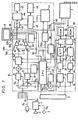
- Figure 1 is a block diagram schematically showing the circuit configuration of a surveillance system according to a preferred embodiment of the present invention;
- Figure 2 is a diagram showing a control panel of the system of Figure 1;
- Figures 3A, 3B and 3C are waveform diagrams for explaining how to set a threshold value level;
- Figure 4 is a flow chart showing a test operation of the system of Figure 1;
- Figure 5 is a flow chart showing a power supply control function in a manual mode; and
- Figure 6 is a flow chart showing a power supply control function in an auto scan mode.
- Figure 1 shows a surveillance system including a television (TV)
camera 1 which outputs a video signal Sv through a line lv to a switching circuit 11 in aswitch section 10. Amicrophone 2 is attached to thetelevision camera 1. A signal Ss (a direct current (DC) signal) detected and outputted from aknown sensor 3 using infra-red rays or the like is superimposed on an audio signal SA outputted from themicrophone 2 by asuperimposing circuit 4. An output signal from thesuperimposing circuit 4 is supplied to theswitch section 10 through a line la. In theswitch section 10, the audio signal SA from themicrophone 3 is supplied to aswitching circuit 12 and the DC detected signal Ss is supplied to an alarm input terminal of a central processing unit (CPU) 13. - Figure 1 shows only one set of sensors including the
TV camera 1, themicrophone 2 and thesensor 3, for one channel. However, eight such sets are provided, one for each of eight channels, the sets being connected to theswitch section 10 in the same manner as described above. Therefore, the switching circuit 11 is supplied in parallel with video signals Sv delivered from eightrespective TV cameras 1 placed at different locations, theswitching circuit 12 is supplied in parallel with audio signals SA delivered from eightrespective microphones 2, and theCPU 13 is supplied in parallel at its alarm input terminal with detecting signals Ss delivered from eightrespective sensors 3. - Changing over of the
switching circuits 11 and 12 is controlled by theCPU 13 according to operation by a user of acontrol panel 5 shown in more detail in Figure 2. If one of a set ofchannel selecting switches 71 to 78 on thecontrol panel 5 is selectively pressed, theswitching circuits 11 and 12 are manually changed over (switched) to a selected channel. If anautomatic scanning switch 51 on thecontrol panel 5 is pressed, theswitching circuits 11 and 12 are sequentially changed over (switched) to different channels with a period set by sliding a scan speed setting lever 52 (e.g. 1 to 60 seconds). Selection of the channels that are to be sequentially changed over or switched (auto scan channels) is effected as follows. First, theauto scan switch 51 is left in a depressed state, in which switching portions of the respectivechannel selecting switches 71 to 78 are repeatedly lit and extinguished (blink). Then, thechannel selecting switches 71 to 78 for those channels which are to be sequentially changed over (switched) are pressed in sequence, whereupon the switching portions thereof are illuminated. After this, theauto scan switch 51 is released from the depressed state, whereby the or each channel corresponding to an illuminated channel selecting switch is selected as an auto scan monitor channel. - It is not possible to select a channel whose function is set to an OFF state by a function selecting switch, as will be described later.
- Referring again to Figure 1, the video signal Sv outputted from the switching circuit 11 is supplied to an
adder circuit 14. Theadder circuit 14 is supplied with character signals, representative of date, time, and channel, which are generated by acharacter signal generator 15 under the control of theCPU 13, so that these character signals are added to the video signal Sv. Then, the composite video signal Sv including the character signals is supplied through agate circuit 16 to a fixed terminal A of a change-over switch orcircuit 17. Another fixed terminal B of the change-over switch 17 is supplied with a video signal Sv' from an external video signal input terminal 18V. One of the video signals Sv and Sv' selected by the change-overswitch 17 is supplied to a videosignal output terminal 20V through anamplifier 19. - The audio signal SA outputted from the
switching circuit 12 is supplied to a fixed terminal A of a change-over switch orcircuit 21. An audio signal SA' from an external audiosignal input terminal 18A is supplied to another fixed terminal B of the change-overswitch 21. One of the audio signals SA and SA' from the change-overswitch 21 is supplied to an audiosignal output terminal 20A through anamplifier 22. The video signal and audio signal outputted from theamplifiers monitoring apparatus 6. - Changing over (switching) of the change-
over switches CPU 13 according to operation by the user of thecontrol panel 5. For example, theswitches external selection switch 53 shown in Figure 2. When theswitches monitoring apparatus 6 and sound from the audio signal SA is generated by a loudspeaker of themonitoring apparatus 6. On the other hand, when theswitches monitoring apparatus 6 and sound from the audio signal SA' is generated by the loudspeaker of themonitoring apparatus 6. - The video signal Sv from each of the eight TV cameras is supplied through an
adder circuit 23 to adigitiser circuit 31 and a synchronisingsignal separating circuit 32 in an image processing section orcircuit 30. A digital output video signal Sv2 produced by thedigitiser circuit 31 is supplied to aswitching circuit 33, and a synchronising signal Ssync separated from the video signal Sv by the synchronisingsignal separating circuit 32 is supplied to aswitching circuit 34. Switching of theswitching circuits CPU 35. - Among the eight channels, those channels which are selected to be sequentially changed over are defined as sensing channels, which means a channel in which a scene change can be detected by selecting a PRINT or ALARM functional mode or function. Selection of the function for each channel is effected by function selecting sliding
switches 91 to 98 arranged on thecontrol panel 5 as shown in Figure 2. Theswitches 91 to 98 enable selection of the PRINT function, the ALARM function, a MONITOR function or the above-mentioned OFF function. Selection of the PRINT function causes an alarm to be generated and the image from the channel in question to be printed out when a change in a scene is detected by theimage processing section 30. Selection of the ALARM function causes an alarm to be generated when a change in a scene is detected by theimage processing section 30. When the MONITOR function is selected, theimage processing section 30 does not detect changes in a scene as mentioned above, so that neither generation of an alarm nor printing out of an image of the channel in question takes place. The changing over of theswitching circuits - The video signal Sv2 from the
switching circuit 33 is supplied to a serial-to-parallel converting circuit 36 comprising, for example, a shift register. The synchronising signal Ssync from theswitching circuit 34 is supplied to anaddress comparator 37 in which a location address is generated from the synchronising signal Ssync and then compared with an assigned location address supplied to theaddress comparator 37 from theCPU 35. When the location address coincides with the assigned location address, a coincidence pulse Po is supplied from theaddress comparator 37 to the convertingcircuit 36 to halt a shifting operation effected by the convertingcircuit 36, and data stored in the shift register thereby is written into a random access memory (RAM) 38 at a predetermined address as parallel data, under the control of theCPU 35. The assigned location address from theCPU 35 is sequentially changed so as to write the data into the RAM 38. Reference data corresponding to the video signal Sv2 when no change is detected in a scene is previously stored in theRAM 38. - The operation described above is effected for each of the sensing channels. For each of the sensing channels, the
CPU 35 compares the reference data with current data which is sequentially written into theRAM 38 afterwards. If a change of more than a predetermined amount is detected, a scene change alarm output signal SAL is delivered from theCPU 35. The scene change alarm output signal SAL may, for example, be a 4-bit signal comprising three bits of channel data and one bit of alarm data. TheCPU 35 is operated by a program stored in a read only memory (ROM) 39. - The alarm signal SAL from the
CPU 35 is supplied to an alarm input terminal of theCPU 13. When theCPU 13 is supplied with the alarm output signal SAL, theCPU 13 delivers a signal Sc which drives analarm generating circuit 24 comprising a buzzer or a lamp. The signal Sc is also supplied to an externalalarm output terminal 25. - When the alarm output signal SAL is supplied to the
CPU 13, the switchingcircuits 11 and 12 are changed over to the corresponding channel by theCPU 13, and the change-overswitches CPU 13 if they previously were connected to their respective terminals B. Then, themonitoring apparatus 6 displays on its screen an image reproduced from the image signal Sv supplied from the corresponding channel. Further, a printer trigger signal STR is generated by theCPU 13 and supplied through atrigger control circuit 26 to a CPU 41 which is provided in aprinter section 40. When the CPU 41 is supplied with the trigger signal STR, amemory control circuit 42 of theprinter section 40 is controlled by the CPU 41 and the signal Sv from the corresponding channel is converted into a digital signal by an analogue-to-digital (A/D)converter 43 and signals corresponding to one field of the converted signal Sv are then written into avideo memory 44 under the control of thememory control circuit 42. Then, data is sequentially read from thevideo memory 44, under the control of thememory control circuit 42, and supplied to a printer head 45. At the same time, aprinter motor 46 is driven to print an image of the corresponding channel. I - The
video memory 44 comprises storage with a capacity of, for example, four field memories. Therefore, even if four trigger signals STR are successively supplied to the CPU 41, one field of the respective video signals Sv of the corresponding channels can be written into thevideo memory 44. When four field memories are all in use and a current printing operation is not terminated, a printer busy signal SpB is generated by the CPU 41 and then supplied to thetrigger control circuit 26 to inhibit the circuit so as not to supply the trigger signal STR therefrom to the CPU 41. - The above description assumes that the
CPU 13 is supplied with the alarm output signal SAL. However, the same operation is effected when a change in a scene is detected by the detected signal Ss. - In order that the
image processing section 30 will operate correctly, it is necessary to set correctly a threshold value level EO for thedigitiser circuit 31 in theimage processing section 30 corresponding to a value of the level of the video signal Sv delivered from theTV camera 1 of each channel. When the video signal Sv is at a level indicated by a solid line in Figure 3A, the threshold value level Eo may be set to an approximately central value of a range of the video signal Sv, as shown by a broken line in Figure 3A. Then, the video signal Sv2 delivered from thedigitiser circuit 31 has a waveform as shown in Figure 2B. The threshold value level EO is set for each of the channels, as is hereinafter explained. - First, a SETTING mode is selected by means of a sliding
switch 54 on thecontrol panel 5 shown in Figure 2. At this time, the change-over switches orcircuits CPU 13 and themonitoring apparatus 6 is supplied with the video signal Sv through thegate circuit 16 to display an image reproduced from this video signal Sv on the screen thereof. - Next, a channel for which the threshold value level Eo is set is selected by pressing one of the
channel selecting switches 71 to 78. At this time, the switchingcircuits 11 and 12 in theswitch section 10 and the switchingcircuits image processing section 30 are respectively changed over to the selected channel, under the control of theCPU 13. - In the operation described above, the
gate circuit 16 is controlled by theCPU 13 so as to gate the video signal Sv from theadder circuit 14 by use of the digitised video signal Sv2 derived from the switchingcircuit 33. For example, when the apparatus is operating in a normal condition, thegate circuit 16 is controlled such that it allows the video signal Sv delivered from theadder circuit 14 to pass therethrough unmodified. Therefore, when the video signal Vs from theadder circuit 14 has a waveform as indicated by the solid line in Figure 3A, while the video signal Sv2 from the switchingcircuit 33 has a waveform as shown in Figure 3B, the video signal Sv having a waveform as shown in Figure 3C is outputted from thegate circuit 16 and supplied to themonitoring apparatus 6 which displays an image reproduced from such video signal Sv on the screen thereof. - Next, if the threshold value level Eo for each channel is adjusted by rotating
knobs 81 to 88 arranged on thecontrol panel 5, for setting the threshold value Eg for corresponding channels, the video signal Sv2 is changed, which causes a change in the video signal Sv from thegate circuit 16, and thereby an image on the screen of themonitoring apparatus 6 also is changed. Thus, the operator adjusts the threshold value level Eo, as shown by the broken line in Figure 3A, while monitoring the image on the screen of themonitoring apparatus 6. When the threshold value level Eg is adjusted as shown in Figure 3A, the image on the screen of themonitoring apparatus 6 is such that a bright portion and a dark portion each substantially occupy half of the entire image. - Then, if an OPERATION mode is selected by means of the sliding
switch 54, the apparatus returns to the operating condition. - As described above, if a change is detected in an image delivered from a sensing channel, the alarm signal SAL is outputted from the
image processing section 30 to generate an alarm from thealarm generating circuit 24, or the image from that channel is printed out. However, it is necessary to check or test whether theimage processing section 30 is operating normally. According to the present embodiment, the surveillance apparatus is so constructed that theimage processing section 30 can be manually or automatically checked. - A description of how the
image processing section 30 is manually checked will now be given. First, atest switch 55 on thecontrol panel 5 is pressed, whereby anoise generating circuit 27 is activated by theCPU 13 and noise (a noise signal) SN generated thereby is added by theadder circuit 23 to the video signal Sv delivered from theTV camera 1 of each of the respective eight channels, and then the output signal from theadder circuit 23 is supplied to thedigitiser circuit 31. Further, the switchingcircuits 11 and 12 in theswitch section 10 and the switchingcircuits image processing section 30 are respectively changed over, with a predetermined cyclic period, sequentially from one of the sensing channels to another, in synchronism. - Adding the noise SN to the video signal Sv results in a quasi- change in a scene. Therefore, if the
image processing section 30 is operating correctly or normally, the alarm output signal SAL should be outputted from theCPU 35, as described above. If, however, theimage processing section 30 is not operating correctly, the alarm output signal SAL is not outputted from theCPU 35. - Further, when the
test switch 55 on thecontrol panel 5 is pressed, the change-overswitches CPU 13. Also, every time each of the sensing channels is sequentially changed over, theCPU 13 supplies the printer trigger signal STR through thetrigger control circuit 28 to the CPU 41 of theprinter section 40, and the charactersignal generating circuit 15 generates, in addition to character signals representative of the date, time and channel, character signals representative of "OK" when the alarm signal SAL is outputted, or character signals representative of "NG" when the alarm signal SAL is not outputted. The character signals are added to the video signal Sv by theadder circuit 14. Therefore, corresponding to each of the sensing channels, themonitoring apparatus 6 displays an image with "OK" or "NG" superimposed thereon, and theprinter section 40 prints the image with "OK" or "NG" superimposed thereon. When the above-mentioned checking operation is terminated for all of the sensing channels, the system returns to the normal operating condition. - If "NG" is displayed, the
image processing section 30 is not operating correctly for the corresponding channel, so that the threshold value level EO for this channel, applied to thedigitiser circuit 31, has to be set again in the same manner as described above. - In the case of automatic testing, the same operation as performed in the above-described manual test is automatically effected at predetermined time intervals, for example every 10 days.
- Figure 4 is a flow chart generally showing the operation effected by the embodiment of the present invention shown in Figure 1, including the above-mentioned manual and automatic tests. When the embodiment shown in Figure 1 is operated by a timer, it may be that the power supply is turned off at the time that the automatic test is about to start. In that event, the power supply is turned on before the automatic test starts and turned off again when the automatic test is completed, as shown in Figure 4.
- Referring again to Figure 1, a
power supply circuit 7 supplies required electrical power to theswitch section 10, theimage processing section 30 and theprinter section 40. TheTV cameras 1 in the eight channels are supplied with electrical power through a powersupply control circuit 28 arranged in theswitch section 10. The powersupply control circuit 28 is controlled by theCPU 13 to control the supply of power to theTV cameras 1 in the eight channels as follows. When the power supply is turned on, all theTV cameras 1 in the eight channels are supplied with electrical power. Then, it is determined whether or not there is a channel in which the TV camera is not connected, by checking for the presence of a synchronising signal. Next, electrical power is supplied to theTV cameras 1 of all the channels which are not left in the OFF mode by thefunction selecting switches TV camera 1 connected therewith, and simultaneously the channel having the smallest or lowest number is determined as the selected channel (manual mode). If none of thechannel selecting switches 71 to 78 is depressed within a predetermined time period (for example 30 seconds) in this state, the power supply is halted for all of theTV cameras 1 except for the TV cameras of the lowest-numbered channel and the sensing channels. On the other hand, if one of thechannel selecting switches 71 to 78 is depressed within the predetermined time period, the measured time is cleared and measurement of the time is started again from the time at which the switch was depressed. If none of thechannel selecting switches 71 to 78 is depressed within a predetermined time period (for example 30 seconds) after depression of thechannel selecting switches 71 to 78, the power supply is halted for all of theTV cameras 1 except for the TV cameras of the selected channels and the sensing channels. If one of thechannel selecting switches 71 to 78 is depressed after the predetermined time period has elapsed, electrical power is again supplied to theTV cameras 1 of all the channels which are not left in the OFF mode by thefunction selecting switches 91 to 98 and have aTV camera 1 connected therewith, and an operation similar to that mentioned above is carried out. Figure 5 is a flow chart showing the above-described operation. - When the
auto scan switch 51 is pressed (the auto scan mode), the power supply is halted for theTV cameras 1 except for those in the auto scan channel and sensing channels. Figure 6 is a flow chart showing this operation. - The
monitoring apparatus 6 is supplied with electrical power from the powersupply control circuit 28. - Referring again to Figure 2, the
control panel 5 has apower supply switch 56, aswitch 57 for feeding theprinter section 40 with paper on which images are printed, aswitch 58 for printing an image reproduced from the video signal then supplied to theprinter section 40, aswitch 59 for printing an image reproduced from the video signal stored in thevideo memory 44, aswitch 60 for turning on and off the automatic printing function at the time when the alarm signal SAL is outputted or the like, aswitch 61 for turning on and off the timer operation, aswitch 62 for turning on and off thealarm generating circuit 24, alight emitting diode 63 which constitutes thealarm generating circuit 24, alever 64 for adjusting, for example, a volume of the buzzer which also constitutes thealarm generating circuit 24, agroup 65 of switches for determining a range in which changes in scene are detected, and agroup 66 of switches for setting the time of the timer. - As described above, the present embodiment automatically checks at predetermined intervals, for example every 10 days, whether or not the
image processing section 30 is operating normally, so that proper operation of theimage processing section 30 can be ensured, rendering it possible to provide a surveillance system with high accuracy. Further, while theimage processing section 30 is thus automatically checked, theprinter section 40 is in operating condition. Therefore, a check is made simultaneously as to whether or not theprinter section 40 is operating normally, which is another advantage of the embodiment. - Further, according to the present embodiment, a user can freely set the change-over cyclic period of the switching
circuits 11 and 12 of theswitch section 10 by means of an operatingknob 52 on thecontrol panel 5, independently of the change-over cyclic period of the switchingcircuits image processing section 30, which gives facility in operation to users. When the alarm signal SAL is outputted from theimage processing section 30, the switchingcircuits 11 and 12 are respectively changed over to a corresponding channel, and themonitoring apparatus 6 displays an image from this channel on its screen, so that no problem will occur as a result of abnormal conditions of these switches. - Furthermore, according to the present embodiment, the electrical power supplied to the
TV cameras 1 is controlled by the powersupply control circuit 28 so as to halt the power supply to unused TV cameras, which results in largely reducing the power consumption as well as prolonging the effective life of theTV cameras 1, and particularly the image pick-up devices arranged therein. - Still further, in the manual mode, all the
TV cameras 1 are supplied with electrical power for a predetermined period of time, for example 30 seconds. Therefore, if one of the other channels is selected within this predetermined period of time, the image on the screen can be prevented from deterioration due to initial unstable conditions and so on, whereby users will not suffer the unpleasant viewing of initial conditions.
Claims (5)
Applications Claiming Priority (2)
| Application Number | Priority Date | Filing Date | Title |
|---|---|---|---|
| JP109270/86 | 1986-05-13 | ||
| JP61109270A JPS62265878A (en) | 1986-05-13 | 1986-05-13 | Monitor device |
Publications (3)
| Publication Number | Publication Date |
|---|---|
| EP0246085A2 true EP0246085A2 (en) | 1987-11-19 |
| EP0246085A3 EP0246085A3 (en) | 1989-03-22 |
| EP0246085B1 EP0246085B1 (en) | 1993-03-10 |
Family
ID=14505914
Family Applications (1)
| Application Number | Title | Priority Date | Filing Date |
|---|---|---|---|
| EP87304251A Expired - Lifetime EP0246085B1 (en) | 1986-05-13 | 1987-05-13 | Surveillance systems |
Country Status (5)
| Country | Link |
|---|---|
| US (1) | US4772945A (en) |
| EP (1) | EP0246085B1 (en) |
| JP (1) | JPS62265878A (en) |
| CA (1) | CA1271248A (en) |
| DE (1) | DE3784551T2 (en) |
Cited By (2)
| Publication number | Priority date | Publication date | Assignee | Title |
|---|---|---|---|---|
| WO2004045912A1 (en) * | 2002-11-16 | 2004-06-03 | Robert Bosch Gmbh | Image generator |
| DE10341426A1 (en) * | 2003-09-09 | 2005-04-14 | Fraunhofer-Gesellschaft zur Förderung der angewandten Forschung e.V. | Area e.g. railway station platform, monitoring method, monitors defined areas to detect situations which are then classified according to type and location by using video camera signal analysis |
Families Citing this family (25)
| Publication number | Priority date | Publication date | Assignee | Title |
|---|---|---|---|---|
| JPH01181389A (en) * | 1988-01-14 | 1989-07-19 | Hitachi Ltd | Image processing device |
| US4963961A (en) * | 1989-06-16 | 1990-10-16 | Burle Technologies, Inc. | Vertical motion detector |
| US5065251A (en) * | 1989-07-28 | 1991-11-12 | Shuhart Jr Harvey A | Method and apparatus for graphically marking an audiovisual recording to indicate occurrence of an official's whistle signal |
| KR920005058B1 (en) * | 1989-12-15 | 1992-06-26 | 주식회사 금성사 | 4-screen display |
| US5008745A (en) * | 1989-12-21 | 1991-04-16 | Burle Technologies, Inc. | Clock synchronized digital TV motion detector |
| US5103254A (en) * | 1990-05-29 | 1992-04-07 | Eastman Kodak Company | Camera with subject highlighting and motion detection |
| US5109278A (en) * | 1990-07-06 | 1992-04-28 | Commonwealth Edison Company | Auto freeze frame display for intrusion monitoring system |
| WO1992010908A2 (en) * | 1990-12-14 | 1992-06-25 | Battelle Memorial Institute | High-speed video instrumentation system |
| WO1993013878A1 (en) * | 1992-01-08 | 1993-07-22 | Connolly Joseph W | Color detection and separation method |
| JPH06153202A (en) * | 1992-10-29 | 1994-05-31 | F M T:Kk | Abnormality monitoring device |
| USRE43462E1 (en) | 1993-04-21 | 2012-06-12 | Kinya (Ken) Washino | Video monitoring and conferencing system |
| US6313872B1 (en) | 1993-06-18 | 2001-11-06 | Isabelle R. Borg | Security system for homes and small offices |
| US6628887B1 (en) | 1998-04-17 | 2003-09-30 | Honeywell International, Inc. | Video security system |
| CA2195415A1 (en) * | 1994-07-26 | 1996-02-08 | Scott Anthony Rhodes | A video security system |
| US6069655A (en) * | 1997-08-01 | 2000-05-30 | Wells Fargo Alarm Services, Inc. | Advanced video security system |
| US7061522B1 (en) * | 1998-03-18 | 2006-06-13 | The Furukawa Electric Co., Ltd. | Optical fiber fusion-splicer |
| US6462774B1 (en) * | 1999-12-20 | 2002-10-08 | Dale Bildstein | Surveillance system method and apparatus |
| JP4110946B2 (en) * | 2002-11-26 | 2008-07-02 | ソニー株式会社 | IMAGING DEVICE AND IMAGING DEVICE PRINTING METHOD |
| US7504965B1 (en) | 2005-08-05 | 2009-03-17 | Elsag North America, Llc | Portable covert license plate reader |
| WO2008128140A1 (en) * | 2007-04-13 | 2008-10-23 | The Regents Of The University Of Michigan | Delivery device and method for forming the same |
| GB0709329D0 (en) | 2007-05-15 | 2007-06-20 | Ipsotek Ltd | Data processing apparatus |
| US8421478B2 (en) | 2008-01-25 | 2013-04-16 | International Business Machines Corporation | Radio frequency integrated circuit with on-chip noise source for self-test |
| US7720364B2 (en) * | 2008-01-30 | 2010-05-18 | Microsoft Corporation | Triggering data capture based on pointing direction |
| US9659237B2 (en) | 2012-10-05 | 2017-05-23 | Micro Usa, Inc. | Imaging through aerosol obscurants |
| WO2021102483A2 (en) * | 2020-04-15 | 2021-05-27 | Zeku, Inc. | Method and apparatus for operating a companion processing unit |
Family Cites Families (11)
| Publication number | Priority date | Publication date | Assignee | Title |
|---|---|---|---|---|
| US3740466A (en) * | 1970-12-14 | 1973-06-19 | Jackson & Church Electronics C | Surveillance system |
| AU520219B2 (en) * | 1978-08-25 | 1982-01-21 | Commercial Data Processing Ltd. | Video security alarm system |
| US4257063A (en) * | 1979-03-23 | 1981-03-17 | Ham Industries, Inc. | Video monitoring system and method |
| US4337481A (en) * | 1980-06-10 | 1982-06-29 | Peter Mick | Motion and intrusion detecting system |
| AU537554B2 (en) * | 1980-10-22 | 1984-06-28 | Commonwealth Of Australia, The | Video movement detector |
| JPS5947694A (en) * | 1982-09-10 | 1984-03-17 | ニツタン株式会社 | Sensor testing circuit for alarm |
| US4511886A (en) * | 1983-06-01 | 1985-04-16 | Micron International, Ltd. | Electronic security and surveillance system |
| GB2150724A (en) * | 1983-11-02 | 1985-07-03 | Christopher Hall | Surveillance system |
| US4630110A (en) * | 1984-02-15 | 1986-12-16 | Supervision Control Systems, Inc. | Surveillance system |
| US4679077A (en) * | 1984-11-10 | 1987-07-07 | Matsushita Electric Works, Ltd. | Visual Image sensor system |
| JPS61166289A (en) * | 1985-01-18 | 1986-07-26 | Hitachi Ltd | Picture transmission system |
-
1986
- 1986-05-13 JP JP61109270A patent/JPS62265878A/en active Pending
-
1987
- 1987-05-11 US US07/048,618 patent/US4772945A/en not_active Expired - Fee Related
- 1987-05-12 CA CA000536910A patent/CA1271248A/en not_active Expired
- 1987-05-13 EP EP87304251A patent/EP0246085B1/en not_active Expired - Lifetime
- 1987-05-13 DE DE8787304251T patent/DE3784551T2/en not_active Expired - Fee Related
Cited By (5)
| Publication number | Priority date | Publication date | Assignee | Title |
|---|---|---|---|---|
| WO2004045912A1 (en) * | 2002-11-16 | 2004-06-03 | Robert Bosch Gmbh | Image generator |
| WO2004045911A1 (en) * | 2002-11-16 | 2004-06-03 | Robert Bosch Gmbh | Image generator |
| CN100360346C (en) * | 2002-11-16 | 2008-01-09 | 罗伯特-博希股份公司 | Video signal generator |
| US7619650B2 (en) | 2002-11-16 | 2009-11-17 | Robert Bosch Gmbh | Imaging sensor that monitors operability of the imaging sensor |
| DE10341426A1 (en) * | 2003-09-09 | 2005-04-14 | Fraunhofer-Gesellschaft zur Förderung der angewandten Forschung e.V. | Area e.g. railway station platform, monitoring method, monitors defined areas to detect situations which are then classified according to type and location by using video camera signal analysis |
Also Published As
| Publication number | Publication date |
|---|---|
| US4772945A (en) | 1988-09-20 |
| JPS62265878A (en) | 1987-11-18 |
| DE3784551D1 (en) | 1993-04-15 |
| DE3784551T2 (en) | 1993-08-12 |
| EP0246085A3 (en) | 1989-03-22 |
| EP0246085B1 (en) | 1993-03-10 |
| CA1271248A (en) | 1990-07-03 |
Similar Documents
| Publication | Publication Date | Title |
|---|---|---|
| EP0246085B1 (en) | Surveillance systems | |
| CA1300745C (en) | Electronic still camera with indicator for number of tracks available for video and/or audio recording | |
| US4727417A (en) | Endoscope video apparatus | |
| US5671009A (en) | CCTV system having improved detection function and detecting method suited for the system | |
| KR910006609B1 (en) | Electronic still camera | |
| KR100200616B1 (en) | Display device for watching-screen dividing and method therefor | |
| US4802018A (en) | Electronic marking apparatus for identifying a selected image from a plurality of electronically stored images | |
| US5032926A (en) | Video tape recorder having picture-in-picture function | |
| GB2252194A (en) | Automatic copying in video recorder apparatus | |
| US5457542A (en) | Caption display apparatus for VCR | |
| US5177615A (en) | Apparatus for recovering a film signal from a television video signal | |
| EP0256380B1 (en) | Magnetic recording apparatus | |
| JP2550946B2 (en) | Monitoring device | |
| GB2226732A (en) | Television surveillance system | |
| JPH07114489B2 (en) | Monitoring device | |
| KR930012202B1 (en) | Device for checking video record conditions | |
| KR100529135B1 (en) | Self diagnosis method in a single unit timelapse image recording and reproducing apparatus | |
| KR0174040B1 (en) | Surveillance System | |
| KR0143022B1 (en) | Apparatus of automatic tape searching | |
| KR0137264B1 (en) | Display device of multiplexed video signal | |
| EP0512105B1 (en) | Telephoto sensor trigger in a solid state motion analysis system | |
| JP3249402B2 (en) | Video signal processing device and video playback device | |
| KR900005066B1 (en) | Program reproducing circuit due to the signal source of broadcasting information | |
| GB2126460A (en) | Video response testing apparatus | |
| JPH0998317A (en) | Automatic angle of view monitoring device |
Legal Events
| Date | Code | Title | Description |
|---|---|---|---|
| PUAI | Public reference made under article 153(3) epc to a published international application that has entered the european phase |
Free format text: ORIGINAL CODE: 0009012 |
|
| AK | Designated contracting states |
Kind code of ref document: A2 Designated state(s): DE FR GB NL |
|
| PUAL | Search report despatched |
Free format text: ORIGINAL CODE: 0009013 |
|
| AK | Designated contracting states |
Kind code of ref document: A3 Designated state(s): DE FR GB NL |
|
| 17P | Request for examination filed |
Effective date: 19890814 |
|
| 17Q | First examination report despatched |
Effective date: 19910604 |
|
| GRAA | (expected) grant |
Free format text: ORIGINAL CODE: 0009210 |
|
| AK | Designated contracting states |
Kind code of ref document: B1 Designated state(s): DE FR GB NL |
|
| REF | Corresponds to: |
Ref document number: 3784551 Country of ref document: DE Date of ref document: 19930415 |
|
| PGFP | Annual fee paid to national office [announced via postgrant information from national office to epo] |
Ref country code: FR Payment date: 19930526 Year of fee payment: 7 |
|
| PGFP | Annual fee paid to national office [announced via postgrant information from national office to epo] |
Ref country code: NL Payment date: 19930531 Year of fee payment: 7 |
|
| PGFP | Annual fee paid to national office [announced via postgrant information from national office to epo] |
Ref country code: GB Payment date: 19930609 Year of fee payment: 7 |
|
| ET | Fr: translation filed | ||
| PGFP | Annual fee paid to national office [announced via postgrant information from national office to epo] |
Ref country code: DE Payment date: 19930729 Year of fee payment: 7 |
|
| PLBE | No opposition filed within time limit |
Free format text: ORIGINAL CODE: 0009261 |
|
| STAA | Information on the status of an ep patent application or granted ep patent |
Free format text: STATUS: NO OPPOSITION FILED WITHIN TIME LIMIT |
|
| 26N | No opposition filed | ||
| PG25 | Lapsed in a contracting state [announced via postgrant information from national office to epo] |
Ref country code: GB Effective date: 19940513 |
|
| PG25 | Lapsed in a contracting state [announced via postgrant information from national office to epo] |
Ref country code: NL Effective date: 19941201 |
|
| GBPC | Gb: european patent ceased through non-payment of renewal fee |
Effective date: 19940513 |
|
| NLV4 | Nl: lapsed or anulled due to non-payment of the annual fee | ||
| PG25 | Lapsed in a contracting state [announced via postgrant information from national office to epo] |
Ref country code: FR Effective date: 19950131 |
|
| PG25 | Lapsed in a contracting state [announced via postgrant information from national office to epo] |
Ref country code: DE Effective date: 19950201 |
|
| REG | Reference to a national code |
Ref country code: FR Ref legal event code: ST |