EP0244943A1 - Electric storage battery - Google Patents
Electric storage battery Download PDFInfo
- Publication number
- EP0244943A1 EP0244943A1 EP87302762A EP87302762A EP0244943A1 EP 0244943 A1 EP0244943 A1 EP 0244943A1 EP 87302762 A EP87302762 A EP 87302762A EP 87302762 A EP87302762 A EP 87302762A EP 0244943 A1 EP0244943 A1 EP 0244943A1
- Authority
- EP
- European Patent Office
- Prior art keywords
- collars
- plate
- lug
- lugs
- aligned
- Prior art date
- Legal status (The legal status is an assumption and is not a legal conclusion. Google has not performed a legal analysis and makes no representation as to the accuracy of the status listed.)
- Granted
Links
Images


Classifications
-
- H—ELECTRICITY
- H01—ELECTRIC ELEMENTS
- H01M—PROCESSES OR MEANS, e.g. BATTERIES, FOR THE DIRECT CONVERSION OF CHEMICAL ENERGY INTO ELECTRICAL ENERGY
- H01M10/00—Secondary cells; Manufacture thereof
- H01M10/04—Construction or manufacture in general
- H01M10/0413—Large-sized flat cells or batteries for motive or stationary systems with plate-like electrodes
-
- H—ELECTRICITY
- H01—ELECTRIC ELEMENTS
- H01M—PROCESSES OR MEANS, e.g. BATTERIES, FOR THE DIRECT CONVERSION OF CHEMICAL ENERGY INTO ELECTRICAL ENERGY
- H01M10/00—Secondary cells; Manufacture thereof
- H01M10/06—Lead-acid accumulators
- H01M10/12—Construction or manufacture
-
- H—ELECTRICITY
- H01—ELECTRIC ELEMENTS
- H01M—PROCESSES OR MEANS, e.g. BATTERIES, FOR THE DIRECT CONVERSION OF CHEMICAL ENERGY INTO ELECTRICAL ENERGY
- H01M50/00—Constructional details or processes of manufacture of the non-active parts of electrochemical cells other than fuel cells, e.g. hybrid cells
- H01M50/50—Current conducting connections for cells or batteries
- H01M50/528—Fixed electrical connections, i.e. not intended for disconnection
-
- H—ELECTRICITY
- H01—ELECTRIC ELEMENTS
- H01M—PROCESSES OR MEANS, e.g. BATTERIES, FOR THE DIRECT CONVERSION OF CHEMICAL ENERGY INTO ELECTRICAL ENERGY
- H01M50/00—Constructional details or processes of manufacture of the non-active parts of electrochemical cells other than fuel cells, e.g. hybrid cells
- H01M50/50—Current conducting connections for cells or batteries
- H01M50/531—Electrode connections inside a battery casing
- H01M50/533—Electrode connections inside a battery casing characterised by the shape of the leads or tabs
-
- H—ELECTRICITY
- H01—ELECTRIC ELEMENTS
- H01M—PROCESSES OR MEANS, e.g. BATTERIES, FOR THE DIRECT CONVERSION OF CHEMICAL ENERGY INTO ELECTRICAL ENERGY
- H01M50/00—Constructional details or processes of manufacture of the non-active parts of electrochemical cells other than fuel cells, e.g. hybrid cells
- H01M50/50—Current conducting connections for cells or batteries
- H01M50/531—Electrode connections inside a battery casing
- H01M50/54—Connection of several leads or tabs of plate-like electrode stacks, e.g. electrode pole straps or bridges
-
- Y—GENERAL TAGGING OF NEW TECHNOLOGICAL DEVELOPMENTS; GENERAL TAGGING OF CROSS-SECTIONAL TECHNOLOGIES SPANNING OVER SEVERAL SECTIONS OF THE IPC; TECHNICAL SUBJECTS COVERED BY FORMER USPC CROSS-REFERENCE ART COLLECTIONS [XRACs] AND DIGESTS
- Y02—TECHNOLOGIES OR APPLICATIONS FOR MITIGATION OR ADAPTATION AGAINST CLIMATE CHANGE
- Y02E—REDUCTION OF GREENHOUSE GAS [GHG] EMISSIONS, RELATED TO ENERGY GENERATION, TRANSMISSION OR DISTRIBUTION
- Y02E60/00—Enabling technologies; Technologies with a potential or indirect contribution to GHG emissions mitigation
- Y02E60/10—Energy storage using batteries
-
- Y—GENERAL TAGGING OF NEW TECHNOLOGICAL DEVELOPMENTS; GENERAL TAGGING OF CROSS-SECTIONAL TECHNOLOGIES SPANNING OVER SEVERAL SECTIONS OF THE IPC; TECHNICAL SUBJECTS COVERED BY FORMER USPC CROSS-REFERENCE ART COLLECTIONS [XRACs] AND DIGESTS
- Y02—TECHNOLOGIES OR APPLICATIONS FOR MITIGATION OR ADAPTATION AGAINST CLIMATE CHANGE
- Y02P—CLIMATE CHANGE MITIGATION TECHNOLOGIES IN THE PRODUCTION OR PROCESSING OF GOODS
- Y02P70/00—Climate change mitigation technologies in the production process for final industrial or consumer products
- Y02P70/50—Manufacturing or production processes characterised by the final manufactured product
Definitions
- This invention relates to plates (i.e., electrodes) and cell elements for electric storage batteries.
- Electric storage batteries (such as, e.g., lead-acid, or nickel zinc (Ni-Zn)) comprise several galvanic cell elements each immersed in an electrolyte and encased in a separate compartment of a substantially leak-proof container.
- Each cell element comprises at least one plate-like, positive electrode (i.e., a positive plate), one plate-like negative electrode (i.e., negative plate) and a porous separator (e.g., a thin microporous sheet and/or absorbent glass mat) therebetween.
- Multi-plate cell elements are commonplace and comprise a stack of alternating positive and negative polarity plates interleaved one with the other and the separators.
- the plates themselves each comprise a conductive substrate which supports an electrochemically-active material thereon and conducts electrical current substantially uniformly therethrough.
- the plates comprise a leady active material (i.e., lead dioxide (PbO2) for the positive plates and lead (Pb) for the negative plates) pasted onto a reticulated Pb-alloy grid substrate.
- a lug projects from the substrate/grid of each plate and serves to electrically couple the plate to other electrical components (e.g., terminals, or other plates) of the battery.
- One such coupling occurs between aligned lugs of like polarity plates within a multi-plate cell element and thence, via an intercell connector, to opposite polarity plates in adjacent cells.
- the lugs are coupled by simply bundling and welding the plates and lugs together through an aperture in an intercell partition of the container such as shown in Figure 5 of US-A-4,046,062. More typically, however, the plate lugs are electrically coupled one to the other by a bus bar, known as a plate strap, which is burned to, or cast about, the plate lugs: (1) inside the battery container such as disclosed in Figure 2 of the aforesaid US-A-4,046,062; or (2) outside the battery container such, for example, as disclosed in US-A-3,841,915, where the plate strap is formed in the cover of the container.
- a bus bar known as a plate strap
- the present invention comprehends a battery plate having: a conductive substrate supporting an electrochemically-active material; a lug projecting from the substrate to electrically couple the plate to other electrical component(s) (e.g., plates and terminals) of the battery; and a discrete, insulating collar formed tightly about the root (i.e., proximate the substrate) of each lug, which collar is adapted to engage collars on other lugs, and/or an aperture in the container wall of the battery to form a substantially liquid-tight seal therewith or otherwise to facilitate various battery assembly operations.
- a battery plate having: a conductive substrate supporting an electrochemically-active material; a lug projecting from the substrate to electrically couple the plate to other electrical component(s) (e.g., plates and terminals) of the battery; and a discrete, insulating collar formed tightly about the root (i.e., proximate the substrate) of each lug, which collar is adapted to engage collars on other lugs, and/or an
- a battery cell element is formed from a plurality of lug-bearing, positive and negative polarity plates alternately interleaved with one another wherein each plate lug has a discrete insulating (e.g., thermoplastic or thermosetting resin) collar formed about the root thereof (i.e., near the active material of the plate).
- the collar on each lug is aligned in abutting relation to other collars on other lugs of like polarity plates in the element and together therewith serve (1) to space the lugs apart, (2) to insulate the electrical connector of the lug from plates of opposite polarity, and (3), in some instances, to form a mould for forming a plate strap, in situ, about the plate lugs.
- each lug engages an electrical connector (e.g., plate strap) which electrically couples the plate lugs together.
- an electrical connector e.g., plate strap
- Each collar will most preferably have a U-shaped configuration, the legs of which extend up along the edges of the distal portion of its associated lug and, when aligned and abutted to other collars, forms a trough for shaping a plate strap moulded therein.
- the separate collars may be tied together by means of a thread extending the length of the aligned collars through apertures formed therein.
- the thread will be bonded (e.g., welded) at its ends to the end collars in each stack.
- the U-shaped collars are provided with laterally-extending flanges for engaging portions of a container wall surrounding an aperture in the wall into which the collar has been fitted. A sealant applied to the flanges and the wall seals the collar in the aperture.
- Figure 1 depicts a battery cell element 1 comprising a stack of positive plates 3 interleaved with a plurality of negative plates 5 and appropriate interplate separators (not shown).
- the plates comprise an active material 7 supported on a conductive substrate, here shown as a gridwork of wires 9 joined at the top by a header 11.
- a plate lug 13 projects from each positive plate 3 and is aligned with other poistive plate lugs along one side (e.g., the top) of the cell element stack 1.
- the negative polarity plates 5 have similar plate lugs 15 thereon similarly aligned.
- a U-shaped insulating collar 17 is firmly secured to the root (i.e., adjacent the header 11) of each positive plate lug 13 and is aligned in abutting relation with similar collars on the aligned lugs 13. Similar collars 19 on the negative lugs 15 are similarly aligned. While the following description is given in conjunction with the positive plates and their associated lugs and collars, it is to be understood that the substantial content thereof applies equally to the negative plates and associated lugs/collars.
- the collars space the aligned lugs from each other and preferably comprise a synthetic thermoplastics material (e.g., polypropylene or polyphenylene sulfide,) injection-moulded directly about the lugs.
- the collars 17 preferably have a U-shaped configuration including a base portion 21 engaging the root 23 of each lug and upstanding legs 25 which flank the lateral edges 27 of distal portions 29 of the lugs which are more remote from the active material 7 of the plate.
- an appropriate coupler e.g., cast-in-place plate strap (not shown)
- the trough 31 serves as a mould to shape the molten lead cast therein.
- End plates 33 are provided at the ends of each trough 31 opposite the end where the intercell connector is to be formed and serve to prevent molten lead from spilling out of the end of the trough 31.
- Each plate lug collar 17 and end plate 33 has an aperture 35 (i.e., about 1.65 mm (0.065 inch) diameter) formed therethrough to facilitate tying the several aligned lugs together in the stack.
- the apertures 35 line up as best shown in Figures 2 and 3.
- a thread 37 e.g., 1.60 mm (0.063 inch) diameter polypropylene
- Figure 4 depicts another method of assembling a Pb-acid battery utilizing plate-lug collars in accordance with the present invention.
- a plurality of positive plates 43 are stacked together (i.e., interleaved with negative plates, not shown) to form one cell element stack 45.
- a plurality of negative plates 47 are stacked together (i.e., underleaved with positive plates, (not shown) to form another cell element 49.
- the two cell elements 45 and 49 are destined for placement in adjacent cell compartments of a battery container after being electrically joined together via an intercell connector insert 51.
- the lugs 53 of the positive plates 43 of stack 45 have polypropylene collars 55 injection-moulded about the roots 57 thereof leaving the distal portions 59 thereof disposed above the collars 55 for electrical coupling to each other by an appropriate means (e.g., plate strap).
- a plurality of negative plates 47 have their lugs 61 provided with collars 63 and are stacked together (i.e., interleaved with positive plates, not shown) to form the cell element stack 49.
- the cell elements 45 and 49 are positioned in an appropriate fixture or jig (not shown) so that the positive plate lugs 53 of element 45, the negative plate lugs 61 of element 49 and the intercell connector insert 51 are positioned as shown.
- the intercell connector insert 51 comprises an intercell connector element 65 which bridges an intercell partition of the container and flanges 67 and 69 on the opposite ends of the element 65.
- a steel mould 71 is then placed over the aligned lugs and insert.
- the mould 71 has a first moulding cavity 73 encompassing the distal ends 75 of the negative plate lugs 61 and a second moulding cavity 77 encompassing the distal ends 59 of the positive plate lugs 53 at the same time.
- the aligned and abutting lug collars 55, 63 form the bottoms of the mould cavities 73 and 77.
- Molten lead introduced into the mould cavities 73, 77 melts and fuses to the distal portions 75 and 59 of the lugs 61 and 53, respectively, as well as to the outer faces of the flanges 67 and 69 of the insert 51.
- the molten lead essentially solidifies into plate straps 79 and 81 and joins the lugs and insert together in a unified assembly which is ready for insertion into an appropriate battery container 83 (see Figure 5).
- the assembly formed as described in conjunction with Figure 4 is inserted into a battery container 83 which includes a plurality of intercell partitions 85 for separating the cell compartments one from the other.
- Each partition 85 includes a slot 87 adapted to receive the intercell connector element 65 in the manner shown in Figure 6.
- Ribs 89 are provided on the partition 85 adjacent the slot 87 and serve to engage the inside faces 91 of the flanges 67 and 69 of the intercell connector insert 51.
- the lower ends of the ribs 89 engage a shelf 93 formed (i.e., in a second moulding operation) at the bottom of the slot 87 and together therewith define a cavity 99.
- the cell elements 45 and 49 are positioned in adjacent cell compartments 95 and 97 of the container 83 so that the inside faces 91 of the insert 51 engage the ribs 89 and shelf 93 to enclose the sides of the cavity 99.
- an injection-moulding mould (not shown) is positioned over the partition 85 so as to encompass the slot 87 and flanges 67 and 69.
- Thermoplastics container material e.g., polypropylene
- Figure 7 depicts another similar method of assembling a battery utilizing the lug collars of the present invention.
- Cell elements 103 and 105 have synthetic plastics collars 107 and 109 moulded about the roots of their respective plate lugs 111 and 113.
- the sets of lugs are aligned with an intercell connector insert 115 in the same manner as described in conjunction with Figure 4.
- U-shaped pieces 117 and 119 of lead-coated copper are positioned about the lugs 111 and 113.
- a steel mould 121 is positioned about the pieces 117, 119 and insert 115.
- Molten lead is then introduced between the legs 123 and 123 ⁇ of the U-shaped pieces 117 and 119 to join the insert 115, plate lugs 111 and 113 and U-shaped pieces 117 and 119 together into a single unit 125. Thereafter the mould 121 is removed and the cell elements 103 and 105 positioned in a battery container in the manner as described in conjunction with Figure 6.
- FIG. 8 Another application of plate-lug collars in accordance with the present invention involves forming the interplate and/or intercell connectors of the battery and/or terminals on the outside of the battery container such as, for example, as shown in Figures 8 and 9.
- a battery cell element 126 is formed by interleaving a plurality of negative plates 127 with a plurality of positive plates 129 and intercell separators 131 essentially as described above.
- each negative plate 127 and positive plate 129 will have two lugs 133 and 135, respectively, for more efficient conduction of current to and from the plate.
- Individual insulating collars 137 are moulded about each negative plate lug 133.
- individual insulating collars 139 are moulded about the positive plate lugs 135.
- Each of the collars 137 and 139 has a generally U-shaped configuration including a base portion 141, legs 143 and two sets A and B of flanges 145-145 ⁇ and 147-147 ⁇ which extend laterally outward from the legs 143.
- the flange sets A and B define therebetween openings 149 and 151 which mate with a portion of the exterior wall of a battery container as will be described in more detail hereinafter.
- a battery container comprises a plurality of discrete trays 153 which nest one within the other.
- the trays 153 each include slots 155 and 157 in the external walls 159 thereof for receiving the lug collars 137 and 139, respectively, as depicted.
- the flanges of the flange sets A and B embrace the portions of the container wall 159 forming the edges of the slots 155 and 157 which are snugly received in the openings 149 and 151 between the flanges.
- the collars 137 and 139 fill and substantially plug the slots with which they are mated.
- molten lead is cast about the lugs between the legs 143 of the aligned collars 137 and 139 to form plate straps 161 in essentially the same manner as discussed above.
- the container tray 153 will be the end tray in a stack and hence will house the end cell of the battery.
- a battery terminal 163 may be provided as follows.
- the legs 143 are removed from a centre region 165 of the aligned collars.
- the ends of a Pb-coated copper strap 167 are fitted into the openings 165 in the centre region and molten lead cast between the legs 143 of the aligned collars to fuse the ends of the strap 167 to the plate straps 161 at the time of their formation.
- a stud 169 projects from the strap 167 for attachment to external circuitry.
- Figure 10 depicts a variation of the structure shown in Figure 8 wherein a lug collar 171 includes a single pair of oppositely-extending flanges 173 and 175 lying contiguous the container wall 177 and sealed thereto by plastics material 179 moulded thereabout.
Landscapes
- Chemical & Material Sciences (AREA)
- Chemical Kinetics & Catalysis (AREA)
- Electrochemistry (AREA)
- General Chemical & Material Sciences (AREA)
- Engineering & Computer Science (AREA)
- Manufacturing & Machinery (AREA)
- Connection Of Batteries Or Terminals (AREA)
Abstract
Description
- This invention relates to plates (i.e., electrodes) and cell elements for electric storage batteries.
- Electric storage batteries (such as, e.g., lead-acid, or nickel zinc (Ni-Zn)) comprise several galvanic cell elements each immersed in an electrolyte and encased in a separate compartment of a substantially leak-proof container. Each cell element comprises at least one plate-like, positive electrode (i.e., a positive plate), one plate-like negative electrode (i.e., negative plate) and a porous separator (e.g., a thin microporous sheet and/or absorbent glass mat) therebetween. Multi-plate cell elements are commonplace and comprise a stack of alternating positive and negative polarity plates interleaved one with the other and the separators. The plates themselves each comprise a conductive substrate which supports an electrochemically-active material thereon and conducts electrical current substantially uniformly therethrough. In lead (Pb)-acid batteries, for example, the plates comprise a leady active material (i.e., lead dioxide (PbO₂) for the positive plates and lead (Pb) for the negative plates) pasted onto a reticulated Pb-alloy grid substrate. A lug projects from the substrate/grid of each plate and serves to electrically couple the plate to other electrical components (e.g., terminals, or other plates) of the battery. One such coupling occurs between aligned lugs of like polarity plates within a multi-plate cell element and thence, via an intercell connector, to opposite polarity plates in adjacent cells. In some instances, the lugs are coupled by simply bundling and welding the plates and lugs together through an aperture in an intercell partition of the container such as shown in Figure 5 of US-A-4,046,062. More typically, however, the plate lugs are electrically coupled one to the other by a bus bar, known as a plate strap, which is burned to, or cast about, the plate lugs: (1) inside the battery container such as disclosed in Figure 2 of the aforesaid US-A-4,046,062; or (2) outside the battery container such, for example, as disclosed in US-A-3,841,915, where the plate strap is formed in the cover of the container.
- It has been proposed to position preformed strips of insulating material over the lugs of each set of aligned positive or negative plate lugs (e.g., see US-A-2,287,802) to facilitate manufacturing, to rigidify the stack, and/or to prevent accidental internal short-circuiting of the cell. Likewise, it has been proposed to fit a preformed trough over the plate lugs to form a mould for forming a cast-in-place plate strap onto the plate lugs and through the intercell partition (e.g., see US-A-3,988,169). Finally, our own copending European patent application No.86306756.7 which is incorporated herein by reference, discloses pressure-moulding a strip of synthetic plastics material in and about the roots of aligned plate lugs to tightly engage the lugs and to firmly hold them in precise alignment with, and spaced from, each other. This latter approach to providing a synthetic plastics strip on the roots of the lugs requires stocking a variety of different moulds in order to accomodate cell elements having different numbers and thicknesses of plates.
- There exists a need for an even better way for providing a strip of insulating material about the plate lugs of a cell element. Moreover, there exists a need for a way to provide a leak-tight seal between the plate lug(s) and an external wall of the battery container.
- Accordingly, it is an object of the present invention to facilitate battery assembly by providing the lug(s) of each battery plate with its own individual, tight-fitting, insulating collar which mates: with similar collars on other lugs to form a segmented insulating strip at the roots thereof; with similar collars on other lugs to form a mould for forming a plate strap about the plate lugs; and/or with an aperture in a container wall to facilitate the formation of a substantially liquid-tight seal therewith. It is a more specific object of the present invention to provide a galvanic cell element having a segmented strip of insulating material about its plate lugs, which strip comprises a plurality of discrete lug collars in aligned abutting relationship one to the other. These and other objects and advantages of the present invention will become more readily apparent from the detailed description thereof which follows.
- The present invention comprehends a battery plate having: a conductive substrate supporting an electrochemically-active material; a lug projecting from the substrate to electrically couple the plate to other electrical component(s) (e.g., plates and terminals) of the battery; and a discrete, insulating collar formed tightly about the root (i.e., proximate the substrate) of each lug, which collar is adapted to engage collars on other lugs, and/or an aperture in the container wall of the battery to form a substantially liquid-tight seal therewith or otherwise to facilitate various battery assembly operations.
- According to a preferred embodiment of the invention, a battery cell element is formed from a plurality of lug-bearing, positive and negative polarity plates alternately interleaved with one another wherein each plate lug has a discrete insulating (e.g., thermoplastic or thermosetting resin) collar formed about the root thereof (i.e., near the active material of the plate). The collar on each lug is aligned in abutting relation to other collars on other lugs of like polarity plates in the element and together therewith serve (1) to space the lugs apart, (2) to insulate the electrical connector of the lug from plates of opposite polarity, and (3), in some instances, to form a mould for forming a plate strap, in situ, about the plate lugs. The distal end (i.e., remote from the active material) of each lug engages an electrical connector (e.g., plate strap) which electrically couples the plate lugs together. Each collar will most preferably have a U-shaped configuration, the legs of which extend up along the edges of the distal portion of its associated lug and, when aligned and abutted to other collars, forms a trough for shaping a plate strap moulded therein.
- In accordance with another aspect of the present invention, the separate collars may be tied together by means of a thread extending the length of the aligned collars through apertures formed therein. The thread will be bonded (e.g., welded) at its ends to the end collars in each stack.
- In accordance with another aspect of the present invention, the U-shaped collars are provided with laterally-extending flanges for engaging portions of a container wall surrounding an aperture in the wall into which the collar has been fitted. A sealant applied to the flanges and the wall seals the collar in the aperture.
- The invention may better be understood by reference to the following detailed description of certain specific embodiments thereof which is given hereafter in conjunction with the accompanying drawings, in which:
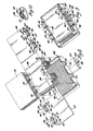
- Figure 1 is a perspective view of a cell element having aligned, abutting U-shaped, plate-lug collars in accordance with the present invention;
- Figure 2 is a section taken in the direction 2-2 of Figure 1;
- Figure 3 is a section taken in the direction 3-3 of Figure 1;
- Figure 4 illustrates one method of asembling a battery element having plate-lug collars in accordance with the present invention;
- Figure 5 is a perspective view of a battery container adapted to receive cell elements assembled as indicated in Figures 4 or 7;
- Figure 6 is a perspective view of a portion of the battery container of Figure 5 having cell elements made in accordance with the present invention inserted therein;
- Figure 7 illustrates another method of assembling a battery cell element having plate-lug collars in accordance with the present invention;
- Figure 8 is a perspective view of another method of assembling a battery cell having plate-lug collars in accordance with the present invention;
- Figure 9 is a perspective view of the battery cell after asembly according to the technique illustrated in Figure 8; and
- Figure 10 is a perspective view of a portion of a battery assembled in accordance with another embodiment of the present invention.
- Figure 1 depicts a battery cell element 1 comprising a stack of
positive plates 3 interleaved with a plurality of negative plates 5 and appropriate interplate separators (not shown). The plates comprise anactive material 7 supported on a conductive substrate, here shown as a gridwork of wires 9 joined at the top by a header 11. A plate lug 13 projects from eachpositive plate 3 and is aligned with other poistive plate lugs along one side (e.g., the top) of the cell element stack 1. The negative polarity plates 5 havesimilar plate lugs 15 thereon similarly aligned. A U-shaped insulating collar 17 is firmly secured to the root (i.e., adjacent the header 11) of each positive plate lug 13 and is aligned in abutting relation with similar collars on the aligned lugs 13.Similar collars 19 on thenegative lugs 15 are similarly aligned. While the following description is given in conjunction with the positive plates and their associated lugs and collars, it is to be understood that the substantial content thereof applies equally to the negative plates and associated lugs/collars. The collars space the aligned lugs from each other and preferably comprise a synthetic thermoplastics material (e.g., polypropylene or polyphenylene sulfide,) injection-moulded directly about the lugs. The collars 17 preferably have a U-shaped configuration including abase portion 21 engaging theroot 23 of each lug andupstanding legs 25 which flank thelateral edges 27 ofdistal portions 29 of the lugs which are more remote from theactive material 7 of the plate. The U-shaped collars 17, when aligned with similar collars, form atrough 31 for receiving an appropriate coupler, e.g., cast-in-place plate strap (not shown), for electrically joining thedistal portions 29 of the lugs together. In the case of a cast-in-place plate strap, thetrough 31 serves as a mould to shape the molten lead cast therein. End plates 33 are provided at the ends of eachtrough 31 opposite the end where the intercell connector is to be formed and serve to prevent molten lead from spilling out of the end of thetrough 31. - Each plate lug collar 17 and end plate 33 has an aperture 35 (i.e., about 1.65 mm (0.065 inch) diameter) formed therethrough to facilitate tying the several aligned lugs together in the stack. In this regard, when the collars 17 are aligned with one another, the
apertures 35 line up as best shown in Figures 2 and 3. A thread 37 (e.g., 1.60 mm (0.063 inch) diameter polypropylene) is inserted through theapertures 35 and has itsends - Figure 4 depicts another method of assembling a Pb-acid battery utilizing plate-lug collars in accordance with the present invention. According to this method, a plurality of
positive plates 43 are stacked together (i.e., interleaved with negative plates, not shown) to form onecell element stack 45. Similarly, a plurality of negative plates 47 are stacked together (i.e., unterleaved with positive plates, (not shown) to form anothercell element 49. The twocell elements intercell connector insert 51. Thelugs 53 of thepositive plates 43 ofstack 45 havepolypropylene collars 55 injection-moulded about the roots 57 thereof leaving the distal portions 59 thereof disposed above thecollars 55 for electrical coupling to each other by an appropriate means (e.g., plate strap). Similarly, a plurality of negative plates 47 have their lugs 61 provided withcollars 63 and are stacked together (i.e., interleaved with positive plates, not shown) to form thecell element stack 49. Thecell elements positive plate lugs 53 ofelement 45, the negative plate lugs 61 ofelement 49 and theintercell connector insert 51 are positioned as shown. Theintercell connector insert 51 comprises anintercell connector element 65 which bridges an intercell partition of the container andflanges 67 and 69 on the opposite ends of theelement 65. A steel mould 71 is then placed over the aligned lugs and insert. The mould 71 has afirst moulding cavity 73 encompassing the distal ends 75 of the negative plate lugs 61 and a second moulding cavity 77 encompassing the distal ends 59 of the positive plate lugs 53 at the same time. The aligned and abuttinglug collars mould cavities 73 and 77. Molten lead introduced into themould cavities 73, 77 melts and fuses to thedistal portions 75 and 59 of thelugs 61 and 53, respectively, as well as to the outer faces of theflanges 67 and 69 of theinsert 51. The molten lead essentially solidifies into plate straps 79 and 81 and joins the lugs and insert together in a unified assembly which is ready for insertion into an appropriate battery container 83 (see Figure 5). - The assembly formed as described in conjunction with Figure 4 is inserted into a battery container 83 which includes a plurality of
intercell partitions 85 for separating the cell compartments one from the other. Eachpartition 85 includes a slot 87 adapted to receive theintercell connector element 65 in the manner shown in Figure 6.Ribs 89 are provided on thepartition 85 adjacent the slot 87 and serve to engage the inside faces 91 of theflanges 67 and 69 of theintercell connector insert 51. The lower ends of theribs 89 engage a shelf 93 formed (i.e., in a second moulding operation) at the bottom of the slot 87 and together therewith define acavity 99. During assembly, thecell elements insert 51 engage theribs 89 and shelf 93 to enclose the sides of thecavity 99. Thereafter an injection-moulding mould (not shown) is positioned over thepartition 85 so as to encompass the slot 87 andflanges 67 and 69. Thermoplastics container material (e.g., polypropylene) is then injected into the mould so as: to fill thecavity 99; to seal theconnector element 65 in the slot and to envelop theperipheral edges 101 of theflanges 67 and 69; and to fill the remainder of the slot 87 above thecavity 99 to the top of thepartition 85. - Figure 7 depicts another similar method of assembling a battery utilizing the lug collars of the present invention.
Cell elements synthetic plastics collars intercell connector insert 115 in the same manner as described in conjunction with Figure 4. In this embodiment, however,U-shaped pieces 117 and 119 of lead-coated copper are positioned about thelugs 111 and 113. Thereafter a steel mould 121 is positioned about thepieces 117, 119 and insert 115. Molten lead is then introduced between thelegs 123 and 123ʹ of theU-shaped pieces 117 and 119 to join theinsert 115, plate lugs 111 and 113 andU-shaped pieces 117 and 119 together into a single unit 125. Thereafter the mould 121 is removed and thecell elements - Another application of plate-lug collars in accordance with the present invention involves forming the interplate and/or intercell connectors of the battery and/or terminals on the outside of the battery container such as, for example, as shown in Figures 8 and 9. A
battery cell element 126 is formed by interleaving a plurality ofnegative plates 127 with a plurality of positive plates 129 andintercell separators 131 essentially as described above. In the particular form shown, eachnegative plate 127 and positive plate 129 will have twolugs 133 and 135, respectively, for more efficient conduction of current to and from the plate. Individual insulatingcollars 137 are moulded about eachnegative plate lug 133. Similarly, individual insulatingcollars 139 are moulded about the positive plate lugs 135. Each of thecollars base portion 141,legs 143 and two sets A and B of flanges 145-145ʹ and 147-147ʹ which extend laterally outward from thelegs 143. The flange sets A and B definetherebetween openings discrete trays 153 which nest one within the other. Thetrays 153 each includeslots external walls 159 thereof for receiving thelug collars container wall 159 forming the edges of theslots openings collars legs 143 of the alignedcollars container tray 153 will be the end tray in a stack and hence will house the end cell of the battery. In such instances, a battery terminal 163 may be provided as follows. In this regard, several of the thelegs 143 are removed from acentre region 165 of the aligned collars. The ends of a Pb-coatedcopper strap 167 are fitted into theopenings 165 in the centre region and molten lead cast between thelegs 143 of the aligned collars to fuse the ends of thestrap 167 to the plate straps 161 at the time of their formation. Astud 169 projects from thestrap 167 for attachment to external circuitry. After the molten lead has solidified, the region about the connections is enclosed within a mould and hotsynthetic plastics material 170 injected thereabout to seal the collars within their respective slots and otherwise to put the connection in plastics material, as shown in phantom in Figure 9. - Figure 10 depicts a variation of the structure shown in Figure 8 wherein a lug collar 171 includes a single pair of oppositely-extending flanges 173 and 175 lying contiguous the container wall 177 and sealed thereto by plastics material 179 moulded thereabout.
Claims (12)
Applications Claiming Priority (2)
| Application Number | Priority Date | Filing Date | Title |
|---|---|---|---|
| US06/859,364 US4683180A (en) | 1986-05-05 | 1986-05-05 | Electric storage battery |
| US859364 | 1986-05-05 |
Publications (2)
| Publication Number | Publication Date |
|---|---|
| EP0244943A1 true EP0244943A1 (en) | 1987-11-11 |
| EP0244943B1 EP0244943B1 (en) | 1992-05-27 |
Family
ID=25330741
Family Applications (1)
| Application Number | Title | Priority Date | Filing Date |
|---|---|---|---|
| EP87302762A Expired - Lifetime EP0244943B1 (en) | 1986-05-05 | 1987-03-31 | Electric storage battery |
Country Status (5)
| Country | Link |
|---|---|
| US (1) | US4683180A (en) |
| EP (1) | EP0244943B1 (en) |
| JP (1) | JPS62268054A (en) |
| CA (1) | CA1279365C (en) |
| DE (1) | DE3779355D1 (en) |
Cited By (4)
| Publication number | Priority date | Publication date | Assignee | Title |
|---|---|---|---|---|
| EP0545293A1 (en) * | 1991-12-04 | 1993-06-09 | Gnb Industrial Battery Company | Galvanic cells and batteries having a novel grid, strap and intercell weld arrangement |
| EP0639864A1 (en) * | 1993-08-13 | 1995-02-22 | VARTA Batterie Aktiengesellschaft | Electric storage battery |
| FR2752090A1 (en) * | 1996-08-01 | 1998-02-06 | Accumulateurs Fixes | Electrochemical generator with top of electrode plates separated by polymer stringer |
| CN106663752A (en) * | 2014-06-02 | 2017-05-10 | 东宾制造有限公司 | Lead acid battery with molded well |
Families Citing this family (25)
| Publication number | Priority date | Publication date | Assignee | Title |
|---|---|---|---|---|
| US4742611A (en) * | 1987-06-29 | 1988-05-10 | General Motors Corporation | Battery assembly process and apparatus |
| US5198313A (en) * | 1989-06-14 | 1993-03-30 | Bolder Battery, Inc. | Battery end connector |
| US4983475A (en) * | 1990-02-13 | 1991-01-08 | Delans Darwin D | Bar for connecting together two plate straps of the same polarity on an electrochemical battery |
| US5227267A (en) * | 1990-11-01 | 1993-07-13 | Yardney Technical Products, Inc. | Disc electrode and busbar for an electrochemical battery |
| US5202198A (en) * | 1992-03-26 | 1993-04-13 | General Motors Corporation | Battery construction and method of connecting terminals to electrodes |
| USRE36102E (en) * | 1991-09-17 | 1999-02-16 | Globe-Union Inc. | Dual lug battery plate construction |
| US5227266A (en) * | 1991-12-04 | 1993-07-13 | Gnb Industrial Battery Company | Sealed lead-acid cell having a novel lug, and end cover assembly |
| US5308719A (en) * | 1992-09-21 | 1994-05-03 | Globe-Union Inc. | Lead acid batteries containing center lug plates and high performance cast-on straps |
| US5836371A (en) * | 1996-12-30 | 1998-11-17 | Gnb Technologies, Inc. | Method and apparatus for attaching terminal post straps to a battery plate group |
| US6274274B1 (en) | 1999-07-09 | 2001-08-14 | Johnson Controls Technology Company | Modification of the shape/surface finish of battery grid wires to improve paste adhesion |
| EP3035422B1 (en) | 2005-05-23 | 2019-02-20 | Johnson Controls Technology Company | Battery grid |
| RU2477549C2 (en) | 2007-03-02 | 2013-03-10 | Джонсон Кэнтрэулз Текнолэджи Кампэни | Accumulator negative grid manufacture method |
| KR20100017318A (en) * | 2007-04-24 | 2010-02-16 | 테믹 오토모티브 일렉트릭 모터스 게엠베하 | Energy storage assembly with poka-yoke connections |
| DE102008049852A1 (en) * | 2008-10-01 | 2010-04-08 | Behr Gmbh & Co. Kg | Device for the electrical connection of cell conductors |
| MX338843B (en) | 2010-03-03 | 2016-05-03 | Johnson Controls Tech Co | Battery grids and methods for manufacturing same. |
| CN101800300B (en) * | 2010-03-19 | 2012-06-06 | 浙江海悦自动化机械设备有限公司 | Automatic lug shaping mold |
| KR101831423B1 (en) | 2010-04-14 | 2018-02-22 | 존슨 컨트롤스 테크놀러지 컴퍼니 | Battery, battery plate assembly, and method of assembly |
| US9748578B2 (en) | 2010-04-14 | 2017-08-29 | Johnson Controls Technology Company | Battery and battery plate assembly |
| US9761883B2 (en) | 2011-11-03 | 2017-09-12 | Johnson Controls Technology Company | Battery grid with varied corrosion resistance |
| CN103316967B (en) * | 2013-06-21 | 2015-04-29 | 浙江海悦自动化机械股份有限公司 | Tab shaping mechanism |
| CN103433337B (en) * | 2013-09-10 | 2015-09-02 | 福建省建阳亚亨机械制造有限公司 | Accumulator pole group lug trimmer |
| DE202013012569U1 (en) | 2013-10-08 | 2017-07-17 | Johnson Controls Autobatterie Gmbh & Co. Kgaa | Grid arrangement for a plate-shaped battery electrode of an electrochemical accumulator and accumulator |
| DE102013111667A1 (en) | 2013-10-23 | 2015-04-23 | Johnson Controls Autobatterie Gmbh & Co. Kgaa | Grid arrangement for a plate-shaped battery electrode and accumulator |
| US12451493B2 (en) | 2017-01-27 | 2025-10-21 | Cps Technology Holdings Llc | Battery grid |
| JP7062603B2 (en) * | 2019-02-05 | 2022-05-06 | 本田技研工業株式会社 | Power storage device |
Citations (6)
| Publication number | Priority date | Publication date | Assignee | Title |
|---|---|---|---|---|
| US3753783A (en) * | 1971-11-24 | 1973-08-21 | Gen Battery Corp | Battery, components, and method of making |
| GB1379906A (en) * | 1971-06-09 | 1975-01-08 | Lucas Industries Ltd | Electric storage battery |
| FR2243510A1 (en) * | 1973-09-12 | 1975-04-04 | Chloride Batteries Au Ltd | |
| US3963521A (en) * | 1969-07-17 | 1976-06-15 | Accumulatorenfabrik Sonnenschein Gmbh | Leakproof bonding of storage battery components |
| US4022951A (en) * | 1973-09-20 | 1977-05-10 | Dunlop Australia Limited | Battery construction |
| FR2339257A1 (en) * | 1976-01-20 | 1977-08-19 | Hoppecke Zoellner Sohn Accu | LOW WEIGHT LEAD ACCUMULATOR |
Family Cites Families (5)
| Publication number | Priority date | Publication date | Assignee | Title |
|---|---|---|---|---|
| US2287802A (en) * | 1940-04-29 | 1942-06-30 | Willard Storage Battery Co | Manufacture of storage batteries |
| US2702829A (en) * | 1951-09-10 | 1955-02-22 | Miiton F Chapel | Storage battery cell plate integrator |
| GB969087A (en) * | 1962-06-12 | 1964-09-09 | ||
| FR1407690A (en) * | 1964-06-05 | 1965-08-06 | Baroclem Sa | Method of mounting the accumulator batteries and batteries thus produced |
| US3841915A (en) * | 1972-08-31 | 1974-10-15 | Gen Battery Corp | Battery, components, and method of making |
-
1986
- 1986-05-05 US US06/859,364 patent/US4683180A/en not_active Expired - Fee Related
-
1987
- 1987-01-29 CA CA000528483A patent/CA1279365C/en not_active Expired - Lifetime
- 1987-03-31 DE DE8787302762T patent/DE3779355D1/en not_active Expired - Lifetime
- 1987-03-31 EP EP87302762A patent/EP0244943B1/en not_active Expired - Lifetime
- 1987-05-01 JP JP62106461A patent/JPS62268054A/en active Pending
Patent Citations (6)
| Publication number | Priority date | Publication date | Assignee | Title |
|---|---|---|---|---|
| US3963521A (en) * | 1969-07-17 | 1976-06-15 | Accumulatorenfabrik Sonnenschein Gmbh | Leakproof bonding of storage battery components |
| GB1379906A (en) * | 1971-06-09 | 1975-01-08 | Lucas Industries Ltd | Electric storage battery |
| US3753783A (en) * | 1971-11-24 | 1973-08-21 | Gen Battery Corp | Battery, components, and method of making |
| FR2243510A1 (en) * | 1973-09-12 | 1975-04-04 | Chloride Batteries Au Ltd | |
| US4022951A (en) * | 1973-09-20 | 1977-05-10 | Dunlop Australia Limited | Battery construction |
| FR2339257A1 (en) * | 1976-01-20 | 1977-08-19 | Hoppecke Zoellner Sohn Accu | LOW WEIGHT LEAD ACCUMULATOR |
Cited By (5)
| Publication number | Priority date | Publication date | Assignee | Title |
|---|---|---|---|---|
| EP0545293A1 (en) * | 1991-12-04 | 1993-06-09 | Gnb Industrial Battery Company | Galvanic cells and batteries having a novel grid, strap and intercell weld arrangement |
| EP0639864A1 (en) * | 1993-08-13 | 1995-02-22 | VARTA Batterie Aktiengesellschaft | Electric storage battery |
| FR2752090A1 (en) * | 1996-08-01 | 1998-02-06 | Accumulateurs Fixes | Electrochemical generator with top of electrode plates separated by polymer stringer |
| CN106663752A (en) * | 2014-06-02 | 2017-05-10 | 东宾制造有限公司 | Lead acid battery with molded well |
| CN106663752B (en) * | 2014-06-02 | 2019-05-10 | 东宾制造有限公司 | Lead acid battery with molded well |
Also Published As
| Publication number | Publication date |
|---|---|
| US4683180A (en) | 1987-07-28 |
| DE3779355D1 (en) | 1992-07-02 |
| EP0244943B1 (en) | 1992-05-27 |
| CA1279365C (en) | 1991-01-22 |
| JPS62268054A (en) | 1987-11-20 |
Similar Documents
| Publication | Publication Date | Title |
|---|---|---|
| EP0244943B1 (en) | Electric storage battery | |
| US4800142A (en) | Electric storage battery | |
| US5256502A (en) | Modular, multicell lead-acid batteries | |
| US6939642B2 (en) | Prismatic battery module and method for manufacturing the same | |
| EP0589549B1 (en) | Lead acid batteries containing center lug plates and high performance cast-on straps | |
| US5512065A (en) | Methods for assembling lead-acid batteries | |
| EP0314318B1 (en) | Multicell recombinant lead-acid battery with vibration resistant intercell connector | |
| US4022951A (en) | Battery construction | |
| CN109155380B (en) | Battery module including cover assembly | |
| EP2612391B1 (en) | Low aspect ratio spiral-wound vrla battery | |
| US3988169A (en) | Method of molding connectors in electrical accumulators | |
| CN106663752B (en) | Lead acid battery with molded well | |
| EP0065348B1 (en) | Battery intercell connector manifold | |
| CA1046138A (en) | Rechargeable battery having a plurality of frames supporting active material and separators | |
| US4675991A (en) | Method of assembling electric storage batteries | |
| JP2025134067A (en) | Energy storage devices | |
| US4764182A (en) | Electric storage battery | |
| US3753783A (en) | Battery, components, and method of making | |
| US4423123A (en) | Electric storage battery and a method of making the same | |
| US3514342A (en) | Method of making a battery | |
| US5731103A (en) | Method and apparatus for positioning a battery terminal strap | |
| EP0217550A1 (en) | Galvanic cell | |
| KR100709884B1 (en) | Square secondary battery | |
| JPH0515031B2 (en) | ||
| EP0251970A1 (en) | An electric storage battery |
Legal Events
| Date | Code | Title | Description |
|---|---|---|---|
| PUAI | Public reference made under article 153(3) epc to a published international application that has entered the european phase |
Free format text: ORIGINAL CODE: 0009012 |
|
| AK | Designated contracting states |
Kind code of ref document: A1 Designated state(s): DE FR GB IT |
|
| 17P | Request for examination filed |
Effective date: 19880215 |
|
| 17Q | First examination report despatched |
Effective date: 19890614 |
|
| GRAA | (expected) grant |
Free format text: ORIGINAL CODE: 0009210 |
|
| ITF | It: translation for a ep patent filed | ||
| AK | Designated contracting states |
Kind code of ref document: B1 Designated state(s): DE FR GB IT |
|
| PG25 | Lapsed in a contracting state [announced via postgrant information from national office to epo] |
Ref country code: FR Effective date: 19920527 |
|
| REF | Corresponds to: |
Ref document number: 3779355 Country of ref document: DE Date of ref document: 19920702 |
|
| EN | Fr: translation not filed | ||
| PG25 | Lapsed in a contracting state [announced via postgrant information from national office to epo] |
Ref country code: GB Effective date: 19930331 |
|
| PLBE | No opposition filed within time limit |
Free format text: ORIGINAL CODE: 0009261 |
|
| STAA | Information on the status of an ep patent application or granted ep patent |
Free format text: STATUS: NO OPPOSITION FILED WITHIN TIME LIMIT |
|
| 26N | No opposition filed | ||
| GBPC | Gb: european patent ceased through non-payment of renewal fee |
Effective date: 19930331 |
|
| PG25 | Lapsed in a contracting state [announced via postgrant information from national office to epo] |
Ref country code: DE Effective date: 19931201 |
|
| PG25 | Lapsed in a contracting state [announced via postgrant information from national office to epo] |
Ref country code: IT Free format text: LAPSE BECAUSE OF NON-PAYMENT OF DUE FEES;WARNING: LAPSES OF ITALIAN PATENTS WITH EFFECTIVE DATE BEFORE 2007 MAY HAVE OCCURRED AT ANY TIME BEFORE 2007. THE CORRECT EFFECTIVE DATE MAY BE DIFFERENT FROM THE ONE RECORDED. Effective date: 20050331 |