EP0244092A1 - Optical apparatus and method for examining an object - Google Patents
Optical apparatus and method for examining an object Download PDFInfo
- Publication number
- EP0244092A1 EP0244092A1 EP87302776A EP87302776A EP0244092A1 EP 0244092 A1 EP0244092 A1 EP 0244092A1 EP 87302776 A EP87302776 A EP 87302776A EP 87302776 A EP87302776 A EP 87302776A EP 0244092 A1 EP0244092 A1 EP 0244092A1
- Authority
- EP
- European Patent Office
- Prior art keywords
- radiation
- refracted
- predetermined angular
- angular limits
- reflected
- Prior art date
- Legal status (The legal status is an assumption and is not a legal conclusion. Google has not performed a legal analysis and makes no representation as to the accuracy of the status listed.)
- Granted
Links
- 230000003287 optical effect Effects 0.000 title description 9
- 238000000034 method Methods 0.000 title description 4
- 230000005855 radiation Effects 0.000 claims abstract description 46
- 244000182067 Fraxinus ornus Species 0.000 claims 1
- 230000000063 preceeding effect Effects 0.000 claims 1
- 239000000463 material Substances 0.000 description 8
- 229920005439 Perspex® Polymers 0.000 description 2
- 238000004519 manufacturing process Methods 0.000 description 2
- 239000004926 polymethyl methacrylate Substances 0.000 description 2
- 230000001154 acute effect Effects 0.000 description 1
- 230000001427 coherent effect Effects 0.000 description 1
- 230000000052 comparative effect Effects 0.000 description 1
- 230000001419 dependent effect Effects 0.000 description 1
- 238000007689 inspection Methods 0.000 description 1
- 238000009304 pastoral farming Methods 0.000 description 1
- 239000004753 textile Substances 0.000 description 1
Images

Classifications
-
- G—PHYSICS
- G01—MEASURING; TESTING
- G01N—INVESTIGATING OR ANALYSING MATERIALS BY DETERMINING THEIR CHEMICAL OR PHYSICAL PROPERTIES
- G01N21/00—Investigating or analysing materials by the use of optical means, i.e. using sub-millimetre waves, infrared, visible or ultraviolet light
- G01N21/84—Systems specially adapted for particular applications
- G01N21/88—Investigating the presence of flaws or contamination
- G01N21/89—Investigating the presence of flaws or contamination in moving material, e.g. running paper or textiles
- G01N21/8901—Optical details; Scanning details
-
- G—PHYSICS
- G01—MEASURING; TESTING
- G01J—MEASUREMENT OF INTENSITY, VELOCITY, SPECTRAL CONTENT, POLARISATION, PHASE OR PULSE CHARACTERISTICS OF INFRARED, VISIBLE OR ULTRAVIOLET LIGHT; COLORIMETRY; RADIATION PYROMETRY
- G01J1/00—Photometry, e.g. photographic exposure meter
- G01J1/02—Details
- G01J1/04—Optical or mechanical part supplementary adjustable parts
- G01J1/0407—Optical elements not provided otherwise, e.g. manifolds, windows, holograms, gratings
- G01J1/0477—Prisms, wedges
-
- G—PHYSICS
- G01—MEASURING; TESTING
- G01J—MEASUREMENT OF INTENSITY, VELOCITY, SPECTRAL CONTENT, POLARISATION, PHASE OR PULSE CHARACTERISTICS OF INFRARED, VISIBLE OR ULTRAVIOLET LIGHT; COLORIMETRY; RADIATION PYROMETRY
- G01J1/00—Photometry, e.g. photographic exposure meter
- G01J1/02—Details
- G01J1/04—Optical or mechanical part supplementary adjustable parts
- G01J1/06—Restricting the angle of incident light
-
- G—PHYSICS
- G01—MEASURING; TESTING
- G01N—INVESTIGATING OR ANALYSING MATERIALS BY DETERMINING THEIR CHEMICAL OR PHYSICAL PROPERTIES
- G01N21/00—Investigating or analysing materials by the use of optical means, i.e. using sub-millimetre waves, infrared, visible or ultraviolet light
- G01N21/17—Systems in which incident light is modified in accordance with the properties of the material investigated
- G01N21/47—Scattering, i.e. diffuse reflection
- G01N21/4738—Diffuse reflection, e.g. also for testing fluids, fibrous materials
Definitions
- the present invention relates to an optical apparatus and method for examining an object.
- Many methods for examining objects optically have been proposed and they frequently comprise means for scanning radiation across the object under examination and collecting the radiation influenced by the object to determine features including faults or flaws in the object.
- a particular problem which arises in examining some objects having a generally flat surface is to detect, by optical inspection apparatus, discontinuities in the surface such as creases or abrupt changes in surface level.
- Such edges which are caused by abrupt changes of surface level also occur in other situations where an object is to be examined and in some circumstances it is desirable to be able to obtain some indication of the extent of change of the surface level. For example, a certain degree of tolerance of change of surface level may be permissable when dealing with, for example, pits or craters in a surface.
- the present invention provides according to one aspect an optical apparatus for receiving radiation within defined angular limits, the optical apparatus including optical means through which the radiation is passed and in which the radiation is internally reflected, and the opposite angular limits of the receipt of radiation are defined by total internal reflection.
- the apparatus also provides an optical apparatus as claimed in claim 1 of our patent 2117897 in which the radiation collection means includes means for defining said one or more predetermined directions by means of total internal reflection.
- the object to be examined comprises a diffuse surface which may be, by way of example only, a sheet of material 10 the width of which is illustrated in Figure 1 between points 11 and 12 and which moves in a direction shown by the arrow 13 in Figure 2.
- the sheet of material may comprise paper, textile or the like.
- the sheet 10 is scanned by a focussed beam of light 14 which is scanned from edge 11 to edge 12 in the direction of the arrow 16.
- the beam of light may be provided by a laser beam 17.
- the incident beam 17 is reflected by the sheet 10 in a generally diffuse nature as is described with respect to Figures 1 and 2 of our earlier patent 2117897.
- Figure 3 shows the surface of the sheet 10 which has an edge or discontinuity 10C caused by a change from a first surface portion 10A to a second surface portion 10B.
- the discontinuity 10C may be in the form of a crease or other discontinuity.
- a beam of radiation in the form of the incident laser beam 17 strikes the surface of the sheet 10 and scatters radiation as is indicated by the short arrows 18.
- a further use of comparison of the light received by the light receiving means 19 and 21 is in providing an indication of the height difference between the surface portion 10A and 10B.
- the linear distance between laser beam position X and Y is dependent upon the height difference (H) between surface parts 10A and 10B.
- H height difference
- a small step that is a samll height H between the surface parts 10A and 10B can be tolerated but a larger step cannot be tolerated.
- Apparatus of this type therefore, provides a means for discriminating between acceptable and unacceptable surface irregularities.
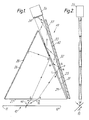
- the light receiving means 19 will now be described with reference to Figures 1 and 2.
- the light receiving means 19 comprises a first perspex prism 26 the base 27 of which extends parallel to and above the sheet 10 and extends beyond the edges 11 and 12.
- a side face 28 of the prism 26 has a matt black surface to absorb light incident on the face 28 from within the prism.
- the upper face 29 of the prism 26 extends as shown in Figure 1.
- the upper face 29 of the prism 26 spaced from a coplanar lower face 31 of a second perspex prism 32 by an air gap 25, the second prism 32 having a second upper face 33 which extends from an apex adjacent the apex between the base 27 and upper face 29 of the first prism 26.
- a third, end face 34 of the second prism is mounted adjacent a photomultiplier 36.
- a plane mirror 37 is mounted adjacent to and parallel to the upper face 33 there being provided a small air gap 40 between the upper face 33 and the mirror 37.
- Figure 1 shows the limiting rays receivable by the light collection means 19 which correspond to angles B and C in Figure 5.
- the ray from the diffusing surface is refracted at G on the base surface 27 of the first prism 26, and is totally internally reflected at H on the upper face 29 to be reflected back along line HJ to J on the side face 28 where it is absorbed by the matt black surface.
- the other limiting ray FKLMNPQR is refracted at K on the base face 27 of the first prism 26, refracted at L on the upper face 29 and passes across the air gap 25 into the second prism 32 at M, is refracted through the upper face 33 of the second prism 32 at N, is reflected at P by the plane miror 37, re-enters the second prism at Q, and is refracted at R on the lower face 31 of the second prism. It passes into the air gap 25 at a grazing angle at so will not re-enter the prism 26 and is lost to the system.
- the air gap 25 may be eliminated.
- the photomultiplier 36 may be replaced by a light source which may be a non-coherent light source which will thereby produce light which strikes the surface 11 within the angles defined, in Figure 1 by the rays FG and FK. The complete length of the surface 11 will be illuminated but with light from this particular angular direction.
- a light source which may be a non-coherent light source which will thereby produce light which strikes the surface 11 within the angles defined, in Figure 1 by the rays FG and FK. The complete length of the surface 11 will be illuminated but with light from this particular angular direction.
Abstract
Description
- The present invention relates to an optical apparatus and method for examining an object. Many methods for examining objects optically have been proposed and they frequently comprise means for scanning radiation across the object under examination and collecting the radiation influenced by the object to determine features including faults or flaws in the object.
- A particular problem which arises in examining some objects having a generally flat surface (such as sheet material) is to detect, by optical inspection apparatus, discontinuities in the surface such as creases or abrupt changes in surface level.
- Two examples may be given but there are many others. In the manufacture of sheet material creases can occur in the material which provide an abrupt change of the surface of the material. Secondly, in the production of newspapers, before printing, a mock-up of the newspaper is produced which comprises a sheet of paper the size of the finished product and glued to this paper are a number of other pieces of paper carrying some of the various articles which are to appear on the page. The reason they are produced separately is that they can be moved around to change the layout during the planning of that page of the newspaper. A problem arises in printing the newspaper from this mock-up in that where the separate pieces of paper appear stuck on to the large sheet of paper there are provided discontinuities in the form of edges. This problem is particularly acute in a case where the image of that page is to be transmitted to a remote location in the form of a linear digital (or analogue) signal which is produced by scanning across the page and detecting, during the scan, the light signal reflected or otherwise influenced by the surface of the paper. Clearly one wishes to pass signals which correspond to the blank paper and to the print since that will reproduce the image but it is possible with this system that the shadows caused by edges between the sheets of paper which have been stuck on to the large sheet of paper will also be reproduced and this is clearly undesirable.
- Such edges which are caused by abrupt changes of surface level also occur in other situations where an object is to be examined and in some circumstances it is desirable to be able to obtain some indication of the extent of change of the surface level. For example, a certain degree of tolerance of change of surface level may be permissable when dealing with, for example, pits or craters in a surface.
- An earlier arrangement is described in our British Patent Specification 2117897. In this, radiation is reflected from a radiation diffusing surface is collected from a predetermined direction other than normal to the surface by a variety of means which one can summarise as being of a "Venetian blind" type.
- The present invention provides according to one aspect an optical apparatus for receiving radiation within defined angular limits, the optical apparatus including optical means through which the radiation is passed and in which the radiation is internally reflected, and the opposite angular limits of the receipt of radiation are defined by total internal reflection.
- The apparatus also provides an optical apparatus as claimed in claim 1 of our patent 2117897 in which the radiation collection means includes means for defining said one or more predetermined directions by means of total internal reflection.
- Throughout the specification we shall refer to "light" and "optical". The normal arrangement uses visible light, but it is possible to operate the invention with radiation of other wavelengths such as infra red or ultra violet and the words light and optical should be interpreted accordingly.
- Preferred embodiments of the invention will now be described by way of example only and with reference to the accompanying drawings in which:
- Figure 1 is a front view of a light collection apparatus according to a first aspect of the invention,
- Figure 2 is a side view of the apparatus of Figure 1,
- Figure 3 is a enlarged section of part of a surfafce to be examined showing the method of operation of the invention.
- Referring to Figure 1 the object to be examined comprises a diffuse surface which may be, by way of example only, a sheet of
material 10 the width of which is illustrated in Figure 1 betweenpoints arrow 13 in Figure 2. The sheet of material may comprise paper, textile or the like. Thesheet 10 is scanned by a focussed beam oflight 14 which is scanned fromedge 11 toedge 12 in the direction of thearrow 16. The beam of light may be provided by alaser beam 17. Theincident beam 17 is reflected by thesheet 10 in a generally diffuse nature as is described with respect to Figures 1 and 2 of our earlier patent 2117897. - Figure 3 shows the surface of the
sheet 10 which has an edge ordiscontinuity 10C caused by a change from afirst surface portion 10A to asecond surface portion 10B. Thediscontinuity 10C may be in the form of a crease or other discontinuity. As is described in our earlier patent 2117897 a beam of radiation in the form of theincident laser beam 17, strikes the surface of thesheet 10 and scatters radiation as is indicated by theshort arrows 18. - There is provided
means 19 for receiving the scattered radiation from the surface within a wedge of angles indicated by A in Figure 5 between angular limits B and C with respect to surface of thesheet 10. Whilst thelaser beam 17 is to the left of the position illustrated as X in figure 5 then scatttered radiation indicated by thesmall arrows 18 can be received by thelight receiving means 19. However, whilst thelaser beam 17 between the positions X and Y illustrated typically by position Z the light receiving means 19 cannot receive scattered radiation from the surface of thesheet 10 because of theedge 10C between thesurfaces light receiving means 19 and therefore there is no output fromlight receiving means 19. - As is explained in our earlier patent 2117897 if there is provided a second light receiving means 21 which similarly receives radiation only between anglular limits D and E then a comparison of the light received by
means 19 and 21 will indicate whether the scattered light has been reflected from a normal part of the surface of sheet 10 (in which case comparative values of the light received bymeans 19 and 21 will be the same, although the absolute values of light received may vary if, for example, the sheet carries printed material) or there is a crease or discontinuity as shown in Figure 3 in which case the light received by 19 and 21 will be different. In this case the light received by 21 if thelaser beam 17 is between X and Y will be greater than that received bymeans 19. - The use of a comparison between the light received by
light receiving means 19 and 21 has been utilised in our earlier 2117897 to eliminate the shadows cast by smaller sheets pasted onto a larger sheet in a mock-up of a page of a newspaper. - A further use of comparison of the light received by the
light receiving means 19 and 21 is in providing an indication of the height difference between thesurface portion surface parts surface parts - The light receiving means 19 will now be described with reference to Figures 1 and 2. The light receiving means 19 comprises a
first perspex prism 26 thebase 27 of which extends parallel to and above thesheet 10 and extends beyond theedges side face 28 of theprism 26 has a matt black surface to absorb light incident on theface 28 from within the prism. Theupper face 29 of theprism 26 extends as shown in Figure 1. - The
upper face 29 of theprism 26 spaced from a coplanarlower face 31 of asecond perspex prism 32 by anair gap 25, thesecond prism 32 having a secondupper face 33 which extends from an apex adjacent the apex between thebase 27 andupper face 29 of thefirst prism 26. A third,end face 34 of the second prism is mounted adjacent aphotomultiplier 36. Aplane mirror 37 is mounted adjacent to and parallel to theupper face 33 there being provided asmall air gap 40 between theupper face 33 and themirror 37. Figure 1 shows the limiting rays receivable by the light collection means 19 which correspond to angles B and C in Figure 5. - Considering the left hand limiting ray, FGHJ, the ray from the diffusing surface is refracted at G on the
base surface 27 of thefirst prism 26, and is totally internally reflected at H on theupper face 29 to be reflected back along line HJ to J on theside face 28 where it is absorbed by the matt black surface. - The other limiting ray FKLMNPQR is refracted at K on the
base face 27 of thefirst prism 26, refracted at L on theupper face 29 and passes across theair gap 25 into thesecond prism 32 at M, is refracted through theupper face 33 of thesecond prism 32 at N, is reflected at P by theplane miror 37, re-enters the second prism at Q, and is refracted at R on thelower face 31 of the second prism. It passes into theair gap 25 at a grazing angle at so will not re-enter theprism 26 and is lost to the system. - Rays between these two limiting rays enter the
base face 27, are refracted through theupper face 29 of thefirst prism 26, cross theair gap 25 and enter thelower face 31 of thesecond prism 32, and are successively totally internally reflected at theupper face 33 andlower face 31 of the second prism so as to pass up through thesecond prism 32 to theend face 34 where they enter thephotomultiplier 36. - The invention is not restricted to the details of the foregoing example.
- If the two prisms are of materials of different refractive indices then the
air gap 25 may be eliminated. - As will be understood the two
light receiving means 19 and 21 of Figure 3 may be similar. - In an alternative arrangement, for a different purposes, the
photomultiplier 36 may be replaced by a light source which may be a non-coherent light source which will thereby produce light which strikes thesurface 11 within the angles defined, in Figure 1 by the rays FG and FK. The complete length of thesurface 11 will be illuminated but with light from this particular angular direction.
Claims (8)
Applications Claiming Priority (2)
| Application Number | Priority Date | Filing Date | Title |
|---|---|---|---|
| GB8610304 | 1986-04-28 | ||
| GB868610304A GB8610304D0 (en) | 1986-04-28 | 1986-04-28 | Optical apparatus |
Publications (2)
| Publication Number | Publication Date |
|---|---|
| EP0244092A1 true EP0244092A1 (en) | 1987-11-04 |
| EP0244092B1 EP0244092B1 (en) | 1991-04-17 |
Family
ID=10596951
Family Applications (1)
| Application Number | Title | Priority Date | Filing Date |
|---|---|---|---|
| EP87302776A Expired EP0244092B1 (en) | 1986-04-28 | 1987-03-31 | Optical apparatus and method for examining an object |
Country Status (5)
| Country | Link |
|---|---|
| US (1) | US4851696A (en) |
| EP (1) | EP0244092B1 (en) |
| CA (1) | CA1271822A (en) |
| DE (1) | DE3769360D1 (en) |
| GB (1) | GB8610304D0 (en) |
Cited By (2)
| Publication number | Priority date | Publication date | Assignee | Title |
|---|---|---|---|---|
| EP1092965A1 (en) * | 1999-10-14 | 2001-04-18 | Elop Electro-Optics Industries Ltd. | Numerical aperture limiter |
| WO2002010698A1 (en) * | 2000-07-28 | 2002-02-07 | Otsuka Electronics Co., Ltd. | Light spectrum detecting apparatus |
Families Citing this family (8)
| Publication number | Priority date | Publication date | Assignee | Title |
|---|---|---|---|---|
| US4943732A (en) * | 1989-08-16 | 1990-07-24 | Micrion Corporation | Method and apparatus for defect detection and location |
| US5852287A (en) * | 1993-08-17 | 1998-12-22 | Sony Corporation | Semiconductor optical device for code reader |
| SE502547C2 (en) * | 1994-03-21 | 1995-11-13 | Tetra Laval Holdings & Finance | Method and apparatus for sensing the position of a transverse pig in a packaging web |
| US5949550A (en) * | 1997-08-21 | 1999-09-07 | Consolidated Papers, Inc. | Method and apparatus for detecting defects in a moving web |
| US20040159804A1 (en) * | 2003-02-13 | 2004-08-19 | Boutet John C. | Prism use for CR collector efficiency boost |
| DE102010026443B4 (en) * | 2010-07-08 | 2016-08-04 | Precitec Kg | Device for measuring the power of a laser beam and laser processing head with such a device |
| US9027477B2 (en) | 2013-03-28 | 2015-05-12 | Xerox Corporation | Wrinkle detection in continuous feed printers |
| JP6974252B2 (en) * | 2018-05-15 | 2021-12-01 | 京セラ株式会社 | Electromagnetic wave detection device and information acquisition system |
Citations (4)
| Publication number | Priority date | Publication date | Assignee | Title |
|---|---|---|---|---|
| GB472448A (en) * | 1936-03-11 | 1937-09-23 | Zeiss Ikon Ag | Improvements in or relating to photoelectric exposure meters |
| GB1044950A (en) * | 1962-11-20 | 1966-10-05 | English Electric Leo Marconi C | Improvements in or relating to optical elements for photo-electric sensing devices |
| US4378159A (en) * | 1981-03-30 | 1983-03-29 | Tencor Instruments | Scanning contaminant and defect detector |
| GB2117897A (en) * | 1982-03-03 | 1983-10-19 | Sira Ltd | Detecting surface defects |
Family Cites Families (2)
| Publication number | Priority date | Publication date | Assignee | Title |
|---|---|---|---|---|
| DE2433683C3 (en) * | 1974-07-12 | 1979-02-22 | Erwin Sick Gmbh Optik-Elektronik, 7808 Waldkirch | Device for monitoring a material web for defects |
| US4601576A (en) * | 1983-12-09 | 1986-07-22 | Tencor Instruments | Light collector for optical contaminant and flaw detector |
-
1986
- 1986-04-28 GB GB868610304A patent/GB8610304D0/en active Pending
-
1987
- 1987-03-31 DE DE8787302776T patent/DE3769360D1/en not_active Expired - Fee Related
- 1987-03-31 EP EP87302776A patent/EP0244092B1/en not_active Expired
- 1987-04-15 US US07/042,227 patent/US4851696A/en not_active Expired - Fee Related
- 1987-04-28 CA CA000535821A patent/CA1271822A/en not_active Expired - Fee Related
Patent Citations (4)
| Publication number | Priority date | Publication date | Assignee | Title |
|---|---|---|---|---|
| GB472448A (en) * | 1936-03-11 | 1937-09-23 | Zeiss Ikon Ag | Improvements in or relating to photoelectric exposure meters |
| GB1044950A (en) * | 1962-11-20 | 1966-10-05 | English Electric Leo Marconi C | Improvements in or relating to optical elements for photo-electric sensing devices |
| US4378159A (en) * | 1981-03-30 | 1983-03-29 | Tencor Instruments | Scanning contaminant and defect detector |
| GB2117897A (en) * | 1982-03-03 | 1983-10-19 | Sira Ltd | Detecting surface defects |
Cited By (5)
| Publication number | Priority date | Publication date | Assignee | Title |
|---|---|---|---|---|
| EP1092965A1 (en) * | 1999-10-14 | 2001-04-18 | Elop Electro-Optics Industries Ltd. | Numerical aperture limiter |
| SG87186A1 (en) * | 1999-10-14 | 2002-03-19 | Elop Electrooptics Ind Ltd | Numerical aperture limiter |
| US6624956B1 (en) | 1999-10-14 | 2003-09-23 | Elop Electro-Optics Industries | Numerical aperture limiter |
| WO2002010698A1 (en) * | 2000-07-28 | 2002-02-07 | Otsuka Electronics Co., Ltd. | Light spectrum detecting apparatus |
| US6859274B2 (en) | 2000-07-28 | 2005-02-22 | Otsuka Electronics Co., Ltd. | Light spectrum detecting apparatus |
Also Published As
| Publication number | Publication date |
|---|---|
| CA1271822A (en) | 1990-07-17 |
| GB8610304D0 (en) | 1986-06-04 |
| US4851696A (en) | 1989-07-25 |
| DE3769360D1 (en) | 1991-05-23 |
| EP0244092B1 (en) | 1991-04-17 |
Similar Documents
| Publication | Publication Date | Title |
|---|---|---|
| JP2795595B2 (en) | Defect detection method for transparent plate | |
| US4260899A (en) | Wide web laser scanner flaw detection method and apparatus | |
| US4223346A (en) | Automatic defect detecting inspection apparatus | |
| US4483615A (en) | Method and apparatus for detecting checks in glass tubes | |
| JPH08278257A (en) | Moving-object inspecting method | |
| EP1777511A3 (en) | Scanning system for inspecting anomalies on surfaces | |
| JPH03267745A (en) | Surface property detecting method | |
| US4737650A (en) | Inspection apparatus | |
| EP0244092B1 (en) | Optical apparatus and method for examining an object | |
| JPH01143945A (en) | Detecting method for defect in tape | |
| US4861164A (en) | Apparatus for separating specular from diffuse radiation | |
| ES8500445A1 (en) | Optical detection of radial reflective defects | |
| US3814943A (en) | Method of and apparatus for analysing patterns and inspecting objects | |
| JPH0760262B2 (en) | Reticle inspection method and device | |
| GB2044921A (en) | Optical apparatus for inspecting defects | |
| US6346713B1 (en) | Method and installation for inspecting an article for defects | |
| GB2117897A (en) | Detecting surface defects | |
| JPS6129453B2 (en) | ||
| US4038554A (en) | Detection of flaws in a moving web of transparent material | |
| JPH0833354B2 (en) | Defect inspection equipment | |
| EP0408337A1 (en) | Sheet inspection method and apparatus | |
| JPS61176838A (en) | Inspection of defect of transparent or semi-transparent plate-shaped body | |
| JPH0511574B2 (en) | ||
| GB2054835A (en) | Scanning Apparatus for Flaw Detection | |
| JPH0228815B2 (en) |
Legal Events
| Date | Code | Title | Description |
|---|---|---|---|
| PUAI | Public reference made under article 153(3) epc to a published international application that has entered the european phase |
Free format text: ORIGINAL CODE: 0009012 |
|
| AK | Designated contracting states |
Kind code of ref document: A1 Designated state(s): DE FR GB IT SE |
|
| 17P | Request for examination filed |
Effective date: 19880220 |
|
| 17Q | First examination report despatched |
Effective date: 19900510 |
|
| GRAA | (expected) grant |
Free format text: ORIGINAL CODE: 0009210 |
|
| AK | Designated contracting states |
Kind code of ref document: B1 Designated state(s): DE FR GB IT SE |
|
| PG25 | Lapsed in a contracting state [announced via postgrant information from national office to epo] |
Ref country code: IT Free format text: LAPSE BECAUSE OF FAILURE TO SUBMIT A TRANSLATION OF THE DESCRIPTION OR TO PAY THE FEE WITHIN THE PRE;WARNING: LAPSES OF ITALIAN PATENTS WITH EFFECTIVE DATE BEFORE 2007 MAY HAVE OCCURRED AT ANY TIME BEFORE 2007. THE CORRECT EFFECTIVE DATE MAY BE DIFFERENT FROM THE ONE RECORDED.SCRIBED TIME-LIMIT Effective date: 19910417 Ref country code: SE Effective date: 19910417 |
|
| ET | Fr: translation filed | ||
| REF | Corresponds to: |
Ref document number: 3769360 Country of ref document: DE Date of ref document: 19910523 |
|
| PLBE | No opposition filed within time limit |
Free format text: ORIGINAL CODE: 0009261 |
|
| STAA | Information on the status of an ep patent application or granted ep patent |
Free format text: STATUS: NO OPPOSITION FILED WITHIN TIME LIMIT |
|
| 26N | No opposition filed | ||
| PGFP | Annual fee paid to national office [announced via postgrant information from national office to epo] |
Ref country code: GB Payment date: 19960105 Year of fee payment: 10 |
|
| PGFP | Annual fee paid to national office [announced via postgrant information from national office to epo] |
Ref country code: FR Payment date: 19960130 Year of fee payment: 10 |
|
| PGFP | Annual fee paid to national office [announced via postgrant information from national office to epo] |
Ref country code: DE Payment date: 19960525 Year of fee payment: 10 |
|
| PG25 | Lapsed in a contracting state [announced via postgrant information from national office to epo] |
Ref country code: GB Effective date: 19970331 |
|
| GBPC | Gb: european patent ceased through non-payment of renewal fee |
Effective date: 19970331 |
|
| PG25 | Lapsed in a contracting state [announced via postgrant information from national office to epo] |
Ref country code: FR Free format text: LAPSE BECAUSE OF NON-PAYMENT OF DUE FEES Effective date: 19971128 |
|
| PG25 | Lapsed in a contracting state [announced via postgrant information from national office to epo] |
Ref country code: DE Effective date: 19971202 |
|
| REG | Reference to a national code |
Ref country code: FR Ref legal event code: ST |