EP0243851A1 - Method and apparatus for making reinforcements for pneumatic tyres - Google Patents
Method and apparatus for making reinforcements for pneumatic tyres Download PDFInfo
- Publication number
- EP0243851A1 EP0243851A1 EP87105841A EP87105841A EP0243851A1 EP 0243851 A1 EP0243851 A1 EP 0243851A1 EP 87105841 A EP87105841 A EP 87105841A EP 87105841 A EP87105841 A EP 87105841A EP 0243851 A1 EP0243851 A1 EP 0243851A1
- Authority
- EP
- European Patent Office
- Prior art keywords
- wire
- retaining means
- rod
- axially
- reinforcement
- Prior art date
- Legal status (The legal status is an assumption and is not a legal conclusion. Google has not performed a legal analysis and makes no representation as to the accuracy of the status listed.)
- Granted
Links
Images


Classifications
-
- B—PERFORMING OPERATIONS; TRANSPORTING
- B29—WORKING OF PLASTICS; WORKING OF SUBSTANCES IN A PLASTIC STATE IN GENERAL
- B29D—PRODUCING PARTICULAR ARTICLES FROM PLASTICS OR FROM SUBSTANCES IN A PLASTIC STATE
- B29D30/00—Producing pneumatic or solid tyres or parts thereof
- B29D30/06—Pneumatic tyres or parts thereof (e.g. produced by casting, moulding, compression moulding, injection moulding, centrifugal casting)
- B29D30/38—Textile inserts, e.g. cord or canvas layers, for tyres; Treatment of inserts prior to building the tyre
-
- B—PERFORMING OPERATIONS; TRANSPORTING
- B29—WORKING OF PLASTICS; WORKING OF SUBSTANCES IN A PLASTIC STATE IN GENERAL
- B29D—PRODUCING PARTICULAR ARTICLES FROM PLASTICS OR FROM SUBSTANCES IN A PLASTIC STATE
- B29D30/00—Producing pneumatic or solid tyres or parts thereof
- B29D30/06—Pneumatic tyres or parts thereof (e.g. produced by casting, moulding, compression moulding, injection moulding, centrifugal casting)
- B29D30/08—Building tyres
- B29D30/10—Building tyres on round cores, i.e. the shape of the core is approximately identical with the shape of the completed tyre
- B29D30/16—Applying the layers; Guiding or stretching the layers during application
- B29D30/1635—Applying the layers; Guiding or stretching the layers during application by feeding a continuous band and moving it back and forth (zig-zag) to form an annular element
-
- B—PERFORMING OPERATIONS; TRANSPORTING
- B29—WORKING OF PLASTICS; WORKING OF SUBSTANCES IN A PLASTIC STATE IN GENERAL
- B29D—PRODUCING PARTICULAR ARTICLES FROM PLASTICS OR FROM SUBSTANCES IN A PLASTIC STATE
- B29D30/00—Producing pneumatic or solid tyres or parts thereof
- B29D30/06—Pneumatic tyres or parts thereof (e.g. produced by casting, moulding, compression moulding, injection moulding, centrifugal casting)
- B29D30/08—Building tyres
- B29D30/34—Building tyres by jointly covering two bead-rings, located parallel to each other at a distance apart, with fabric or cord layers
-
- B—PERFORMING OPERATIONS; TRANSPORTING
- B29—WORKING OF PLASTICS; WORKING OF SUBSTANCES IN A PLASTIC STATE IN GENERAL
- B29D—PRODUCING PARTICULAR ARTICLES FROM PLASTICS OR FROM SUBSTANCES IN A PLASTIC STATE
- B29D30/00—Producing pneumatic or solid tyres or parts thereof
- B29D30/06—Pneumatic tyres or parts thereof (e.g. produced by casting, moulding, compression moulding, injection moulding, centrifugal casting)
- B29D30/70—Annular breakers
-
- B—PERFORMING OPERATIONS; TRANSPORTING
- B29—WORKING OF PLASTICS; WORKING OF SUBSTANCES IN A PLASTIC STATE IN GENERAL
- B29D—PRODUCING PARTICULAR ARTICLES FROM PLASTICS OR FROM SUBSTANCES IN A PLASTIC STATE
- B29D30/00—Producing pneumatic or solid tyres or parts thereof
- B29D30/06—Pneumatic tyres or parts thereof (e.g. produced by casting, moulding, compression moulding, injection moulding, centrifugal casting)
- B29D30/08—Building tyres
- B29D30/10—Building tyres on round cores, i.e. the shape of the core is approximately identical with the shape of the completed tyre
- B29D30/16—Applying the layers; Guiding or stretching the layers during application
- B29D2030/1664—Details, accessories or auxiliary operations not provided for in the other subgroups of B29D30/00
- B29D2030/1678—Details, accessories or auxiliary operations not provided for in the other subgroups of B29D30/00 the layers being applied being substantially continuous, i.e. not being cut before the application step
Definitions
- the present invention relates to the manufacture of tires. More particularly, it relates to a method and an apparatus for manufacturing reinforcements for tires.
- the tires are reinforced in particular by at least one so-called carcass ply, currently most often arranged radially, anchored in each of the two beads with at least one bead wire.
- the plies comprise a plurality of adjacent cords which, in the case of radial carcasses, are approximately included in a plane passing through the axis of rotation of the tire.
- wire should be understood in the most general sense, namely both a unitary wire and a cable formed by the assembly of several unitary wires, or an equivalent assembly.
- the most usual method consists in preparing, from a large number of coils of threads unwound simultaneously, sheets whose threads are oriented parallel to their greatest length and are coated in rubber. These plies are then cut at a desired angle, for example a right angle, into pieces of appropriate length, then these pieces of plies are butted by their edges parallel to the wires, with or without superposition of. wires, to form intermediate or semi-finished products used during the manufacture of the tire itself.
- the manufacture of such semi-finished products is illustrated, for example, by US Pat. No. 3,573,135. This process requires expensive tools and makes it necessary to manufacture a large number of different plies depending on the widths of plies required by the dimensions of the tires to be produced. .
- the reinforcement wire or wires are arranged around a core defining the interior surface of the tire, one after the other and continuously, to form a reinforcement for the tire. Examples are found in patents US 852 855, US 1 328 006 or US 1 321 402.
- the mechanization of the laying of the wire around a core is very complex because the wire develops in axial directions , radial, axial and radial in the space outside said core.
- the reinforcing wire is wound around two rods having their final circular shape, or else slit and arranged flat while the wire is wound.
- This is illustrated for example by patents WO83 / 02749, US 2,139,840 or US 1,349,390.
- the method has many drawbacks linked to the fact that a reinforcement is constructed very far from its final shape in the tire. , especially if it is built flat.
- said reinforcement is constructed around circular rods, it is necessary to carry out a conformation by radial elevation of the middle zone of the wires disposed between two rods, which is usually done by means of pneumatic devices, therefore imprecise from the point of view respect for geometries.
- the object of the present invention is to propose a process for producing a reinforcement no longer from semi-finished products in the form of a sheet but from a single thread, which does not have the drawbacks of the previous processes.
- the invention relates to the manner in which the wire is arranged to constitute said reinforcement.
- the solution according to the invention therefore consists in building a cylinder made up of sections of reinforcing wires substantially parallel to the axis of said cylinder, retained at each end by retaining means, the complete reinforcement consisting of a single continuous wire hooked all means of restraint; then, the wire retaining means are moved so that the reinforcement thus formed surrounds a rigid core defining the inner surface of the tire, that is to say so that said reinforcement takes its place in the future pneumatic.
- the anchoring of the wire must be carried out by any means taking into account the function of the reinforcement.
- said reinforcement is a tire carcass reinforcement
- the anchoring must allow said carcass thus produced to resist the inflation pressure of the tire. We will use for example a rod.
- the constitution of a reinforcement by hooking a wire to retaining means is done in a simple configuration where all the sections of wire between two retaining means are arranged substantially parallel to each other to form a cylinder with axis parallel to the orientation of said sections.
- the circles formed by the retaining means may be of slightly different diameters, so that the sections of wire then define a truncated cone.
- rigid core is meant a substantially non-deformable core, for example of the kind found in the molds used for the manufacture of polyurethane tires, as illustrated by US Pat. No. 4,279,856.
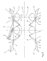
- the apparatus according to the invention comprises two rings 1 of support arms 2. These rings 1 and the tire to be produced are coaxial.
- the axially inner end 20 of the support arms 2 can be moved axially and radially; this means that the movement of said end 20 has at least one radial component and one axial component.
- Said end 20 supports means 3 for retaining the wire 4.
- the support arms 2 also comprise an articulation point 21 and a control point 22.
- the articulation points 21 of all the support arms 2 form a circle 210 of invariable diameter, coaxial with the tire to be manufactured, axially displaceable.
- the control points 22 can be moved, all simultaneously in each ring 1, axially with respect to the articulation points 21.
- the apparatus also comprises a rotary arm 5 whose axis of rotation 50 is substantially perpendicular to the axis of the crowns 1, and is preferably located radially outside the cylinder defined by the retaining means 3 of the wire 4. Said axis 50 is located axially approximately halfway between said retaining means 3.
- This rotary arm 5 is driven by a motor 55 by means of a control shaft 56. It is necessary that, at each turn of the rotary arm 5, the crowns 1 have rotated by an angle corresponding to the distance between two adjacent retaining means 3.
- a tapered tip 51 facilitates the passage of the end of the rotary arm 5 between two adjacent retaining means 3.
- the direction of rotation of the rotary arm 5 can be identified in FIG. 1 by this tapered tip 51 oriented in the direction of movement.
- the rotary arm 5 carries wire unwinding means essentially comprising, in this example, an orifice 52 for the output of the wire 4 situated behind the movement. Then, it is also possible to provide, between the end and the center of the rotary arm 5, a lug 53 lifting the wire relative to the rotary arm 5.
- the wire 4 is hooked to the retaining means 3 located above the rotary arm 5 which must therefore pass not through the space between the retaining means 3 where the wire is already hooked and the adjacent free retainer, but in the space between the first retainer retainer 3 still free and the following retainer.
- the order in which we have just spoken of the retaining means 3 corresponds to the order in which they must appear at the height of the rotary arm 5, which defines the direction of rotation of the two crowns 1, namely from bottom to top in Figure 1.
- the wire 4 is hooked to the retaining means 3 located below the rotary arm 5 which must therefore pass into the space between the retaining means 3 where the wire is already hooked and the free retainer adjacent.
- the rotary arm 5 has a recess 58 making it possible to adapt the distance separating the orifice 52 from the axis of rotation 50 to the distance separating the retaining means 3 from a crown 1 relative to the other, said gap being conditioned by the length of the section 40 of wire 4 to be laid.
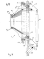
- the wire 4 is unwound from a reel 41 at a speed imposed by two rollers 90 supported one on the other and between which the wire 4 is introduced.
- the speed of these rollers is regulated by a motor 93, the speed of which is controlled by the average consumption of wire 4.
- the wire 4 passes through a system 91 ensuring a substantially constant tension and the necessary length compensation because the wire draw by the rotary arm 5 is variable.
- the system 91 shown operates thanks to a dry air pressure (air supply by the pipe 92) acting on the wire 4 passing between two parallel plates 910, slightly more spaced than necessary so that the wire 4 slides freely between them.
- the wire 4 forms a loop represented therein in broken lines whose average size is kept constant by the control controlling the speed of the motor 93.
- the wire 4 then joins the center of the rotary shaft 5 through a hole in the center of the control shaft 56, then joins the outlet orifice 52.
- the rubber layer with which the rigid core is coated immobilizes the sections 40 of wire 4 when they are placed on the core 7. It therefore participates in the anchoring of the wire 4.
- the anchoring of the wire 4 is also ensured by a rod as known per se.
- the wire 4 threaded into all the laying members constituted by the rotary arm 5, the control shaft 56, the tension compensating system 91 and the drive rollers 90, is first attached to a clamp 23 secured to one of the support arms 2 of the left crown 1 in FIG. 1.
- the rotary arm 5 at the rear end of which protrudes the wire 4 is moved back to height of the support arm 2 carrying the clamp 23.
- the crowns 1 of the support arm 2 are moved apart axially so that the clamp 23 grasps the wire 4 (as shown in FIG. 11), then takes the corresponding spacing in the position for hooking the wire 4 to the retaining means 3.
- Said head 65 comprises a ramp by which liquid polyethylene is brought to glue the sections of wires 40 ′ and 40" where they intersect, and it comprises knives 66 which are better visible in FIG. 12a (seen in the direction of the arrow "a” in FIG. 12), ensuring the shearing of the sections 40 'and 40 “joining respectively the clamp 23 and the outlet orifice 52 of the rotary arm 5.
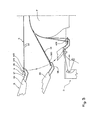
- the apparatus is provided with means making it possible to insert a core 7 radially inside the circle formed by the retaining means 3. During the positioning of the sections 40 of wire 4, this interior space must remain free so as not to hinder the movement of the rotary arm 5.
- Said means making it possible to insert a core 7 essentially consist of a free space 70 located radially inside one of the crowns 1 of the arm of support 2, said space 70 being greater than the size of the core 7, for at least one position of said support arms 2 and by an advance system (shown diagrammatically by an arrow 71 in FIG. 2) of the core 7 which introduces this inside and between the crowns 1 or extracts it out of its position between said crowns 1.
- the core previously coated with a layer of rubber constituting the inner skin of the tire and participating in the anchoring of the wires 4 is introduced inside the cylinder constituted by the sections 40 of wire 4.
- the core 7 is shown in solid lines in an intermediate position during its insertion and in broken lines the core 7 in the middle position between the rings 1.
- the representation in solid lines of the arms of support 2 corresponds to the position they occupy during the attachment of the wire 4 (see FIG. 1) and during the insertion of the core 7, while the drawing in broken lines shows a subsequent position of the same support arms 2 in progress drawdown.
- the superimposition in a same figure of these successive stages makes it possible to understand the movements to be carried out.
- recalling the movement of the rotary arm 5 in the same FIG. 2 makes it possible to appreciate the usefulness of the introduction of the core 7 after the production of the cylinder formed by the sections 40 of wire 4.
- the retaining means 3 are constituted by two hooks 31 and 32.
- the first hook 31 is necessary to ensure the attachment of the wire 4. It is therefore shaped so as to retain the wire 4 presented by the rotary arm 5.
- the projections in a radial plane of the end tip 310 are in opposite directions in one and the other crown 1.
- the second hook 32 is arranged so that, at this stage, each of the two sections 40 (superimposed on the upper part of FIG. 3) is arranged on either side of said second hook 32.
- the second hook 32 When the end 20 of the support arms 2 is folded radially inwards, and axially towards the core 7, the second hook 32, whose tip 320 is shaped for this purpose, hooks one of the sections 40 of wire 4 to initiate the formation of a loop 400. It will be noted that this folding is done by controlling the axial approximation of the articulation points 21 in a coordinated manner between the two crowns 1, while maintaining a thrust on the control points 22. This thrust balances the tension of the wires 4, the variations of which must preferably be limited (for example, variations in a ratio of one to two are satisfactory).
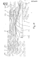
- FIG. 9 makes it possible to understand clearly how this thrust can be produced so that the tension in the wire 4 is substantially constant, whatever the inclination of the sections 40 relative to the ends 20 of the support arms 2 (see FIG. 2).
- the articulation points 21 of the support arms 2 are, for each crown 1, integral with a plate 215. These two plates 215 can be approached or distant from each other, preferably symmetrically.
- the control points 22 of each ring 1 are all immobilized axially with respect to a plate 225 and can move radially along these said plates 225.
- the relative spacing of the plates 215 and 225 controls the tilting of the support arms 2 while the axial position of the plates 215 determines the axial position of each ring 1 of support arms 2.
- this thrust is variable. It must be all the smaller as the sections 40 form a greater angle with the end 20 of the support arms 2. This thrust is obtained by adapting the length of the rocker arms 27, the angles formed by the rocker arms 27, as well as the relative angles between the rockers 27 and the rods' 28.
- the few profile turns thus constitute a bead wire 45.
- said profile has a curved shape, the convex part of which is oriented radially towards the axis of rotation of the tire during manufacture. In this way, the successive turns are very easily superimposed on each other.
- the apparatus according to the invention also comprises (see FIGS. 4 to 8) a device 8 used when anchoring the wire 4 to a rod 45 on each side of the core 7.
- the use of this device 8 is adapted to the form hooks 31 and 32, the points 310 and 320 of which are oriented axially in opposite directions, which conditions the movements during stalling.
- This device 8 comprises several assemblies 80, preferably at least fifty on the circumference. These assemblies 80 are integral with each other and axially movable (simultaneously). They essentially consist of a straight rod 81, parallel to the axis of the crowns 1, therefore to the axis of the core 7, that is to say to the axis of the tire during manufacture, and a tilting finger 82.
- the width of the core 7 at the rods 45 being less than the maximum width, there are two positions corresponding to the retention by a rod 45 of the tensioned wires 4: one against the core 7, which is the final position of the rod 45 and another spaced from the core 7. The folding of the retaining means 3 is stopped at the first encountered of these positions.
- the anchoring device 8 is brought axially close to the core 7 (see FIG. 4) so that the straight rods 81 close a quadrilateral, moreover formed by the wire 4, that is to say, block the opening of certain loops 400 and determines the outside diameter of the rods 45.
- the rod 45 is then terminated by staples enclosing the profile layers at several places on the circumference and particularly in the overlap areas of the beginning and the end of the spiral formed by said profile, or by any suitable fixing means.
- the hooks 31 and 32 can then be released.
- the core 7 carrying the reinforcement anchored to rods can be removed from the device.
- the manufacture of the tire is continued, where appropriate by the production of other reinforcements also constituting the carcass reinforcement, by the fitting of the crown reinforcements (belt), the sidewalls and the tread.
- the rotary arm 5 shown in FIGS. 13 and 14 is telescopic so that the length separating the outlet orifice 52 from the axis of rotation 50 can automatically adapt to the dimension " of the tire to be manufactured.
- a cable control is used to shorten said length and a rod and ball control to lengthen it.
- Said length therefore varies as half the axial spacing between the retaining means 3 of a crown 1 relative to the axially opposite crown 1, and this in the range where the variation of this spacing corresponds to the adjustment of the machine according to the dimension of the tire to be manufactured, or more precisely, as regards the construction of a reinforcement for a tire, depending on the size of the section 40 of wire 4 to be attached to the retaining means 3.
- said rings 1 can move axially towards one another beyond the adjustment range, without the length of the telescopic rotary arm 5a being modified.
- the orientation of the tip 320a is substantially identical to the orientation of the tip 310a whereas in the embodiment described above, the orientations of the tips 310 and 320 diverged notably.
- Figures 13 and 14 are views in planes perpendicular to each other. It can be seen there that the orientation of said points 310a and 320a is axially towards the outside of the machine, tangentially in opposite directions (see FIG. 14), radially towards the inside for the crown 1 on the right in FIG. 14, it that is to say on the side where the rotary arm 5 penetrates inside the cylinder formed by the sections 40 of wire 4, and radially outwards for the crown 1 on the left in FIG. 14, that is to say -to say on the side where the rotary arm 5 leaves the cylinder formed by the sections 40 of wire 4.
- the tip of said hooks (310, 320, 310a, 320a) is located outside the plane in which the base of said hooks is included .
- the retaining means 3 (hooks 3la and 32a) are therefore interchangeable between the two crowns 1.
- the design of these retaining means 3 and the presentation of the wire 4 on said retaining means 3 is decisive so that the sections 40 of wire 4 form a figure in "S" and not in “8” when they define said cylinder of sections 40. This means that there cannot be radially overlapping of wires.
- FIG. 15 also makes it possible to clearly see how the wire 4 should be presented to the retaining means 3 on the right and how said wire 4 is arranged on all the retaining means 3.
- the wire 4 is presented the retaining means 3 while the rotary arm 5 leaves the plane of the figure, passes above the retaining means 3 still free, the lug 53a being in the lowered position.
- lug 53a is raised by the action of a rod 530a urged by a cam 531a to present the wire 4 raised in front of the crown 1 on the right as shown in FIG. 14.
- the lug 53a On the axially opposite side, the lug 53a, in position rest, lift the wire a lot less 4.
- the rotary arm 5 carrying the lug 53a being telescopic, said rod 530a must of course also be telescopic.
- the design of the retaining means 3 of this alternative embodiment allows the attachment of the wire 4, then allows the formation of a loop 400 during the folding as explained above, while allowing the detachment of the retaining means 3 after insertion of a rod 45.
- the drawdown is similar in its general principle to that set out above. The differences essentially relate to the detachment of the retaining means 3 (see FIGS. 16 to 18).
- the device comprises, on each side of the core, a device 8a essentially comprising a plurality of blades 85a movable axially simultaneously and radially simultaneously while remaining parallel to the axis of the crowns 1.
- These blades 85a comprise a housing 850a oriented radially towards the inside.
- This housing 850a inserted between the sections 40 of wire 4 to close a quadrilateral also formed by the wire 4 having formed the loops 400, determines the outside diameter of the rod.
- These housings 850a therefore guide the insertion of the rod.
- the wire 4 is released from the retaining means 3 with the help of the blades 85a.
- the rod 45 being held axially by the housings 850a of the blades 85a, the two rings 1 are brought axially closer to one another.
- the support arms 2 therefore advance axially towards the center of the core 7 which, the wires 4 being held by the rod 45 immobilized by the blades 85a, ensures the release of the hooks 31a and 32a whose points 310a and 320a are here oriented in the same way.
- the thrust applied to the control points 22 therefore causes the complete tilting of the support arms 2.
- the sections 40 of wire 4 are pressed against the core 7 under the effect of springs 25.
- These springs 25 are in the shape of a "U", the substantially parallel and flexible branches of which are each secured to a support arm 2 and the base branch 250 of which constantly presses against the sections 40 of wire 4. Thanks to these springs 25, the sections 40 constituting the carcass reinforcement remain taut after the detachment of the retaining means 3.
- the blades 85a are then lifted, moved back axially, then lowered axially outside the rod 45.
- the rod 45 can then be advanced axially to its final position against the core 7.
- this movement is accompanied by an axial approximation of the rings 1 of the support arm 2, so that the base branch 250 of the springs 25 can apply the sections 40 of wire 4 against the core 7.
- the springs 25 are attached to the support arm 2 in such a way that the axial movement of the rings 1 towards the core 7 causes the base branches 250 to descend radially while skirting the core 7.
- the method and the device described make it possible to make reinforcements in which the wires 4 arranged in the sides are radial or not, and in which the wires 4 disposed under the tread are parallel to the axis or not. It is possible, if necessary, to modify the angular position of the crowns 1 relative to each other before and / or during the folding down to obtain the desired architecture for the reinforcement.
- the tire obtained by the means illustrating the invention comprises a carcass reinforcement without turning over, in contrast to the arrangement universally adopted at present in the tire industry where the carcass reinforcement is turned around around the bead wires.
- the invention also makes it possible to produce such reversals by adapting the spacing of the retaining means 3 and their folding down around the core 7.
Abstract
Description
La présente invention se rapporte à la fabrication des pneumatiques. Plus particulièrement, elle concerne un procédé et un appareil de fabrication de renforcements pour pneumatiques.The present invention relates to the manufacture of tires. More particularly, it relates to a method and an apparatus for manufacturing reinforcements for tires.
Les pneumatiques sont renforcés notamment par au moins une nappe dite de carcasse, à l'heure actuelle le plus souvent disposée radialement, ancrée dans chacun des deux bourrelets à au moins une tringle. Les nappes comportent une pluralité de fils adjacents qui, dans le cas des carcasses radiales, sont approximativement inclus dans un plan passant par l'axe de rotation du pneumatique.The tires are reinforced in particular by at least one so-called carcass ply, currently most often arranged radially, anchored in each of the two beads with at least one bead wire. The plies comprise a plurality of adjacent cords which, in the case of radial carcasses, are approximately included in a plane passing through the axis of rotation of the tire.
Le terme "fil" doit être compris dans le sens le plus général, à savoir aussi bien un fil unitaire qu'un câble formé par l'assemblage de plusieurs fils unitaires, ou un assemblage équivalent.The term "wire" should be understood in the most general sense, namely both a unitary wire and a cable formed by the assembly of several unitary wires, or an equivalent assembly.
Dans la technique antérieure, le procédé le plus usuel consiste à préparer, à partir d'un grand nombre de bobines de fils déroulées simultanément, des nappes dont les fils sont orientés parallèlement à leur plus grande longueur et sont enrobés dans du caoutchouc. Ces nappes sont ensuite coupées selon un angle voulu, par exemple un angle droit, en morceaux de longueur appropriée, puis ces morceaux de nappes sont aboutés par leurs tranches parallèles aux fils, avec ou sans superposition de. fils, pour former des produits intermédiaires ou semi-finis utilisés lors de la fabrication du pneumatique proprement dite. La fabrication de tels produits semi-finis est illustrée par exemple par le brevet US 3 573 135. Ce procédé requiert un outillage coûteux et impose de fabriquer un grand nombre de nappes différentes en fonction des largeurs de nappes nécessitées par les dimensions de pneumatiques à réaliser. D'après l'état de la technique, on connait également d'autres façons de préparer les renforcements pour pneumatiques. Selon l'une des façons, le ou les fils de renforcement sont disposés autour d'un noyau définissant la surface intérieure du pneumatique, l'un après l'autre et en continu, pour former un renforcement pour pneumatique. On en trouve des exemples dans les brevets US 852 855, US 1 328 006 ou US 1 321 402. Cependant, la mécanisation de la pose du fil autour d'un noyau est très complexe du fait que le fil se développe dans des directions axiales, radiales, axiales et radiales dans l'espace extérieur audit noyau.In the prior art, the most usual method consists in preparing, from a large number of coils of threads unwound simultaneously, sheets whose threads are oriented parallel to their greatest length and are coated in rubber. These plies are then cut at a desired angle, for example a right angle, into pieces of appropriate length, then these pieces of plies are butted by their edges parallel to the wires, with or without superposition of. wires, to form intermediate or semi-finished products used during the manufacture of the tire itself. The manufacture of such semi-finished products is illustrated, for example, by US Pat. No. 3,573,135. This process requires expensive tools and makes it necessary to manufacture a large number of different plies depending on the widths of plies required by the dimensions of the tires to be produced. . From the state of the art, other ways of preparing reinforcements for tires are also known. In one of the ways, the reinforcement wire or wires are arranged around a core defining the interior surface of the tire, one after the other and continuously, to form a reinforcement for the tire. Examples are found in patents US 852 855, US 1 328 006 or US 1 321 402. However, the mechanization of the laying of the wire around a core is very complex because the wire develops in axial directions , radial, axial and radial in the space outside said core.
Selon un autre principe, le fil de renforcement est enroulé autour de deux tringles ayant leur forme circulaire finale, ou bien encore fendues et disposées à plat pendant que l'on enroule le fil. Ceci est illustré par exemple par les brevets W083/02749, US 2 139 840 ou US 1 349 390. Là encore, le procédé présente de nombreux inconvénients liés au fait que l'on construit un renforcement très éloigné de sa forme finale dans le pneumatique, particulièrement s'il est construit à plat. Dans le cas où ledit renforcement est construit autour de tringles circulaires, il faut effectuer une conformation par élévation radiale de la zone médiane des fils disposés entre deux tringles, ce qui se fait habituellement au moyen de dispositifs pneumatiques, donc peu précis du point de vue du respect des géométries.According to another principle, the reinforcing wire is wound around two rods having their final circular shape, or else slit and arranged flat while the wire is wound. This is illustrated for example by patents WO83 / 02749, US 2,139,840 or US 1,349,390. Here again, the method has many drawbacks linked to the fact that a reinforcement is constructed very far from its final shape in the tire. , especially if it is built flat. In the case where said reinforcement is constructed around circular rods, it is necessary to carry out a conformation by radial elevation of the middle zone of the wires disposed between two rods, which is usually done by means of pneumatic devices, therefore imprecise from the point of view respect for geometries.
Ces techniques connues de fabrication d'un renforcement pour pneumatiques à partir d'un seul fil sont donc complexes et peu performantes.These known techniques for manufacturing a reinforcement for tires from a single wire are therefore complex and ineffective.
Le but de la présente invention est de proposer un procédé de réalisation d'un renforcement non plus à partir de produits semi-finis sous forme de nappe mais à partir d'un seul fil, qui ne présente pas les inconvénients des procédés antérieurs. L'invention se rapporte à la manière selon laquelle le fil est disposé pour constituer ledit renforcement.The object of the present invention is to propose a process for producing a reinforcement no longer from semi-finished products in the form of a sheet but from a single thread, which does not have the drawbacks of the previous processes. The invention relates to the manner in which the wire is arranged to constitute said reinforcement.
Selon l'invention, le procédé de fabrication d'un renforcement pour pneumatique est caractérisé en ce que
- a) un fil continu est accroché à des moyens de retenue disposés en deux cercles séparés d'une distance correspondant à la longueur du trajet d'un fil d'un côté à l'autre du renforcement, de sorte que le fil ainsi disposé définit un cylindre par une pluralité d'allers et retours d'un moyen de retenue à un autre,
- b) par un mouvement approprié des moyens de retenue, le fil ainsi disposé est rabattu sur et autour d'un noyau rigide définissant la forme de la surface intérieure du pneumatique,
- c) l'ancrage du fil étant assuré, les moyens de retenue sont dégagés.
- a) a continuous wire is attached to retaining means arranged in two circles separated by a distance corresponding to the length of the path of a wire from one side to the other of the reinforcement, so that the wire thus arranged defines a cylinder by a plurality of back and forth from one retaining means to another,
- b) by an appropriate movement of the retaining means, the wire thus disposed is folded over and around a rigid core defining the shape of the inner surface of the tire,
- c) the anchoring of the wire being ensured, the retaining means are released.
La solution selon l'invention consiste donc à construire un cylindre constitué de tronçons de fils de renforcement sensiblement parallèles à l'axe dudit cylindre, retenus à chaque extrémité par des moyens de retenue, le renforcement complet étant constitué d'un seul fil continu accroché à tous les moyens de retenue ; ensuite, les moyens de retenue des fils sont déplacés de manière à ce que le renforcement ainsi constitué entoure un noyau rigide définissant la surface intérieure du pneumatique, c'est-à-dire de manière à ce que ledit renforcement prenne sa place dans le futur pneumatique.The solution according to the invention therefore consists in building a cylinder made up of sections of reinforcing wires substantially parallel to the axis of said cylinder, retained at each end by retaining means, the complete reinforcement consisting of a single continuous wire hooked all means of restraint; then, the wire retaining means are moved so that the reinforcement thus formed surrounds a rigid core defining the inner surface of the tire, that is to say so that said reinforcement takes its place in the future pneumatic.
Le terme "-fil" est utilisé pour désigner le matériau de renforcement en général alors que "tronçon de fil" désigne plus précisément la quantité de fil disposée entre deux moyens de retenue situés de part et d'autre du noyau.The term "-wire" is used to designate the reinforcement material in general, while "section of wire" more precisely designates the quantity of wire placed between two retaining means located on either side of the core.
L'ancrage du fil doit être réalisé par tout moyen compte tenu de la fonction du renforcement. Lorsque ledit renforcement est une armature de carcasse de pneumatique, l'ancrage doit permettre à ladite carcasse ainsi réalisée de résister à la pression de gonflage du pneumatique. On utilisera par exemple une tringle.The anchoring of the wire must be carried out by any means taking into account the function of the reinforcement. When said reinforcement is a tire carcass reinforcement, the anchoring must allow said carcass thus produced to resist the inflation pressure of the tire. We will use for example a rod.
Grâce à ce procédé, la constitution d'un renforcement par accrochage d'un fil à des moyens de retenue se fait dans une configuration simple où tous les tronçons de fils entre deux moyens de retenue sont disposés sensiblement parallèlement entre eux pour former un cylindre à axe parallèle à l'orientation desdits tronçons. De manière équivalente, les cercles formés par les moyens de retenue peuvent être de diamètres légèrement différents, de-sorte que les tronçons de fil définissent alors un tronc de cône.Thanks to this method, the constitution of a reinforcement by hooking a wire to retaining means is done in a simple configuration where all the sections of wire between two retaining means are arranged substantially parallel to each other to form a cylinder with axis parallel to the orientation of said sections. Equivalently, the circles formed by the retaining means may be of slightly different diameters, so that the sections of wire then define a truncated cone.
Ainsi donc, grâce au recours auxdits moyens de retenue du fil, on peut débuter de manière très simple la construction d'un renforcement que l'on disposera autour d'un noyau rigide, le recours à un noyau rigide étant très favorable au point de vue régularité et précision de fabrication. Par "noyau rigide", on entend un noyau substantiellement non déformable, par exemple du genre de ceux que l'on trouve dans les moules utilisés pour la fabrication de pneumatiques en polyuréthanne, comme illustré par le brevet US 4 279 856.Thus, thanks to the use of said wire retaining means, it is possible to begin in a very simple manner the construction of a reinforcement which will be placed around a rigid core, the use of a rigid core being very favorable to the point of regularity and manufacturing precision. By "rigid core" is meant a substantially non-deformable core, for example of the kind found in the molds used for the manufacture of polyurethane tires, as illustrated by US Pat. No. 4,279,856.
L'illustration de l'invention faite dans la suite montre la fabrication d'une armature de carcasse en rayonne pour pneumatique pour véhicule de tourisme. Cependant, il est bien évident que la portée de l'invention ne se limite pas à la fabrication de ce seul type de renforcement, ni à ce seul type de fil, mais peut également trouver un champ d'application pour les ceintures de pneumatique.The illustration of the invention made below shows the manufacture of a rayon carcass reinforcement for a tire for a passenger vehicle. However, it is obvious that the scope of the invention is not limited to the manufacture of this single type of reinforcement, nor to this single type of wire, but can also find a field of application for tire belts.
Grâce à l'invention, il est possible de débuter la fabrication d'une armature de carcasse immédiatement en forme circulaire tout en s'affranchissant du diamètre des tringles du futur pneumatique.Thanks to the invention, it is possible to start manufacturing a carcass reinforcement immediately in circular shape while overcoming the diameter of the beads of the future tire.
Les figures jointes illustrent l'invention de manière non limitative ; elles permettent d'en bien comprendre le fonctionnement et d'en saisir tous les avantages.
- La figure 1 est une perspective montrant la disposition générale d'une machine selon l'invention.
- La figure 2 est une coupe montrant la disposition de différents organes à différents stades.
- La figure 3 illustre un mouvement particulier.
- Les figures 4 à 8 illustrent l'ancrage de l'armature de carcasse à une tringle.
- La figure 9 montre la commande des mouvements de certains organes de la machine.
- Les figures 10 et 11 montrent en détail le départ du cycle de fonctionnement de la machine.
- Les figures 12 et 12a montrent la fin du cycle de fonctionnement de la machine.
- Les figures 13 et 14 sont des vues dans des plans perpendiculaires l'un de l'autre de certains organes de la machine.
- La figure 15 illustre une configuration du renforcement en cours de fabrication.
- Les figures 16 à 18 illustrent une variante de réalisation de l'invention.
- Figure 1 is a perspective showing the general arrangement of a machine according to the invention.
- Figure 2 is a section showing the arrangement of different organs at different stages.
- Figure 3 illustrates a particular movement.
- Figures 4 to 8 illustrate the anchoring of the carcass reinforcement to a rod.
- Figure 9 shows the control of the movements of certain parts of the machine.
- Figures 10 and 11 show in detail the start of the machine operating cycle.
- Figures 12 and 12a show the end of the machine operating cycle.
- Figures 13 and 14 are views in planes perpendicular to each other of certain parts of the machine.
- FIG. 15 illustrates a configuration of the reinforcement during manufacture.
- Figures 16 to 18 illustrate an alternative embodiment of the invention.
L'appareil selon l'invention, dont on voit la présentation générale des organes principaux à la figure 1, comporte deux couronnes 1 de bras de support 2. Ces couronnes 1 et le pneumatique à fabriquer sont coaxiaux. L'extrémité 20 axialement intérieure des bras de support 2 peut être déplacée axialement et radialement ; cela signifie que le mouvement de ladite extrémité 20 a au moins une composante radiale et une composante axiale. Ladite extrémité 20 supporte des moyens de retenue 3 du fil 4.. Les bras de support 2 comportent en outre un point d'articulation 21 et un point de commande 22. Les points d'articulation 21 de tous les bras de support 2 forment un cercle 210 de diamètre invariable, coaxial au pneumatique à fabriquer, déplaçable axialement. Les points de commande 22 peuvent être déplacés, tous simultanément dans chaque couronne 1, axialement par rapport aux points d'articulation 21. Ces deux mouvements (déplacement axial des points d'articulation 21 et déplacement des points de commande 22 par rapport aux points d'articulation 21) permettent de conférer aux bras de support 2 les mouvements voulus pour que leurs extrémités 20 puissent décrire le mouvement voulu lors du rabattement du fil 4 autour d'un noyau. Le rabattement autour d'un noyau est expliqué en détails plus loin. Lesdites extrémités 20 forment donc un cercle coaxial au pneumatique à fabriquer, de rayon variable et de position axiale variable pour pouvoir procéder au rabattement du fil sur et autour d'un noyau. La position axiale variable permet en plus de s'adapter à différentes longueurs de tronçon de fil. On aperçoit que les deux couronnes 1 sont symétriques ; cependant, cette symétrie n'est pas indispensable, elle est simplement fort commode pour réaliser un pneumatique dont l'architecture est symétrique. De préférence, les mouvements des deux couronnes sont coordonnés et symétriques.The apparatus according to the invention, the general presentation of the main members of which can be seen in FIG. 1, comprises two
L'appareil comporte également un bras rotatif 5 dont l'axe de rotation 50 est sensiblement perpendiculaire à l'axe des couronnes 1, et est de préférence situé radialement à l'extérieur du cylindre défini par les moyens de retenue 3 du fil 4. Ledit axe 50 est situé axialement sensiblement à mi-distance entre lesdits moyens de retenue 3. Ce bras rotatif 5 est entraîné par un moteur 55 par l'intermédiaire d'un arbre de commande 56. Il faut que, à chaque tour de bras rotatif 5, les couronnes 1 aient tourné d'un angle correspondant à l'écart entre deux moyens de retenue 3 adjacents. Une pointe effilée 51 facilite le passage de l'extrémité du bras rotatif 5 entre deux moyens de retenue 3 adjacents. Le sens de rotation du bras rotatif 5 est repérable sur la figure 1 par cette pointe effilée 51 orientée dans le sens du mouvement. Le bras rotatif 5 porte des moyens de dévidage de fil comportant essentiellement, dans cet exemple, un orifice 52 de sortie du fil 4 situé en arrière par rapport au mouvement. Puis, on peut également prévoir, entre l'extrémité et le centre du bras rotatif 5, un ergot 53 soulevant le fil par rapport au bras rotatif 5.The apparatus also comprises a
A la couronne 1 de droite à la figure 1, le fil 4 est accroché au moyen de retenue 3 situé au dessus du bras rotatif 5 qui doit donc passer non pas dans l'espace situé entre le moyen de retenue 3 où le fil est déjà accroché et le moyen de retenue libre adjacent, mais dans l'espace entre le premier moyen de retenue 3 encore libre et le moyen de retenue suivant. L'ordre dans lequel on vient de parler des moyens de retenue 3 correspond à l'ordre dans lequel ils doivent apparaître à hauteur du bras rotatif 5, ce qui définit le sens de rotation des deux couronnes 1, à savoir de bas vers le haut sur la figure 1. A la couronne 1 de gauche à la figure 1, le fil 4 est accroché au moyen de retenue 3 situé au dessous du bras rotatif 5 qui doit donc passer dans l'espace situé entre le moyen de retenue 3 où le fil est déjà accroché et le moyen de retenue libre adjacent.At the
Au centre du bras rotatif 5, se trouve fixé un élément de maintien 54 de la tension du fil 4 ; du fait que l'axe de rotation 50 est radialement à l'extérieur du cylindre défini par les moyens de retenue 3, l'accrochage du fil sur les moyens de retenue 3 situés à droite sur la figure 1 se fait à un endroit de la trajectoire de l'orifice 52 au-delà du point où le mouvement dudit orifice 52 a provoqué l'appel d'une longueur maximale du fil 4, à savoir un tronçon 40 de fil 4. Ce point est sur la droite définie par le dernier moyen de retenue 3 où le fil 4 est accroché et l'endroit 57 où le fil sort de l'arbre de commande 56. Ledit élément de maintien 54 constitué dans cet exemple par une tige courbe doit être conformée de manière à libérer le fil 4 dès qu'il n'est plus nécessaire de le retenir. Un tel élément de maintien 54 n'est pas toujours indispensable lorsque les moyens de compensation de longueur prévus par ailleurs suffisent à garantir que le fil 4 est toujours tendu.In the center of the
En son centre, le bras rotatif 5 comporte un évidement 58 permettant d'adapter la distance séparant l'orifice 52 de l'axe de rotation 50 à l'écart séparant les moyens de retenue 3 d'une couronne 1 par rapport à l'autre, ledit écart étant conditionné par la longueur du tronçon 40 de fil 4 à poser.In its center, the
Afin de garantir une présentation adéquate des bras de support 2 par rapport au bras rotatif 5, on peut prévoir, de chaque côté, un arbre 6 portant une cannelure 60 hélicoïdale engrenée sur les bras de support 2 et ceci, au voisinage immédiat de la trajectoire du bras rotatif 5. Ainsi, le positionnement de l'extrémité 20 des bras de support 2 est affermi pendant le passage du bras rotatif 5. Bien sûr, la rotation de ces arbres 6 est synchronisée avec celle du bras rotatif 5, par la transmission par courroies crantées 61.In order to guarantee an adequate presentation of the
Le fil 4 est déroulé hors d'une bobine 41 à une vitesse imposée par deux rouleaux 90 appuyés l'un sur l'autre et entre lesquels le fil 4 est introduit. La vitesse de ces rouleaux est réglée par un moteur 93 dont la vitesse est asservie à la consommation moyenne de fil 4. Ensuite, le fil 4 passe dans un sytème 91 assurant une tension sensiblement constante et la compensation de longueur nécessaire du fait que l'appel de fil par le bras rotatif 5 est variable. Le système 91 représenté fonctionne grâce à une pression d'air sec (alimentation en air par le tuyau 92) agissant sur le fil 4 passant entre deux plaques 910 parallèles, légèrement plus espacées que nécessaire pour que le fil 4 glisse librement entre elles. Le fil 4 y forme une boucle représentée en traits discontinus dont la grandeur moyenne est maintenue constante par l'asservissement commandant la vitesse du moteur 93. Le fil 4 rejoint ensuite le centre de l'arbre rotatif 5 par un trou aménagé au centre de l'arbre de commande 56, puis rejoint l'orifice de sortie 52.The
Selon l'invention, le procédé de fabrication d'un pneumatique est caractérisé en ce que :
- a) d'une part, une ou plusieurs couche(s) de caoutchouc est(sont) appliquée(s) sur
un noyau rigide 7 définissant la forme de la surface intérieure du pneumatique, et d'autrepart un fil 4 continu est accroché à des moyens de retenue 3 disposés en deux cercles séparés d'une distance correspondant à la longueur du trajet d'un fil 4 d'un côté à l'autre du renforcement de sorte que le fil 4 ainsi disposé définit un cylindre par une pluralité d'aller et de retours d'un moyen de retenue 3 à un autre, - b) ledit noyau rigide 7 est inséré à l'intérieur dudit cylindre,
- c) par un mouvement approprié des moyens de retenue 3, le fil 4 ainsi disposé est rabattu sur et autour dudit noyau 7,
- d) l'ancrage du fil étant assuré, les moyens de retenue 3 sont dégagés,
- e) la fabrication du pneumatique est poursuivie.
- a) on the one hand, one or more layer (s) of rubber is (are) applied (s) to a
rigid core 7 defining the shape of the inner surface of the tire, and on the other hand acontinuous wire 4 is hooked to retaining means 3 arranged in two circles separated by a distance corresponding to the length of the path of awire 4 from one side to the other of the reinforcement so that thewire 4 thus arranged defines a cylinder by a plurality back and forth from onerestraint 3 to another, - b) said
rigid core 7 is inserted inside said cylinder, - c) by an appropriate movement of the retaining means 3, the
wire 4 thus disposed is folded over and around saidcore 7, - d) the anchoring of the wire being ensured, the retaining means 3 are released,
- e) the manufacture of the tire is continued.
La couche de caoutchouc dont est revêtu le noyau rigide immobilise les tronçons 40 de fil 4 lorsqu'ils sont posés sur le noyau 7. Elle participe donc à l'ancrage du fil 4. L'ancrage du fil 4 est également assuré par une tringle comme connu en soi.The rubber layer with which the rigid core is coated immobilizes the
Après cette présentation générale, on va maintenant décrire l'invention plus en détail en suivant le cycle de fabrication d'un renforcement.After this general presentation, the invention will now be described in more detail by following the manufacturing cycle of a reinforcement.
Pour débuter la fabrication du renforcement, le fil 4, enfilé dans tous les organes de pose constitués par le bras rotatif 5, l'arbre de commande 56, le sytème 91 compensateur de tension et les rouleaux 90 d'entraînement, est d'abord accroché à une pince 23 solidaire de l'un des bras de support 2 de la couronne 1 de gauche sur la figure 1. Comme représenté à la figure 10, le bras rotatif 5 à l'extrémité arrière duquel dépasse le fil 4 est reculé à hauteur du bras de support 2 portant la pince 23. Puis on écarte axialement les couronnes 1 de bras de support 2 de manière à ce que la pince 23 saisisse le fil 4 (comme montré à la figure 11), puis prennent l'écartement correspondant à la position d'accrochage du fil 4 aux moyens de retenue 3.To begin manufacturing the reinforcement, the
L'extrémité libre du fil 4 étant ainsi maintenue au voisinage des moyens de retenue 3 que le bras rotatif 5 vient juste de laisser au dessus et derrière lui, la rotation dudit bras rotatif 5 provoque l'appel de la quantité de fil 4 nécessaire à la réalisation progressive du renforcement en accrochant le fil 4 successivement à tous les moyens de retenue 3, en effectuant autant de tours qu'il y a de moyens de retenue 3 sur une couronne 1, réalisant ainsi un cylindre formé d'autant de tronçons 40 de fil 4 qu'il y a de moyens de retenue 3 sur les deux couronnes 1. A titre d'exemple pour réaliser l'armature de carcasse en rayonne d'un pneumatique pour véhicules de tourisme, on utilise des couronnes 1 comportant de 500 à 700 moyens de retenue 3.The free end of the
Lorsque le fil 4 est accroché à tous les moyens de retenue 3, un cylindre complet est formé par les tronçons 40 du fil 4 ; le fil 4 est solidarisé au tronçon 40' de fil 4 rejoignant la pince 23, par exemple par un point de colle, puis il est coupé.When the
A cette fin, on voit à la figure 12 que la rotation du bras rotatif 5 est arrêtée lorsque le fil 4 est retenu par l'élément de maintien 54 constitué ici par une prohéminence cylindrique dont la face supérieure est un plan incliné. Ensuite un poussoir 65 soulève le fil 4 pour le libérer dudit élément de maintien 54. Sous l'action du système 91 compensateur de tension, le fil 4 se tend pour former un tronçon 40" rectiligne entre l'orifice 52 de sortie du bras rotatif 5 et le dernier moyen de retenue 3 auquel le fil 4 a été accroché. Ce tronçon 40" et celui 40' rejoignant la pince 23 se croisent alors à l'aplomb d'une tête 65, qui est approchée contre lesdits tronçons 40' et 40". Ladite tête 65 comporte une rampe par laquelle on amène du polyéthylène liquifié pour coller les tronçons de fils 40' et 40" là où ils se croisent, et elle comporte des couteaux 66 mieux visibles à la figure 12a (vue dans le sens de la flèche "a" à la figure 12), assurant le cisaillement des tronçons 40' et 40" rejoignant respectivement la pince 23 et l'orifice de sortie 52 du bras rotatif 5.To this end, it can be seen in FIG. 12 that the rotation of the
En consultant la figure 2, on voit que l'appareil est pourvu de moyens permettant d'insérer un noyau 7 radialement à l'intérieur du cercle formé par les moyens de retenue 3. Pendant la mise en place des tronçons 40 de fil 4, cet espace intérieur doit rester libre pour ne pas gêner le mouvement du bras rotatif 5. Lesdits moyens permettant d'insérer un noyau 7 sont essentiellement constitués par un espace libre 70 situé radialement à l'intérieur de l'une des couronnes 1 de bras de support 2, ledit espace 70 étant plus grand que l'encombrement du noyau 7, pour au moins une position desdits bras de support 2 et par un système d'avancée (schématisé par une flèche 71 à la figure 2) du noyau 7 qui introduit celui-ci à l'intérieur des et entre les couronnes 1 ou l'extrait hors de sa position entre lesdites couronnes 1.By consulting FIG. 2, it can be seen that the apparatus is provided with means making it possible to insert a
Lorsque la phase de mise en place des tronçons 40 de fil 4 est terminée, le noyau préalablement revêtu d'une couche de caoutchouc constituant la peau intérieure du pneumatique et participant à l'ancrage des fils 4, est introduit à l'intérieur du cylindre constitué par les tronçons 40 de fil 4. On a représenté en traits pleins le noyau 7 dans une position intermédiaire pendant son insertion et en traits discontinus le noyau 7 en position médiane entre les couronnes 1. De même la représentation en traits pleins des bras de support 2 correspond à la position qu'ils occupent pendant l'accrochage du fil 4 (voir figure 1) et pendant l'insertion du noyau 7, alors que le tracé en traits discontinus montre une position ultérieure des mêmes bras de support 2 en cours de rabattement. La superposition dans une même figure de ces stades successifs permet de bien comprendre les mouvements à réaliser. De même, le rappel du mouvement du bras rotatif 5 sur la même figure 2 permet de bien se rendre compte de l'utilité de l'introduction du noyau 7 après la réalisation du cylindre constitué par les tronçons 40 de fil 4.When the phase of fitting the
Si l'on ne prévoit pas cette insertion par l'intérieur d'une des deux couronnes 1, on est conduit à réaliser le cylindre de tronçons 40 de fil 4 alors que le noyau 7 se trouve déjà axialement entre les deux couronnes 1, ce qui obligerait donc à réaliser ledit cylindre à une position diamétrale exagérément agrandie pour ne pas gêner le mouvement du bras rotatif 5. Cela aboutirait à un appareil encombrant et allongerait le mouvement de rabattement des bras de support 2, mouvement qui est expliqué plus en détail ci-dessous.If this insertion is not provided from the inside of one of the two
A la figure 3, on voit que les moyens de retenue 3 sont constitués par deux crochets 31 et 32. Dans la phase de fabrication expliquée ci-dessus, seul le premier crochet 31 est nécessaire pour assurer l'accrochage du fil 4. Il est donc conformé de manière à retenir le fil 4 présenté par le bras rotatif 5. On notera que les projections dans un plan radial de la pointe 310 d'extrémité sont de sens opposés dans l'une et l'autre couronne 1. Le second crochet 32 est disposé de manière telle que, à ce stade, chacun des deux tronçons 40 (superposés à la partie supérieure de la figure 3) est disposé de part et d'autre dudit second crochet 32.In FIG. 3, it can be seen that the retaining means 3 are constituted by two
Lors du rabattement de l'extrémité 20 des bras de support 2 radialement vers l'intérieur, et axialement vers le noyau 7, le second crochet 32, dont la pointe 320 est conformée à cette fin, accroche l'un des tronçons 40 de fil 4 pour amorcer la formation d'une boucle 400. On notera que ce rabattement se fait en commandant le rapprochement axial des points d'articulation 21 de manière coordonnée entre les deux couronnes 1, tout en maintenant une poussée sur les points de commande 22. Cette poussée équilibre la tension des fils 4 dont les variations doivent de préférence être limitées (par exemple, des variations dans un rapport de un à deux sont satisfaisantes). De la sorte, dès qu'il y a rapprochement axial des couronnes 1, il y a automatiquement basculement des extrémités 20 des bras de support 2 radialement vers l'intérieur pour maintenir la tension dans les fils 4. Ainsi, ce sont les fils 4 eux-mêmes qui définissent la trajectoire des moyens de retenue 3 au cours du rabattement des bras de support 2 autour du noyau 7.When the
La figure 9 permet de bien comprendre comment on peut réaliser ladite poussée pour que la tension dans le fil 4 soit sensiblement constante, quelle que soit l'inclinaison des tronçons 40 par rapport aux extrémités 20 des bras de support 2 (voir figure 2). Les points d'articulation 21 des bras de support 2 sont, pour chaque couronne 1, solidaires d'un plateau 215. Ces deux plateaux 215 peuvent être approchés ou éloignés l'un de l'autre, de préférence de façon symétrique. Les points de commandes 22 de chaque couronne 1 sont tous immobilisés axialement par rapport à un plateau 225 et peuvent se déplacer radialement le long de cesdits plateaux 225. En considérant isolément la couronne 1 montée sur les plateaux 215 et 225, l'écartement relatif des plateaux 215 et 225 commande le basculement des bras de support 2 alors que la position axiale des plateaux 215 détermine la position axiale de chaque couronne 1 de bras de support 2. Un vérin 25, à poussée constante, sollicite en rotation un arbre 26 par l'intermédiaire d'un basculeur 27. Ce mouvement est renvoyé par des basculeurs 27 et des tiges 28 qui transmettent la poussée nécessaire pour obtenir une tension sensiblement constante dans les tronçons 40 de fil 4. On notera que cette poussée est variable. Elle doit être d'autant plus faible que les tronçons 40 forment un angle plus important avec l'extrémité 20 des bras de support 2. On obtient cette poussée en adaptant la longueur des bras des basculeurs 27, les angles que forment les bras des basculeurs 27, ainsi que les angles relatifs entre les basculeurs 27 et les tiges'28.FIG. 9 makes it possible to understand clearly how this thrust can be produced so that the tension in the
Dans cette mise en oeuvre particulière du procédé de fabrication, l'ancrage du fil 4 comporte la pose d'une tringle 45, effectuée de la manière suivante :
- a) au cours du rabattement, chaque moyen de retenue 3 amorce la création d'une boucle 400 dans le fil 4 à l'endroit où ledit fil 4 repart vers un moyen de retenue 3 du côté axialément opposé,
- b) certaines au moins des boucles 400 ainsi amorcées sont fermées à un niveau radialement extérieur aux moyens de retenue 3,
- c) on insère plusieurs spires d'un profilé dans le boucles 400 ainsi créées,
- d) on solidarise lesdites spires pour qu'elles
constituent une tringle 45.
- a) during the folding down, each retaining means 3 initiates the creation of a
loop 400 in thewire 4 at the place where saidwire 4 starts again towards a retaining means 3 on the axially opposite side, - b) at least some of the
loops 400 thus initiated are closed at a level radially external to the retaining means 3, - c) several turns of a profile are inserted into the
loops 400 thus created, - d) said turns are joined together so that they constitute a
rod 45.
Les quelques spires de profilé constituent ainsi une tringle 45. De préférence, ledit profilé a une forme incurvée, dont la partie convexe est orientée radialement vers l'axe de rotation du pneumatique en cours de fabrication. De la sorte, les spires successives se superposent très facilement les unes sur les autres.The few profile turns thus constitute a
L'appareil selon l'invention comporte encore (voir figures 4 à 8) un dispositif 8 utilisé lors de l'ancrage du fil 4 à une tringle 45 de chaque côté du noyau 7. L'utilisation de ce dispositif 8 est adaptée à la forme des crochets 31 et 32 dont les pointes 310 et 320 sont orientées axialement selon des sens opposés, ce qui conditionne les mouvements lors du décrochage.The apparatus according to the invention also comprises (see FIGS. 4 to 8) a
Ce dispositif 8 comporte plusieurs ensembles 80, de préférence au moins cinquante sur la circonférence. Ces ensembles 80 sont solidaires entre eux et mobiles axialement (simultanément). Ils sont essentiellement constitués d'une tige droite 81, parallèle à l'axe des couronnes 1, donc à l'axe du noyau 7, c'est-à-dire à l'axe du pneumatique en cours de fabrication, et d'un doigt 82 basculant. La largeur du noyau 7 au niveau des tringles 45 étant inférieure à la largeur maximale, il y a deux positions correspondant à la retenue par une tringle 45 des fils 4 tendus : l'une contre le noyau 7, qui est la position finale de la tringle 45 et une autre écartée du noyau 7. Le rabattement des moyens de retenue 3 est arrêté à la première rencontrée de ces positions. Le dispositif d'ancrage 8 est rapproché axialement du noyau 7 (voir figure 4) de manière à ce que les tiges droites 81 ferment un quadrilatère par ailleurs formé par le fil 4, c'est-à-dire barrent l'ouverture de certaines des boucles 400 et détermine le diamètre extérieur des tringles 45. Ceci permet de créer un chemin de guidage pour l'insertion de la tringle 45. Celle-ci est constituée par plusieurs tours d'un profilé que l'on introduit tangentiellement dans les boucles 400 devant l'un des ensembles 80, et que l'on enfile complètement en le poussant. La tringle 45 est ensuite terminée par des agrafes enserrant les couches de profilé à plusieurs endroits sur la circonférence et particulièrement dans les zones de recouvrement du début et de la fin de la spirale formée par ledit profilé, ou par tout moyen de fixation adéquat. Les crochets 31 et 32 peuvent alors être dégagés. Cela se fait grâce aux doigts 82 qui maintiennent axialement la tringle 45 par leurs extrémités 820 orientées vers le bas et abaissées axialement du côté intérieur de la tringle 45, pendant que les bras de support 2 sont repoussés axialement vers le noyau 7. Ce mouvement (voir figure 5) permet de dégager tous les premiers crochets 31. Ensuite, les doigts 82 sont soulevés, le disposititif 8 s'éloigne axialement du noyau pour pouvoir abaisser les extrémités 820 axialement à l'extérieur de la tringle 45 (figure 6 et 7). La tringle 45 est plaquée contre le noyau 7 par le rapprochement axial du dispositif 8 vers le noyau, pendant que les bras de support 2 sont éloignés axialement (figures 7 et 8), ce qui dégage les derniers crochets 32. La flexibilité desdits crochets 31 et 32 doit être compatible avec la nécessité qu'ils reprennent exactement leur place dans chaque couronne 1 après décrochage, même si tous les crochets d'un même type ne se décrochent pas tous simultanément.This
A ce stade, le noyau 7 portant le renforcement ancré à des tringles peut être extrait de l'appareil. La fabrication du pneumatique est poursuivie, le cas échéant par la réalisation d'autres renforcements constituant aussi l'armature de carcasse, par la pose des renforcements de sommet (ceinture), des flancs et de la bande de roulement.At this stage, the
On va à présent décrire des variantes de réalisation de certains organes, en relation avec les figures 13 à 18.We will now describe alternative embodiments of certain members, in relation to FIGS. 13 to 18.
Le bras rotatif 5, représenté aux figures 13 et 14 (ainsi qu'à la figure 12), est télescopique pour que la longueur séparant l'orifice de sortie 52 de l'axe de rotation 50 puisse s'adapter automatiquement à la dimension" du pneumatique à fabriquer. Par exemple, on utilise une commande à câble-pour raccourcir ladite longueur et une commande à tige et à billes pour l'allonger. Ladite longueur varie donc comme la moitié de l'écartement axial entre les moyens de retenue 3 d'une couronne 1 par rapport à la couronne 1 axialement opposée, et ce dans la plage où la variation de cet écartement correspond au réglage de la machine selon la dimension du pneumatique à fabriquer, ou plus précisément, s'agissant de la construction d'un renforcement pour pneumatique, selon la grandeur du tronçon 40 de fil 4 à accrocher aux moyens de retenue 3.The
Pour le départ du fonctionnement de la machine en utilisant la pince 23, lesdites couronnes 1 peuvent se rapprocher axialement l'une de l'autre au-delà de la plage de réglage, sans que la longueur du bras rotatif télescopique 5a soit modifiée.For the start of the operation of the machine using the
A la même figure 13, on voit que l'orientation de la pointe 320a est sensiblement identique à l'orientation de la pointe 310a alors que dans la réalisation décrite ci-dessus, les orientations des pointes 310 et 320 divergeaient notablement.In the same FIG. 13, it can be seen that the orientation of the
Les figures 13 et 14 sont des vues dans des plans perpendiculaires l'un par rapport à l'autre. On y voit que l'orientation desdites pointes 310a et 320a est axialement vers l'extérieur de la machine, tangentiellement de sens opposés (voir figure 14), radialement vers l'intérieur pour la couronne 1 de droite à la figure 14, c'est-à-dire du côté où le bras rotatif 5 pénètre à l'intérieur du cylindre formé par les tronçons 40 de fil 4, et radialement vers l'extérieur pour la couronne 1 de gauche à la figure 14, c'est-à-dire du côté où le bras rotatif 5 sort du cylindre formé par les tronçons 40 de fil 4. En général, la pointe desdits crochets (310, 320, 310a, 320a) est située hors du plan dans lequel est comprise la base desdits crochets. Les moyens de retenue 3 (crochets 3la et 32a) sont donc interchangeables entre les deux couronnes 1. La conception de ces moyens de retenue 3 et la présentation du fil 4 sur lesdits moyens de retenue 3 est déterminante pour que les tronçons 40 de fil 4 forment une figure en "S" et non pas en "8" lorsqu'ils définissent ledit cylindre de tronçons 40. Cela signifie qu'il ne peut pas y avoir radialement de superposition de fils. Cette figure dite en "S", sans superposition de fil, apparaît bien à la figure 15. S'il y a superposition de fils, on retrouvera cette superposition de fils dans le pneumatique, ce qui peut être indésirable pour le fonctionnement du pneumatique. La figure 15 permet également de bien voir comment il convient de présenter le fil 4 aux moyens de retenue 3 de droite et comment ledit fil 4 se dispose sur tous les moyens de retenue 3. A la couronne 1 de gauche, le fil 4 est présenté aux moyens de retenue 3 alors que le bras rotatif 5 sort du plan de la figure, passe au dessus des moyens de retenue 3 encore libres, l'ergot 53a étant en position abaissée.Figures 13 and 14 are views in planes perpendicular to each other. It can be seen there that the orientation of said
Pour optimiser l'accrochage du fil 4 à la fois sur les moyens de retenue 3 de la couronne 1 de gauche et de la couronne 1 de droite, il peut être avantageux que l'intervention de l'ergot 53a ne soit pas symétrique. Ledit ergot 53a est soulevé par l'action d'une tige 530a sollicitée par une came 531a pour présenter le fil 4 levé devant la couronne 1 de droite comme représenté à la figure 14. Du côté axialement opposé, l'ergot 53a, en position de repos, soulève baucoup moins le fil 4. Le bras rotatif 5 portant l'ergot 53a étant téléscopique, ladite tige 530a doit bien sûr être elle aussi téléscopique.To optimize the attachment of the
La conception des moyens de retenue 3 de cette variante de réalisation autorise l'accrochage du fil 4, puis permet la formation d'une boucle 400 lors du rabattement comme expliqué ci-dessus, tout en permettant le décrochage de.s moyens de retenue 3 après insertion d'une tringle 45.The design of the retaining means 3 of this alternative embodiment allows the attachment of the
Le rabattement est semblable dans son principe général à ce qui est exposé ci-dessus. Les différences concernent essentiellement le décrochage des moyens de retenue 3 (voir figures 16 à 18). L'appareil comporte, de chaque côté du noyau, un dispositif 8a comportant essentiellement une pluralité de lames 85a mobiles axialement simultanément et radialement simultanément tout en restant parallèles à l'axe des couronnes 1. Ces lames 85a comportent un logement 850a orienté radialement vers l'intérieur. Ce logement 850a, inséré entre les tronçons 40 de fil 4 pour fermer un quadrilatère par ailleurs formé par le fil 4 ayant formé les boucles 400, détermine le diamètre extérieur de la tringle. Ces logements 850a guident donc l'insertion de la tringle. Lorsque celle-ci est enfilée et que les-agrafes sont posées, on procède au dégagement du fil 4 hors des moyens de retenue 3 avec l'aide des lames 85a. La tringle 45 étant maintenue axialement par les logements 850a des lames 85a, on rapproche axialement les deux couronnes 1 l'une de l'autre. Les bras de support 2 avancent donc axialement vers le centre du noyau 7 ce qui, les fils 4 étant maintenus par la tringle 45 immobilisée par les lames 85a, assure le décrochage des crochets 31a et 32a dont les pointes 310a et 320a sont ici orientées dans le même sens. La poussée appliquée sur les points de commande 22 provoque de ce fait le basculement complet des bras de support 2. De préférence, on prévoit que, au même moment, les tronçons 40 de fil 4 sont plaqués contre le noyau 7 sous l'effet de ressorts 25. Ces ressorts 25 sont en forme de "U" dont les branches sensiblement parallèles et flexibles sont solidaires chacune d'un bras de support 2 et dont la branche de base 250 appuye constamment contre les tronçons 40 de fil 4. Grâce à ces ressorts 25, les tronçons 40 constituant l'armature de carcasse restent tendus après le décrochage des moyens de retenue 3. Les lames 85a sont ensuite soulevées, reculées axialement, puis abaissées axialement à l'extérieur de la tringle 45. La tringle 45 peut ensuite être avancée axialement à sa position finale contre le noyau 7. De préférence, on accompagne ce mouvement d'un rapprochement axial des couronnes 1 de bras de support 2, pour que la branche de base 250 des ressorts 25 puisse appliquer les tronçons 40 de fil 4 contre le noyau 7. A cette fin, les ressorts 25 sont attachés au bras de support 2 de manière telle que le mouvement axial des couronnes 1 vers le noyau 7 fasse descendre radialement les branches de base 250 tout en longeant le noyau 7.The drawdown is similar in its general principle to that set out above. The differences essentially relate to the detachment of the retaining means 3 (see FIGS. 16 to 18). The device comprises, on each side of the core, a
Le procédé et l'appareil décrits permettent de réaliser des renforcements dont les fils 4 disposés dans les flancs sont radiaux ou non, et dont les fils 4 disposés sous la bande de roulement sont parallèles à l'axe ou non. On peut, le cas échéant, modifier la position angulaire des couronnes 1 l'une par rapport à l'autre avant et/ou pendant le rabattement pour obtenir l'architecture souhaitée pour le renforcement.The method and the device described make it possible to make reinforcements in which the
Le pneumatique obtenu par les moyens illustrant l'invention comporte une armature de carcasse sans retournement, par contraste avec la disposition universellement adoptée à l'heure actuelle dans l'industrie du pneumatique où l'armature de carcasse est retournée autour des tringles. Cependant, l'invention permet également de réaliser de tels retournements en adaptant l'écartement des moyens de retenue 3 et leur rabattement autour du noyau 7.The tire obtained by the means illustrating the invention comprises a carcass reinforcement without turning over, in contrast to the arrangement universally adopted at present in the tire industry where the carcass reinforcement is turned around around the bead wires. However, the invention also makes it possible to produce such reversals by adapting the spacing of the retaining means 3 and their folding down around the
Claims (20)
Priority Applications (1)
| Application Number | Priority Date | Filing Date | Title |
|---|---|---|---|
| AT87105841T ATE59333T1 (en) | 1986-04-25 | 1987-04-21 | METHOD AND DEVICE FOR MANUFACTURING REINFORCEMENTS FOR TIRES. |
Applications Claiming Priority (2)
| Application Number | Priority Date | Filing Date | Title |
|---|---|---|---|
| FR8606159A FR2597784B1 (en) | 1986-04-25 | 1986-04-25 | PROCESS AND APPARATUS FOR MANUFACTURING REINFORCEMENTS FOR TIRES |
| FR8606159 | 1986-04-25 |
Publications (2)
| Publication Number | Publication Date |
|---|---|
| EP0243851A1 true EP0243851A1 (en) | 1987-11-04 |
| EP0243851B1 EP0243851B1 (en) | 1990-12-27 |
Family
ID=9334710
Family Applications (1)
| Application Number | Title | Priority Date | Filing Date |
|---|---|---|---|
| EP87105841A Expired - Lifetime EP0243851B1 (en) | 1986-04-25 | 1987-04-21 | Method and apparatus for making reinforcements for pneumatic tyres |
Country Status (28)
| Country | Link |
|---|---|
| US (2) | US4801344A (en) |
| EP (1) | EP0243851B1 (en) |
| JP (1) | JPH0698709B2 (en) |
| KR (1) | KR950008141B1 (en) |
| CN (1) | CN1008715B (en) |
| AT (1) | ATE59333T1 (en) |
| AU (2) | AU588453B2 (en) |
| BR (1) | BR8701955A (en) |
| CA (1) | CA1311671C (en) |
| DE (1) | DE3767017D1 (en) |
| DK (1) | DK164734C (en) |
| EG (1) | EG18202A (en) |
| ES (1) | ES2019596B3 (en) |
| FI (1) | FI86524C (en) |
| FR (1) | FR2597784B1 (en) |
| GR (1) | GR3001636T3 (en) |
| IE (1) | IE60067B1 (en) |
| IL (1) | IL82321A0 (en) |
| MA (1) | MA20958A1 (en) |
| MX (1) | MX166538B (en) |
| NO (1) | NO871725L (en) |
| NZ (1) | NZ220078A (en) |
| OA (1) | OA08589A (en) |
| PH (1) | PH26493A (en) |
| PT (1) | PT84758B (en) |
| TR (1) | TR22904A (en) |
| YU (1) | YU47011B (en) |
| ZA (1) | ZA872928B (en) |
Cited By (18)
| Publication number | Priority date | Publication date | Assignee | Title |
|---|---|---|---|---|
| EP0328994A1 (en) * | 1988-02-19 | 1989-08-23 | COMPAGNIE GENERALE DES ETABLISSEMENTS MICHELIN-MICHELIN & CIE | Clamping device for the manufacture of tyre reinforcements |
| FR2628033A1 (en) * | 1988-03-07 | 1989-09-08 | Michelin & Cie | YARN RETENTION MEANS FOR A TIRE MANUFACTURING APPARATUS AND ASSEMBLY THEREOF AND METHOD FOR PRESENTING THE YARN |
| EP0353511A1 (en) * | 1988-08-05 | 1990-02-07 | MICHELIN & CIE (Compagnie Générale des Etablissements Michelin) Société dite: | Constituent parts of an apparatus for making tyre reinforcements |
| FR2656564A1 (en) * | 1989-12-28 | 1991-07-05 | Michelin & Cie | PAIR OF HOOKS FOR AN APPARATUS FOR MANUFACTURING A REINFORCEMENT FOR TIRES, AND APPARATUS COMPRISING SUCH A PAIR OF HOOKS. |
| EP0685321A1 (en) | 1994-05-27 | 1995-12-06 | Sedepro | Tyre assembling and vulcanizing |
| EP0976538A2 (en) * | 1998-07-30 | 2000-02-02 | Continental Aktiengesellschaft | Process for the manufacture of a reinforcing ply for radial tyres, reinforcing ply and radial tyre |
| US6460585B1 (en) | 1998-10-02 | 2002-10-08 | Michelin Recherche Et Techniques, S.A. | Tire with tread compound contacting belt cords |
| WO2005113887A1 (en) | 2004-05-12 | 2005-12-01 | Societe De Technologie Michelin | Wire rope for a tyre |
| WO2011009909A1 (en) | 2009-07-22 | 2011-01-27 | Societe De Technologie Michelin | Tire having a built-in self-sealing layer |
| WO2011012699A1 (en) | 2009-07-31 | 2011-02-03 | Societe De Technologie Michelin | Pneumatic tyre with built-in self-sealing ply |
| WO2011032886A1 (en) | 2009-09-15 | 2011-03-24 | Societe De Technologie Michelin | Tire including a built-in self-sealing and protective layers |
| WO2011073171A1 (en) | 2009-12-14 | 2011-06-23 | Societe De Technologie Michelin | Tire having a built-in self-sealing layer |
| WO2013150024A1 (en) | 2012-04-05 | 2013-10-10 | Compagnie Generale Des Etablissements Michelin | Tyre and extended-mobility wheel-tyre assembly |
| US8563098B2 (en) | 2009-07-27 | 2013-10-22 | Compagnie Generale Des Etablissements Michelin | Pneumatic object provided with a gastight layer containing a thermoplastic elastomer and a platy filler |
| WO2014096213A1 (en) | 2012-12-20 | 2014-06-26 | Compagnie Generale Des Etablissements Michelin | Extended-range wheel-tyre assembly |
| WO2014128241A1 (en) | 2013-02-25 | 2014-08-28 | Compagnie Generale Des Etablissements Michelin | Self-sealing tyre comprising an additional sidewall reinforcement |
| US9393837B2 (en) | 2011-07-29 | 2016-07-19 | Compagnie Generale Des Etablissements Michelin | Self-sealing elastomer composition for a pneumatic object |
| WO2019229388A1 (en) | 2018-05-30 | 2019-12-05 | Compagnie Generale Des Etablissements Michelin | Extended mobility tyre-wheel assembly |
Families Citing this family (13)
| Publication number | Priority date | Publication date | Assignee | Title |
|---|---|---|---|---|
| FR2677577A1 (en) * | 1991-06-17 | 1992-12-18 | Sedepro | PROCESS FOR THE MANUFACTURE OF A TIRE, AND APPARATUSES FOR IMPLEMENTING THE SAME. |
| FR2694519A1 (en) * | 1992-08-07 | 1994-02-11 | Sedepro | Method of manufacturing a tire and machine for manufacturing a crown reinforcement for a tire. |
| FR2804367B1 (en) * | 2000-02-01 | 2002-09-20 | Sedepro | OSCILLATING ARM APPARATUS FOR MANUFACTURING A TIRE REINFORCEMENT FROM A SINGLE THREAD |
| US5705007A (en) | 1995-12-21 | 1998-01-06 | Bridgestone Corporation | Method for forming cord-reinforced elastomeric stripe |
| DE69906103T2 (en) * | 1998-10-02 | 2003-12-18 | Technologie Michelin Clermont | Crown reinforcement for radial tires |
| FR2784054A1 (en) | 1998-10-02 | 2000-04-07 | Michelin Soc Tech | TOP FRAME FOR RADIAL TIRES |
| FR2799411B1 (en) | 1999-10-11 | 2002-05-24 | Michelin Soc Tech | IMPROVED ENDURANCE TIRE |
| US6926054B2 (en) * | 2001-07-20 | 2005-08-09 | Michelin Recherche Et Technique S.A. | Anchoring of a tire carcass |
| JP2003127246A (en) * | 2001-10-29 | 2003-05-08 | Bridgestone Corp | Tire manufacturing method and carcass cord bonding device |
| US20040154727A1 (en) * | 2003-02-11 | 2004-08-12 | Weissert James Thomas | Method and apparatus for manufacturing carcass plies for a tire |
| JP4540452B2 (en) | 2004-11-19 | 2010-09-08 | 株式会社ブリヂストン | Pneumatic tire manufacturing apparatus and manufacturing method |
| JP5432877B2 (en) * | 2010-11-10 | 2014-03-05 | 日本発條株式会社 | Tension balancer |
| JP6708230B2 (en) * | 2018-08-07 | 2020-06-10 | 横浜ゴム株式会社 | Pneumatic tire manufacturing method and molding apparatus |
Citations (4)
| Publication number | Priority date | Publication date | Assignee | Title |
|---|---|---|---|---|
| US1328006A (en) * | 1916-09-18 | 1920-01-13 | Nelson W Mcleod | Method of making pneumatic tires |
| DE1291112B (en) * | 1962-04-03 | 1969-03-20 | Fairchild Stratos Corp | Device for winding reinforcement threads onto a tire mold |
| EP0009018A1 (en) * | 1978-09-08 | 1980-03-19 | POLYAIR MASCHINENBAU Ges.m.b.H. | Method for making a pneumatic tyre |
| WO1983002749A1 (en) * | 1982-02-11 | 1983-08-18 | Janus, Jonny | Tyres with radial belt or carcass, apparatus and method for manufacturing the same |
Family Cites Families (19)
| Publication number | Priority date | Publication date | Assignee | Title |
|---|---|---|---|---|
| US1321402A (en) * | 1919-11-11 | Method for making pneumatic tires | ||
| US852855A (en) * | 1906-08-20 | 1907-05-07 | Thomas Sloper | Machinery for use in the manufacture of pneumatic tires. |
| US1349390A (en) * | 1915-04-17 | 1920-08-10 | James A Swinehart | Process of making elastic vehicle-tires |
| US1259997A (en) * | 1916-11-06 | 1918-03-19 | Walter Kline | Tire-cording machine. |
| US2139840A (en) * | 1936-06-06 | 1938-12-13 | Charles W Mckone | Process of making pneumatic tires |
| US4072550A (en) * | 1975-06-16 | 1978-02-07 | The Goodyear Tire & Rubber Company | Method and apparatus for building a closed torus tire |
| US4052237A (en) * | 1976-01-05 | 1977-10-04 | The Goodyear Tire & Rubber Company | Closed torus tire |
| DE2653022C3 (en) * | 1976-11-22 | 1979-09-20 | Schroecker, Erika, Zuerich (Schweiz) | Method and device for producing a blank for a radial radial tire |
| GB1593761A (en) * | 1977-01-11 | 1981-07-22 | Dunlop Ltd | Pneumatic tyres |
| US4206009A (en) * | 1977-03-23 | 1980-06-03 | Amf Incorporated | Micro-computer and programmer for application of tire tread material |
| US4229246A (en) * | 1978-12-18 | 1980-10-21 | The Steelastic Company | Building drum assembly |
| WO1981001119A1 (en) * | 1979-10-29 | 1981-04-30 | Caterpillar Tractor Co | Apparatus and method for holding and tacking material |
| IN157066B (en) * | 1980-10-16 | 1986-01-04 | Bates W & A Ltd | |
| IN157723B (en) * | 1980-10-16 | 1986-05-24 | Bates W & A Ltd | |
| US4685992A (en) * | 1981-06-18 | 1987-08-11 | Mitsubishi Jukogyo Kabushiki Kaisha | Apparatus for manufacturing a radial tire |
| JPS5881151A (en) * | 1981-11-09 | 1983-05-16 | Bridgestone Corp | Manufacture of carcass band of radial tire |
| US4445962A (en) * | 1982-07-01 | 1984-05-01 | The B. F. Goodrich Company | Tire building drum |
| US4584038A (en) * | 1984-01-13 | 1986-04-22 | Nrm Corporation | Tire building method |
| DE3477157D1 (en) * | 1984-11-23 | 1989-04-20 | Goodyear Tire & Rubber | Tire building drum |
-
1986
- 1986-04-25 FR FR8606159A patent/FR2597784B1/en not_active Expired - Fee Related
-
1987
- 1987-04-20 US US07/040,360 patent/US4801344A/en not_active Expired - Lifetime
- 1987-04-21 AT AT87105841T patent/ATE59333T1/en not_active IP Right Cessation
- 1987-04-21 EP EP87105841A patent/EP0243851B1/en not_active Expired - Lifetime
- 1987-04-21 ES ES87105841T patent/ES2019596B3/en not_active Expired - Lifetime
- 1987-04-21 DE DE8787105841T patent/DE3767017D1/en not_active Expired - Lifetime
- 1987-04-23 NZ NZ220078A patent/NZ220078A/en unknown
- 1987-04-23 PH PH35167A patent/PH26493A/en unknown
- 1987-04-23 IE IE105187A patent/IE60067B1/en not_active IP Right Cessation
- 1987-04-23 EG EG237/87A patent/EG18202A/en active
- 1987-04-24 ZA ZA872928A patent/ZA872928B/en unknown
- 1987-04-24 OA OA59111A patent/OA08589A/en unknown
- 1987-04-24 IL IL82321A patent/IL82321A0/en not_active IP Right Cessation
- 1987-04-24 TR TR272/87A patent/TR22904A/en unknown
- 1987-04-24 PT PT84758A patent/PT84758B/en not_active IP Right Cessation
- 1987-04-24 BR BR8701955A patent/BR8701955A/en not_active IP Right Cessation
- 1987-04-24 CA CA000535526A patent/CA1311671C/en not_active Expired - Fee Related
- 1987-04-24 FI FI871815A patent/FI86524C/en not_active IP Right Cessation
- 1987-04-24 MX MX006218A patent/MX166538B/en unknown
- 1987-04-24 JP JP62101690A patent/JPH0698709B2/en not_active Expired - Lifetime
- 1987-04-24 MA MA21196A patent/MA20958A1/en unknown
- 1987-04-24 AU AU71943/87A patent/AU588453B2/en not_active Ceased
- 1987-04-24 DK DK209587A patent/DK164734C/en not_active IP Right Cessation
- 1987-04-24 NO NO871725A patent/NO871725L/en unknown
- 1987-04-25 KR KR1019870003994A patent/KR950008141B1/en not_active IP Right Cessation
- 1987-04-25 CN CN87103551A patent/CN1008715B/en not_active Expired
-
1988
- 1988-01-26 US US07/148,496 patent/US4795523A/en not_active Expired - Lifetime
- 1988-07-05 YU YU130788A patent/YU47011B/en unknown
-
1989
- 1989-06-09 AU AU36204/89A patent/AU605043B2/en not_active Ceased
-
1991
- 1991-03-21 GR GR91400359T patent/GR3001636T3/en unknown
Patent Citations (4)
| Publication number | Priority date | Publication date | Assignee | Title |
|---|---|---|---|---|
| US1328006A (en) * | 1916-09-18 | 1920-01-13 | Nelson W Mcleod | Method of making pneumatic tires |
| DE1291112B (en) * | 1962-04-03 | 1969-03-20 | Fairchild Stratos Corp | Device for winding reinforcement threads onto a tire mold |
| EP0009018A1 (en) * | 1978-09-08 | 1980-03-19 | POLYAIR MASCHINENBAU Ges.m.b.H. | Method for making a pneumatic tyre |
| WO1983002749A1 (en) * | 1982-02-11 | 1983-08-18 | Janus, Jonny | Tyres with radial belt or carcass, apparatus and method for manufacturing the same |
Cited By (28)
| Publication number | Priority date | Publication date | Assignee | Title |
|---|---|---|---|---|
| EP0328994A1 (en) * | 1988-02-19 | 1989-08-23 | COMPAGNIE GENERALE DES ETABLISSEMENTS MICHELIN-MICHELIN & CIE | Clamping device for the manufacture of tyre reinforcements |
| FR2627430A1 (en) * | 1988-02-19 | 1989-08-25 | Michelin & Cie | STOPPING THE MANUFACTURE OF A TIRE REINFORCEMENT FROM A SINGLE THREAD |
| FR2628033A1 (en) * | 1988-03-07 | 1989-09-08 | Michelin & Cie | YARN RETENTION MEANS FOR A TIRE MANUFACTURING APPARATUS AND ASSEMBLY THEREOF AND METHOD FOR PRESENTING THE YARN |
| EP0331955A1 (en) * | 1988-03-07 | 1989-09-13 | COMPAGNIE GENERALE DES ETABLISSEMENTS MICHELIN-MICHELIN & CIE | Constituent parts of an apparatus for making a tyre reinforcement |
| EP0353511A1 (en) * | 1988-08-05 | 1990-02-07 | MICHELIN & CIE (Compagnie Générale des Etablissements Michelin) Société dite: | Constituent parts of an apparatus for making tyre reinforcements |
| FR2635043A1 (en) * | 1988-08-05 | 1990-02-09 | Michelin & Cie | APPARATUS FOR MANUFACTURING A REINFORCEMENT FOR TIRES, SAID REINFORCEMENT MADE FROM A SINGLE THREAD |
| FR2656564A1 (en) * | 1989-12-28 | 1991-07-05 | Michelin & Cie | PAIR OF HOOKS FOR AN APPARATUS FOR MANUFACTURING A REINFORCEMENT FOR TIRES, AND APPARATUS COMPRISING SUCH A PAIR OF HOOKS. |
| EP0436206A1 (en) * | 1989-12-28 | 1991-07-10 | Sedepro | Double hook mechanism for a tyre reinforcement making apparatus |
| EP0685321A1 (en) | 1994-05-27 | 1995-12-06 | Sedepro | Tyre assembling and vulcanizing |
| EP0976538A2 (en) * | 1998-07-30 | 2000-02-02 | Continental Aktiengesellschaft | Process for the manufacture of a reinforcing ply for radial tyres, reinforcing ply and radial tyre |
| EP0976538A3 (en) * | 1998-07-30 | 2000-10-04 | Continental Aktiengesellschaft | Process for the manufacture of a reinforcing ply for radial tyres, reinforcing ply and radial tyre |
| US6460585B1 (en) | 1998-10-02 | 2002-10-08 | Michelin Recherche Et Techniques, S.A. | Tire with tread compound contacting belt cords |
| WO2005113887A1 (en) | 2004-05-12 | 2005-12-01 | Societe De Technologie Michelin | Wire rope for a tyre |
| WO2011009909A1 (en) | 2009-07-22 | 2011-01-27 | Societe De Technologie Michelin | Tire having a built-in self-sealing layer |
| US8563098B2 (en) | 2009-07-27 | 2013-10-22 | Compagnie Generale Des Etablissements Michelin | Pneumatic object provided with a gastight layer containing a thermoplastic elastomer and a platy filler |
| WO2011012699A1 (en) | 2009-07-31 | 2011-02-03 | Societe De Technologie Michelin | Pneumatic tyre with built-in self-sealing ply |
| US8631846B2 (en) | 2009-07-31 | 2014-01-21 | Compagnie Generale Des Etablissements Michelin | Pneumatic tyre with built-in self-sealing ply |
| WO2011032886A1 (en) | 2009-09-15 | 2011-03-24 | Societe De Technologie Michelin | Tire including a built-in self-sealing and protective layers |
| US8833415B2 (en) | 2009-09-15 | 2014-09-16 | Compagnie Generale Des Etablissements Michelin | Pneumatic tyre with built-in self-sealing and protective layers |
| WO2011073171A1 (en) | 2009-12-14 | 2011-06-23 | Societe De Technologie Michelin | Tire having a built-in self-sealing layer |
| US8757233B2 (en) | 2009-12-14 | 2014-06-24 | Compagnie Generale Des Establissements Michelin | Tyre having a built-in self-sealing layer |
| US9211686B2 (en) | 2009-12-14 | 2015-12-15 | Compagnie Generale Des Etablissements Michelin | Tyre having a built-in self-sealing layer |
| US9393837B2 (en) | 2011-07-29 | 2016-07-19 | Compagnie Generale Des Etablissements Michelin | Self-sealing elastomer composition for a pneumatic object |
| WO2013150024A1 (en) | 2012-04-05 | 2013-10-10 | Compagnie Generale Des Etablissements Michelin | Tyre and extended-mobility wheel-tyre assembly |
| US10369850B2 (en) | 2012-04-05 | 2019-08-06 | Compagnie Generale Des Etablissements Michelin | Tire with specified bead structure and self-sealing product and wheel assembly with same |
| WO2014096213A1 (en) | 2012-12-20 | 2014-06-26 | Compagnie Generale Des Etablissements Michelin | Extended-range wheel-tyre assembly |
| WO2014128241A1 (en) | 2013-02-25 | 2014-08-28 | Compagnie Generale Des Etablissements Michelin | Self-sealing tyre comprising an additional sidewall reinforcement |
| WO2019229388A1 (en) | 2018-05-30 | 2019-12-05 | Compagnie Generale Des Etablissements Michelin | Extended mobility tyre-wheel assembly |
Also Published As
Similar Documents
| Publication | Publication Date | Title |
|---|---|---|
| EP0243851B1 (en) | Method and apparatus for making reinforcements for pneumatic tyres | |
| EP0248301B1 (en) | Method and apparatus for making a reinforcement for a tyre | |
| EP0519294B1 (en) | Method for the production of a tyre and machine for implementing the method | |
| EP1122057B1 (en) | Swing arm apparatus for manufacturing a tyre reinforcing structure using a single thread | |
| EP0519295B1 (en) | Method for the production of a tyre and apparatus for the implementation of the method | |
| EP0005664A1 (en) | Process for transferring a filamentary material from one winding spindle onto another and device for carrying out the process | |
| EP1231050B1 (en) | Swing arm apparatus for manufacturing a tyre reinforcing structure using a single thread | |
| LU86539A1 (en) | PROCESS AND APPARATUS FOR MANUFACTURING TIRES | |
| EP1231049B1 (en) | Swing arm apparatus for manufacturing a tyre reinforcing structure using a single thread | |
| FR2756213A1 (en) | WIRE GUIDE WITH ADJUSTABLE BRAKE, RECEIVING WIRES PROJECTED ONTO A SURFACE | |
| FR2546447A1 (en) | METHOD AND MACHINE FOR MANUFACTURING AN ANNULAR COMPONENT OF PNEUMATIC TIRES FROM BAND MATERIAL | |
| EP2707202B1 (en) | Method and apparatus for producing a tyre carcass ply | |
| WO2005075180A1 (en) | Device for producing a tyre reinforcement | |
| EP0353511B1 (en) | Constituent parts of an apparatus for making tyre reinforcements | |
| EP0844066B1 (en) | Manufacture of a tyre reinforcement using two half-carcasses | |
| EP1426170B1 (en) | Apparatus having multiple application arms for the manufacture of a reinforcing element for tyres | |
| CH426241A (en) | Process for manufacturing tires, tire manufactured according to this process and apparatus for implementing this process | |
| EP1590169B1 (en) | Apparatus for producing a tire reinforcement provided with a device for guiding the reinforcing wire and method of manufacturing a tire reinforcement using such an apparatus. | |
| EP1426169B1 (en) | Apparatus for the manufacture of a reinforcing element for large-dimension tyres | |
| EP1279484B1 (en) | Method and Apparatus for the manufacture of a reinforcing structure for a tyre | |
| FR2472532A1 (en) | MACHINE FOR WINDING WIRE ON COILS | |
| FR2735060A1 (en) | METHOD AND DEVICE FOR PRODUCING ROTATING ABRASIVE BRUSHES | |
| EP0704295A1 (en) | Wire reinforcement of a rubber matrix | |
| FR2661166A1 (en) | Device for the transverse folding of a continuous flexible tubing |
Legal Events
| Date | Code | Title | Description |
|---|---|---|---|
| PUAI | Public reference made under article 153(3) epc to a published international application that has entered the european phase |
Free format text: ORIGINAL CODE: 0009012 |
|
| 17P | Request for examination filed |
Effective date: 19870421 |
|
| AK | Designated contracting states |
Kind code of ref document: A1 Designated state(s): AT BE CH DE ES FR GB GR IT LI LU NL SE |
|
| 17Q | First examination report despatched |
Effective date: 19890320 |
|
| GRAA | (expected) grant |
Free format text: ORIGINAL CODE: 0009210 |
|
| AK | Designated contracting states |
Kind code of ref document: B1 Designated state(s): AT BE CH DE ES FR GB GR IT LI LU NL SE |
|
| REF | Corresponds to: |
Ref document number: 59333 Country of ref document: AT Date of ref document: 19910115 Kind code of ref document: T |
|
| ITF | It: translation for a ep patent filed |
Owner name: JACOBACCI & PERANI S.P.A. |
|
| REF | Corresponds to: |
Ref document number: 3767017 Country of ref document: DE Date of ref document: 19910207 |
|
| GBT | Gb: translation of ep patent filed (gb section 77(6)(a)/1977) | ||
| PLBE | No opposition filed within time limit |
Free format text: ORIGINAL CODE: 0009261 |
|
| STAA | Information on the status of an ep patent application or granted ep patent |
Free format text: STATUS: NO OPPOSITION FILED WITHIN TIME LIMIT |
|
| 26N | No opposition filed | ||
| ITTA | It: last paid annual fee | ||
| REG | Reference to a national code |
Ref country code: GR Ref legal event code: FG4A Free format text: 3001636 |
|
| EPTA | Lu: last paid annual fee | ||
| REG | Reference to a national code |
Ref country code: FR Ref legal event code: TP |
|
| EAL | Se: european patent in force in sweden |
Ref document number: 87105841.8 |
|
| PGFP | Annual fee paid to national office [announced via postgrant information from national office to epo] |
Ref country code: GR Payment date: 19990319 Year of fee payment: 13 |
|
| PGFP | Annual fee paid to national office [announced via postgrant information from national office to epo] |
Ref country code: AT Payment date: 19990419 Year of fee payment: 13 |
|
| PG25 | Lapsed in a contracting state [announced via postgrant information from national office to epo] |
Ref country code: AT Free format text: LAPSE BECAUSE OF NON-PAYMENT OF DUE FEES Effective date: 20000421 |
|
| PG25 | Lapsed in a contracting state [announced via postgrant information from national office to epo] |
Ref country code: GR Free format text: LAPSE BECAUSE OF NON-PAYMENT OF DUE FEES Effective date: 20000430 |
|
| REG | Reference to a national code |
Ref country code: GB Ref legal event code: IF02 |
|
| PGFP | Annual fee paid to national office [announced via postgrant information from national office to epo] |
Ref country code: SE Payment date: 20040402 Year of fee payment: 18 Ref country code: CH Payment date: 20040402 Year of fee payment: 18 |
|
| PGFP | Annual fee paid to national office [announced via postgrant information from national office to epo] |
Ref country code: ES Payment date: 20040422 Year of fee payment: 18 |
|
| PGFP | Annual fee paid to national office [announced via postgrant information from national office to epo] |
Ref country code: BE Payment date: 20040527 Year of fee payment: 18 |
|
| PGFP | Annual fee paid to national office [announced via postgrant information from national office to epo] |
Ref country code: NL Payment date: 20050412 Year of fee payment: 19 |
|
| PGFP | Annual fee paid to national office [announced via postgrant information from national office to epo] |
Ref country code: LU Payment date: 20050415 Year of fee payment: 19 |
|
| PG25 | Lapsed in a contracting state [announced via postgrant information from national office to epo] |
Ref country code: SE Free format text: LAPSE BECAUSE OF NON-PAYMENT OF DUE FEES Effective date: 20050422 Ref country code: ES Free format text: LAPSE BECAUSE OF NON-PAYMENT OF DUE FEES Effective date: 20050422 |
|
| PG25 | Lapsed in a contracting state [announced via postgrant information from national office to epo] |
Ref country code: LI Free format text: LAPSE BECAUSE OF NON-PAYMENT OF DUE FEES Effective date: 20050430 Ref country code: CH Free format text: LAPSE BECAUSE OF NON-PAYMENT OF DUE FEES Effective date: 20050430 Ref country code: BE Free format text: LAPSE BECAUSE OF NON-PAYMENT OF DUE FEES Effective date: 20050430 |
|
| BERE | Be: lapsed |
Owner name: *MICHELIN & CIE (CIE GENERALE DES ETS MICHELIN) Effective date: 20050430 |
|
| EUG | Se: european patent has lapsed | ||
| REG | Reference to a national code |
Ref country code: CH Ref legal event code: PL |
|
| PGFP | Annual fee paid to national office [announced via postgrant information from national office to epo] |
Ref country code: FR Payment date: 20060411 Year of fee payment: 20 |
|
| PGFP | Annual fee paid to national office [announced via postgrant information from national office to epo] |
Ref country code: DE Payment date: 20060419 Year of fee payment: 20 |
|
| PGFP | Annual fee paid to national office [announced via postgrant information from national office to epo] |
Ref country code: GB Payment date: 20060420 Year of fee payment: 20 |
|
| PG25 | Lapsed in a contracting state [announced via postgrant information from national office to epo] |
Ref country code: LU Free format text: LAPSE BECAUSE OF NON-PAYMENT OF DUE FEES Effective date: 20060430 |
|
| PGFP | Annual fee paid to national office [announced via postgrant information from national office to epo] |
Ref country code: IT Payment date: 20060430 Year of fee payment: 20 |
|
| REG | Reference to a national code |
Ref country code: ES Ref legal event code: FD2A Effective date: 20050422 |
|
| PG25 | Lapsed in a contracting state [announced via postgrant information from national office to epo] |
Ref country code: NL Free format text: LAPSE BECAUSE OF NON-PAYMENT OF DUE FEES Effective date: 20061101 |
|
| NLV4 | Nl: lapsed or anulled due to non-payment of the annual fee |
Effective date: 20061101 |
|
| REG | Reference to a national code |
Ref country code: GB Ref legal event code: PE20 |
|
| PG25 | Lapsed in a contracting state [announced via postgrant information from national office to epo] |
Ref country code: GB Free format text: LAPSE BECAUSE OF EXPIRATION OF PROTECTION Effective date: 20070420 |
|
| BERE | Be: lapsed |
Owner name: *MICHELIN & CIE (CIE GENERALE DES ETS MICHELIN) Effective date: 20050430 |