EP0242494B1 - A valve arrangement for controlling the supply of pressurized-air, water and/or other media to hand-operated tools, preferably instruments for dental work - Google Patents
A valve arrangement for controlling the supply of pressurized-air, water and/or other media to hand-operated tools, preferably instruments for dental work Download PDFInfo
- Publication number
- EP0242494B1 EP0242494B1 EP86850149A EP86850149A EP0242494B1 EP 0242494 B1 EP0242494 B1 EP 0242494B1 EP 86850149 A EP86850149 A EP 86850149A EP 86850149 A EP86850149 A EP 86850149A EP 0242494 B1 EP0242494 B1 EP 0242494B1
- Authority
- EP
- European Patent Office
- Prior art keywords
- valve
- instrument
- tool
- valve arrangement
- hose
- Prior art date
- Legal status (The legal status is an assumption and is not a legal conclusion. Google has not performed a legal analysis and makes no representation as to the accuracy of the status listed.)
- Expired
Links
Images

Classifications
-
- F—MECHANICAL ENGINEERING; LIGHTING; HEATING; WEAPONS; BLASTING
- F16—ENGINEERING ELEMENTS AND UNITS; GENERAL MEASURES FOR PRODUCING AND MAINTAINING EFFECTIVE FUNCTIONING OF MACHINES OR INSTALLATIONS; THERMAL INSULATION IN GENERAL
- F16K—VALVES; TAPS; COCKS; ACTUATING-FLOATS; DEVICES FOR VENTING OR AERATING
- F16K7/00—Diaphragm valves or cut-off apparatus, e.g. with a member deformed, but not moved bodily, to close the passage ; Pinch valves
- F16K7/02—Diaphragm valves or cut-off apparatus, e.g. with a member deformed, but not moved bodily, to close the passage ; Pinch valves with tubular diaphragm
- F16K7/04—Diaphragm valves or cut-off apparatus, e.g. with a member deformed, but not moved bodily, to close the passage ; Pinch valves with tubular diaphragm constrictable by external radial force
- F16K7/06—Diaphragm valves or cut-off apparatus, e.g. with a member deformed, but not moved bodily, to close the passage ; Pinch valves with tubular diaphragm constrictable by external radial force by means of a screw-spindle, cam, or other mechanical means
- F16K7/068—Diaphragm valves or cut-off apparatus, e.g. with a member deformed, but not moved bodily, to close the passage ; Pinch valves with tubular diaphragm constrictable by external radial force by means of a screw-spindle, cam, or other mechanical means by bending the hose
-
- A—HUMAN NECESSITIES
- A61—MEDICAL OR VETERINARY SCIENCE; HYGIENE
- A61C—DENTISTRY; APPARATUS OR METHODS FOR ORAL OR DENTAL HYGIENE
- A61C1/00—Dental machines for boring or cutting ; General features of dental machines or apparatus, e.g. hand-piece design
- A61C1/0007—Control devices or systems
- A61C1/0038—Pneumatic systems
-
- A—HUMAN NECESSITIES
- A61—MEDICAL OR VETERINARY SCIENCE; HYGIENE
- A61G—TRANSPORT, PERSONAL CONVEYANCES, OR ACCOMMODATION SPECIALLY ADAPTED FOR PATIENTS OR DISABLED PERSONS; OPERATING TABLES OR CHAIRS; CHAIRS FOR DENTISTRY; FUNERAL DEVICES
- A61G15/00—Operating chairs; Dental chairs; Accessories specially adapted therefor, e.g. work stands
- A61G15/14—Dental work stands; Accessories therefor
- A61G15/16—Storage, holding or carrying means for dental handpieces or the like
Definitions
- the invention relates to a valve arrangement for controlling the supply of pressurized-air, water and/or other media to at least one hand-operated tool, preferably an instrument for dental work, which valve arrangement includes for each tool a valve for each medium.
- Valve arrangements of this kind are known to the art, for example for use in appliances for dental work.
- Such appliances normally incorporate a plurality of mutually different tools or instruments, which are used singly, one at a time.
- each instrument requires to be supplied with air under pressure and/or water and possibly other media. All instruments are placed in a holder when not in use, and the holder is provided with means that ensures that only an instrument which has been removed from its holder can be set into operation.
- the object of the present invention is to provide a valve arrangement of the aforesaid kind which is of simple construction and inexpensive to manufacture, and which is also reliable in use.
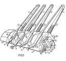
- Fig. 1 illustrates a dental appliance, which is provided with a valve arrangement according to the invention.
- the dental appliance comprises five blocks or assemblies 1-5, which are of uniform size and incorporated one with the other.
- Each of the blocks 1-4 is provided with an individual hand-operated instrument 6-9, whereas the block 5 may incorporate various types of control devices, these devices having no direct connection with the present invention.
- the blocks may vary in number, in accordance with the number of instruments provided.
- each instrument 6-9 is shown in an inoperative position, the instrument being located in a holder in a respective block 1-4.
- the holder has the form of a substantially V-shaped recess 10 in the inclined upper surface of the block.
- Each instrument 6-9 is connected to its respective block 1-4 through a pipe 11 incorporating channels for the flow of pressurized air, water and/or other media to the instrument, and optionally also a line for supplying electric current to said instrument.
- the pipe 11 may be of a kind known per se, and is conveniently provided with a tension spring 12 nearest respective blocks 1-4 and a flexible part nearest respective instruments 6-9.
- FIG. 1 The block 1 shown in Fig. 1 has been partially cut away, so as to illustrate the valve arrangement located therein.
- the valve arrangement 13 is shown more clearly in Figs. 2 and 3, each of which illustrates the block in cross-section, with the valve parts of the arrangement in their respective closed and open positions.
- Fig. 2 illustrates the valve arrangement 13 in its closed position.
- the valve arrangement of the Fig. 1 embodiment comprises three separate valves, and the cross-sectional view of Fig. 2 is taken through one of these valves.
- the valve illustrated in Fig. 2 includes a first valve part 14, a second valve part 15, and a flexible hose 16 joining the two valve parts 14 and 15.
- the first valve part 14 is connected firmly to a base part 17, which forms a stationary part of the block 1 and has incorporated therein three channels 18, 19 and 20 through which pressurized air, water and optionally other media can be passed from sources not shown.
- Fig. 1 illustrates the valve arrangement 13 in its closed position.
- the valve arrangement of the Fig. 1 embodiment comprises three separate valves, and the cross-sectional view of Fig. 2 is taken through one of these valves.
- the valve illustrated in Fig. 2 includes a first valve part 14, a second valve part 15, and a flexible hose 16 joining the two valve parts 14 and 15.
- the first valve part 14 is
- the first valve part 14 is provided with a channel 21, which is connected to the channel 19 and to the hose 16, the other end of which is connected to a channel 22 in the other valve part 15.
- the other valve part 15 is connected firmly to an intermediate member 23 which incorporates a channel 24, to which the channel 22 is connected.
- the channel 24 opens into a hose 25, which extends through the tension spring 12 and the pipe 11, and is connected to the instrument 6.
- the intermediate member 23, and therewith also the second valve part 15, is firmly mounted on an auxiliary component 26, which is pivotally connected to the base part 17 by a shaft or pivot pin 27.
- the auxiliary component 26 also carries the instrument holder 10 and the tension spring 12 of the pipe 11.
- the auxiliary component 26 also carries a switch 28, which through the action of a diaphragm 29 is actuated by the pressure in the . channel 24, to enable electric current to flow to the instrument in response to the pressure prevailing in the channel 24.
- an electric conductor extends from the switch 28 to the instrument. This electric conductor is shown in the drawing, but can obviously be located in the pipe 11.
- the hose 16 in this valve mode exhibits an abrupt fold or kink 30, which prevents the flow of medium through the hose 16 from the channel 21 in the first valve part, to the channel 22 in the second valve part 15.
- the auxiliary component 26 has swung anti-clockwise from the position illustrated in Fig. 2.
- This rotation of the auxiliary component takes place when the instrument or tool 6 is lifted from its holder 10 and moved to its working position, these actions causing the pipe 11 and the tension spring 12 thereof to be subjected to forces which cause the auxiliary component 26 to swing in the aforesaid manner.
- This swinging or rotary movement of the auxiliary component 26 is restricted through the agency of a bent end-part 31 which is located on a limiting device 32 extending outwardly from the auxiliary component 26 and which is brought into abutment with a projection 33 on the base part 17.
- the hose 16 forms the actual valve body for opening and closing the valve according to the invention, the valve being closed by bending the hose to form therein a sharp fold or kink 30.
- the valve is opened by straightening the hose 16 sufficiently to remove the fold 30.
- the movements between closed and open positions are effected under the influence of the forces occurring in the pipe 11 when the instrument concerned is lifted from its holder 10. Consequently, pressure medium will only flow to the instrument when it is lifted from its holder. In some cases, however, it may be desired to lift the instrument from its holder 10 without setting the instrument in function. This can be the case when changing or replacing instruments for example.
- the auxiliary component 26 is provided with a catch means 34, which can be placed manually behind the projection 33 on the base part 17 when the auxiliary component 26 occupies the position shown in Fig. 2, i.e. when the valve is closed.
Landscapes
- Health & Medical Sciences (AREA)
- Engineering & Computer Science (AREA)
- Public Health (AREA)
- Life Sciences & Earth Sciences (AREA)
- Animal Behavior & Ethology (AREA)
- General Health & Medical Sciences (AREA)
- Veterinary Medicine (AREA)
- General Engineering & Computer Science (AREA)
- Oral & Maxillofacial Surgery (AREA)
- Dentistry (AREA)
- Epidemiology (AREA)
- Water Supply & Treatment (AREA)
- Mechanical Engineering (AREA)
- Dental Tools And Instruments Or Auxiliary Dental Instruments (AREA)
- Multiple-Way Valves (AREA)
Description
- The invention relates to a valve arrangement for controlling the supply of pressurized-air, water and/or other media to at least one hand-operated tool, preferably an instrument for dental work, which valve arrangement includes for each tool a valve for each medium.
- Valve arrangements of this kind are known to the art, for example for use in appliances for dental work. Such appliances normally incorporate a plurality of mutually different tools or instruments, which are used singly, one at a time. Normally, each instrument requires to be supplied with air under pressure and/or water and possibly other media. All instruments are placed in a holder when not in use, and the holder is provided with means that ensures that only an instrument which has been removed from its holder can be set into operation.
- Such prior art appliances require an extremely large number of valves for controlling the flow of different media to the various instruments, therewith rendering the appliance complicated, expensive and bulky.
- The object of the present invention is to provide a valve arrangement of the aforesaid kind which is of simple construction and inexpensive to manufacture, and which is also reliable in use.
- This problem is solved by a valve arrangement as defined in claim 1.
- The invention will now be described with reference to the accompanying drawing, in which
- Fig. 1 is a partially cut-away perspective view of a dental appliance which incorporates a plurality of tools or instruments for dental work and which is equipped with a valve arrangement according to one embodiment of the invention;
- Fig. 2 is a cross-sectional view of the valve arrangement illustrated in Fig. 1, with the valve parts shown in their closed position; and
- Fig. 3 is a cross-sectional view similar to that of Fig. 2, but showing the valve parts in their open position.
- Fig. 1 illustrates a dental appliance, which is provided with a valve arrangement according to the invention. The dental appliance comprises five blocks or assemblies 1-5, which are of uniform size and incorporated one with the other. Each of the blocks 1-4 is provided with an individual hand-operated instrument 6-9, whereas the block 5 may incorporate various types of control devices, these devices having no direct connection with the present invention. As will be understood, the blocks may vary in number, in accordance with the number of instruments provided.
- In Fig. 1, each instrument 6-9 is shown in an inoperative position, the instrument being located in a holder in a respective block 1-4. In this embodiment, the holder has the form of a substantially V-
shaped recess 10 in the inclined upper surface of the block. Each instrument 6-9 is connected to its respective block 1-4 through apipe 11 incorporating channels for the flow of pressurized air, water and/or other media to the instrument, and optionally also a line for supplying electric current to said instrument. Thepipe 11 may be of a kind known per se, and is conveniently provided with atension spring 12 nearest respective blocks 1-4 and a flexible part nearest respective instruments 6-9. - The block 1 shown in Fig. 1 has been partially cut away, so as to illustrate the valve arrangement located therein. The
valve arrangement 13 is shown more clearly in Figs. 2 and 3, each of which illustrates the block in cross-section, with the valve parts of the arrangement in their respective closed and open positions. - Fig. 2 illustrates the
valve arrangement 13 in its closed position. The valve arrangement of the Fig. 1 embodiment comprises three separate valves, and the cross-sectional view of Fig. 2 is taken through one of these valves. The valve illustrated in Fig. 2 includes afirst valve part 14, asecond valve part 15, and aflexible hose 16 joining the twovalve parts first valve part 14 is connected firmly to abase part 17, which forms a stationary part of the block 1 and has incorporated therein threechannels first valve part 14 is provided with achannel 21, which is connected to thechannel 19 and to thehose 16, the other end of which is connected to achannel 22 in theother valve part 15. Theother valve part 15 is connected firmly to anintermediate member 23 which incorporates achannel 24, to which thechannel 22 is connected. In turn, thechannel 24 opens into ahose 25, which extends through thetension spring 12 and thepipe 11, and is connected to the instrument 6. - The
intermediate member 23, and therewith also thesecond valve part 15, is firmly mounted on anauxiliary component 26, which is pivotally connected to thebase part 17 by a shaft orpivot pin 27. Theauxiliary component 26 also carries theinstrument holder 10 and thetension spring 12 of thepipe 11. In the embodiment illustrated in Figs. 2 and 3, theauxiliary component 26 also carries aswitch 28, which through the action of adiaphragm 29 is actuated by the pressure in the .channel 24, to enable electric current to flow to the instrument in response to the pressure prevailing in thechannel 24. In this case, an electric conductor extends from theswitch 28 to the instrument. This electric conductor is shown in the drawing, but can obviously be located in thepipe 11. - As shown in Fig. 2, in which the
valve parts hose 16 in this valve mode exhibits an abrupt fold orkink 30, which prevents the flow of medium through thehose 16 from thechannel 21 in the first valve part, to thechannel 22 in thesecond valve part 15. - In the position illustrated in Fig. 3, the
auxiliary component 26 has swung anti-clockwise from the position illustrated in Fig. 2. This rotation of the auxiliary component takes place when the instrument or tool 6 is lifted from itsholder 10 and moved to its working position, these actions causing thepipe 11 and thetension spring 12 thereof to be subjected to forces which cause theauxiliary component 26 to swing in the aforesaid manner. This swinging or rotary movement of theauxiliary component 26 is restricted through the agency of a bent end-part 31 which is located on alimiting device 32 extending outwardly from theauxiliary component 26 and which is brought into abutment with aprojection 33 on thebase part 17. - When the
auxiliary component 26 is swung to the position illustrated in Fig. 3, the second valve part is moved away from thefirst valve part 14. This also causes the ends of thehose 16 to move away from one another, causing the hose to straighten to an extent such as to remove the fold orkink 30. Pressure medium can now flow from thechannel 19 through thechannel 21 and the nowopen hose 16, and also through thechannels hose 25, for the supply of medium to the instrument. Thus, when the valve arrangement occupies the position illustrated in Fig. 3, there is nothing to prevent the pressure medium from flowing therethrough, meaning that the valve comprising thevalve parts hose 16 is open. - As will be understood from the aforegoing, the
hose 16 forms the actual valve body for opening and closing the valve according to the invention, the valve being closed by bending the hose to form therein a sharp fold orkink 30. The valve is opened by straightening thehose 16 sufficiently to remove thefold 30. In the illustrated embodiment, the movements between closed and open positions are effected under the influence of the forces occurring in thepipe 11 when the instrument concerned is lifted from itsholder 10. Consequently, pressure medium will only flow to the instrument when it is lifted from its holder. In some cases, however, it may be desired to lift the instrument from itsholder 10 without setting the instrument in function. This can be the case when changing or replacing instruments for example. To this end, theauxiliary component 26 is provided with a catch means 34, which can be placed manually behind theprojection 33 on thebase part 17 when theauxiliary component 26 occupies the position shown in Fig. 2, i.e. when the valve is closed. - It will be understood that the invention is not restricted to the aforedescribed embodiment, and that modifications can be made thereto within the scope of the following claims.
Claims (5)
Priority Applications (3)
| Application Number | Priority Date | Filing Date | Title |
|---|---|---|---|
| EP86850149A EP0242494B1 (en) | 1986-04-23 | 1986-04-23 | A valve arrangement for controlling the supply of pressurized-air, water and/or other media to hand-operated tools, preferably instruments for dental work |
| DE8686850149T DE3663331D1 (en) | 1986-04-23 | 1986-04-23 | A valve arrangement for controlling the supply of pressurized-air, water and/or other media to hand-operated tools, preferably instruments for dental work |
| US07/191,026 US4863379A (en) | 1986-04-23 | 1988-04-28 | Valve arrangement for hand-operated dental tools |
Applications Claiming Priority (1)
| Application Number | Priority Date | Filing Date | Title |
|---|---|---|---|
| EP86850149A EP0242494B1 (en) | 1986-04-23 | 1986-04-23 | A valve arrangement for controlling the supply of pressurized-air, water and/or other media to hand-operated tools, preferably instruments for dental work |
Publications (2)
| Publication Number | Publication Date |
|---|---|
| EP0242494A1 EP0242494A1 (en) | 1987-10-28 |
| EP0242494B1 true EP0242494B1 (en) | 1989-05-17 |
Family
ID=8196517
Family Applications (1)
| Application Number | Title | Priority Date | Filing Date |
|---|---|---|---|
| EP86850149A Expired EP0242494B1 (en) | 1986-04-23 | 1986-04-23 | A valve arrangement for controlling the supply of pressurized-air, water and/or other media to hand-operated tools, preferably instruments for dental work |
Country Status (3)
| Country | Link |
|---|---|
| US (1) | US4863379A (en) |
| EP (1) | EP0242494B1 (en) |
| DE (1) | DE3663331D1 (en) |
Families Citing this family (8)
| Publication number | Priority date | Publication date | Assignee | Title |
|---|---|---|---|---|
| US6152735A (en) * | 1997-01-03 | 2000-11-28 | Meyer; Thomas C. | Whip arm mounting for dental delivery system control head |
| WO1998029051A1 (en) * | 1997-01-03 | 1998-07-09 | The Schein Dental Equipment Co. | Whip arm mounting for dental delivery system control head |
| GB9705657D0 (en) | 1997-03-19 | 1997-05-07 | Bacon Raymond J | Dispenser |
| SI2143458T1 (en) | 2002-03-22 | 2017-09-29 | Clinical Designs Limited | Can fixture |
| GB0304000D0 (en) * | 2003-02-21 | 2003-03-26 | Clinical Designs Ltd | Dispenser |
| GB0327112D0 (en) | 2003-11-21 | 2003-12-24 | Clincial Designs Ltd | Dispenser and reservoir |
| GB0328859D0 (en) | 2003-12-12 | 2004-01-14 | Clinical Designs Ltd | Dispenser and counter |
| EP3711737B1 (en) * | 2017-11-17 | 2023-06-07 | Takara Belmont Corporation | Instrument hose supporting device, and dental treatment apparatus having instrument hose supporting device |
Family Cites Families (10)
| Publication number | Priority date | Publication date | Assignee | Title |
|---|---|---|---|---|
| GB1012565A (en) * | 1962-06-13 | 1965-12-08 | Goddard & Sons Ltd J | Improvements in or relating to liquid flow control valves |
| DE2026839C3 (en) * | 1970-06-02 | 1974-05-09 | Siemens Ag, 1000 Berlin Und 8000 Muenchen | Holding and retraction device for hose and corded dental handpieces |
| US3959882A (en) * | 1974-06-17 | 1976-06-01 | Rackson Chester B | Fluid control apparatus |
| DE2443708A1 (en) * | 1974-09-12 | 1976-03-25 | Siemens Ag | DENTAL APPLIANCE |
| FR2458174A1 (en) * | 1979-05-29 | 1980-12-26 | Artus | PNEUMATIC DEVICE FOR CONTROLLING THE SPEED OF AN ELECTRIC MOTOR |
| DE2930853C2 (en) * | 1979-07-30 | 1986-10-02 | Siemens AG, 1000 Berlin und 8000 München | Dental handpiece with a valve for controlling the flow of a flowing medium |
| DK144993C (en) * | 1980-06-13 | 1982-12-20 | Flex Dental As | DENTAL DEVICE WITH NUMBER OF INSTRUMENTS CONNECTED TO A COMMON CONTROL CIRCUIT AND A COMMON OPERATING BODY |
| US4450862A (en) * | 1981-02-13 | 1984-05-29 | Syntex (U.S.A.) Inc. | Pinch valve assembly |
| US4375963A (en) * | 1981-06-25 | 1983-03-08 | Progressive Machine Products | Control unit for dental handpieces |
| DE3225794A1 (en) * | 1982-07-09 | 1984-01-12 | Kaltenbach & Voigt Gmbh & Co, 7950 Biberach | Dental instrument having a switching device intended for switching the flow of operating medium on and off |
-
1986
- 1986-04-23 DE DE8686850149T patent/DE3663331D1/en not_active Expired
- 1986-04-23 EP EP86850149A patent/EP0242494B1/en not_active Expired
-
1988
- 1988-04-28 US US07/191,026 patent/US4863379A/en not_active Expired - Fee Related
Also Published As
| Publication number | Publication date |
|---|---|
| DE3663331D1 (en) | 1989-06-22 |
| US4863379A (en) | 1989-09-05 |
| EP0242494A1 (en) | 1987-10-28 |
Similar Documents
| Publication | Publication Date | Title |
|---|---|---|
| EP0242494A1 (en) | A valve arrangement for controlling the supply of pressurized-air, water and/or other media to hand-operated tools, preferably instruments for dental work | |
| CA2183576A1 (en) | Self-closing dispensing valve | |
| TW354819B (en) | Fluid control apparatus having a cut-off release device | |
| EP0408865A3 (en) | Valve gun, in particular for high-pressure cleaning device | |
| SE441575B (en) | PNEUMATIC TOOL | |
| US4454768A (en) | Fluid flow controller | |
| US4614122A (en) | Fluid flow detector with adaptor | |
| CA2033581A1 (en) | Time-control circuit for pneumatically operable devices | |
| US4117861A (en) | Control and selector unit for dental handpieces | |
| EP1464448A2 (en) | Electric clamping apparatus with manual control | |
| US3994069A (en) | Dental installation | |
| GB1569031A (en) | Dental unit including fluid pressure-medium operated handpieces | |
| US4043041A (en) | Dental treatment control unit | |
| US3982322A (en) | Arrangement for the switching on-and-off of a pressurized medium flow | |
| US4502723A (en) | Oil hydraulic circuit for gripping device | |
| ATE403819T1 (en) | CONTROL VALVE FOR STEAM COOKER | |
| US3676931A (en) | Speed control for dental handpieces | |
| WO1996015374A1 (en) | Hydraulic pilot valve | |
| CA2248259A1 (en) | Diaphragm actuated air cycle valve | |
| ES2126455A1 (en) | Hand lever for pipe valves with detent mechanism | |
| WO2002029822A3 (en) | Portable programming system and control method therefor | |
| GB2173283A (en) | A valve | |
| TW428028B (en) | Swivel device with cantilever arm | |
| EP1026296A3 (en) | Air jet | |
| US4459106A (en) | Dental apparatus |
Legal Events
| Date | Code | Title | Description |
|---|---|---|---|
| PUAI | Public reference made under article 153(3) epc to a published international application that has entered the european phase |
Free format text: ORIGINAL CODE: 0009012 |
|
| 17P | Request for examination filed |
Effective date: 19870513 |
|
| AK | Designated contracting states |
Kind code of ref document: A1 Designated state(s): DE FR GB IT SE |
|
| 17Q | First examination report despatched |
Effective date: 19880217 |
|
| ITF | It: translation for a ep patent filed | ||
| GRAA | (expected) grant |
Free format text: ORIGINAL CODE: 0009210 |
|
| AK | Designated contracting states |
Kind code of ref document: B1 Designated state(s): DE FR GB IT SE |
|
| PG25 | Lapsed in a contracting state [announced via postgrant information from national office to epo] |
Ref country code: SE Effective date: 19890517 |
|
| REF | Corresponds to: |
Ref document number: 3663331 Country of ref document: DE Date of ref document: 19890622 |
|
| ET | Fr: translation filed | ||
| PLBE | No opposition filed within time limit |
Free format text: ORIGINAL CODE: 0009261 |
|
| STAA | Information on the status of an ep patent application or granted ep patent |
Free format text: STATUS: NO OPPOSITION FILED WITHIN TIME LIMIT |
|
| 26N | No opposition filed | ||
| ITTA | It: last paid annual fee | ||
| PGFP | Annual fee paid to national office [announced via postgrant information from national office to epo] |
Ref country code: GB Payment date: 19970418 Year of fee payment: 12 |
|
| PGFP | Annual fee paid to national office [announced via postgrant information from national office to epo] |
Ref country code: FR Payment date: 19970422 Year of fee payment: 12 |
|
| PG25 | Lapsed in a contracting state [announced via postgrant information from national office to epo] |
Ref country code: GB Free format text: LAPSE BECAUSE OF NON-PAYMENT OF DUE FEES Effective date: 19980423 |
|
| PG25 | Lapsed in a contracting state [announced via postgrant information from national office to epo] |
Ref country code: FR Free format text: THE PATENT HAS BEEN ANNULLED BY A DECISION OF A NATIONAL AUTHORITY Effective date: 19980430 |
|
| PGFP | Annual fee paid to national office [announced via postgrant information from national office to epo] |
Ref country code: DE Payment date: 19981029 Year of fee payment: 13 |
|
| GBPC | Gb: european patent ceased through non-payment of renewal fee |
Effective date: 19980423 |
|
| REG | Reference to a national code |
Ref country code: FR Ref legal event code: ST |
|
| PG25 | Lapsed in a contracting state [announced via postgrant information from national office to epo] |
Ref country code: DE Free format text: LAPSE BECAUSE OF NON-PAYMENT OF DUE FEES Effective date: 20000201 |
|
| PG25 | Lapsed in a contracting state [announced via postgrant information from national office to epo] |
Ref country code: IT Free format text: LAPSE BECAUSE OF NON-PAYMENT OF DUE FEES Effective date: 20050423 |