EP0242490B1 - Device and method for the introduction of samples to an apparatus - Google Patents
Device and method for the introduction of samples to an apparatus Download PDFInfo
- Publication number
- EP0242490B1 EP0242490B1 EP86810181A EP86810181A EP0242490B1 EP 0242490 B1 EP0242490 B1 EP 0242490B1 EP 86810181 A EP86810181 A EP 86810181A EP 86810181 A EP86810181 A EP 86810181A EP 0242490 B1 EP0242490 B1 EP 0242490B1
- Authority
- EP
- European Patent Office
- Prior art keywords
- container
- conveyor
- containers
- rollers
- grooves
- Prior art date
- Legal status (The legal status is an assumption and is not a legal conclusion. Google has not performed a legal analysis and makes no representation as to the accuracy of the status listed.)
- Expired - Lifetime
Links
Images


Classifications
-
- A—HUMAN NECESSITIES
- A24—TOBACCO; CIGARS; CIGARETTES; SIMULATED SMOKING DEVICES; SMOKERS' REQUISITES
- A24C—MACHINES FOR MAKING CIGARS OR CIGARETTES
- A24C5/00—Making cigarettes; Making tipping materials for, or attaching filters or mouthpieces to, cigars or cigarettes
- A24C5/32—Separating, ordering, counting or examining cigarettes; Regulating the feeding of tobacco according to rod or cigarette condition
- A24C5/34—Examining cigarettes or the rod, e.g. for regulating the feeding of tobacco; Removing defective cigarettes
Definitions
- the object of the invention is to create a simple construction device, operating in a perfectly reliable manner.
- the device designed as a function of this problem is capable of very diverse applications for selecting samples of all kinds and introducing them, for example, into an apparatus.
- the invention also relates to a control method using the device.
- Another object of the invention is an application of the device to solve a problem which arose in the feeding of a machine for controlling finished products, acting on filter sticks or cigarettes.
- This other object is a method of controlling a production of rod-shaped products using the device according to claim 1, characterized in that, in a production originating from several machines, samples of each compound are successively removed from each of the machines. of the same number of sticks, each sample is placed in one of the containers and the movements of the conveyor and of the emptying means are controlled so that all the sticks coming from a container have been removed from the receptacle when an emptying movement on the next container.
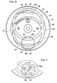
- FIG. 3 a perspective view showing a removable container
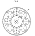
- fig. 6 is a partial elevation view showing the rear face of the transport disc.
- fig. 7 also a partial view in elevation showing the guide face of FIG. 5 during the rotation of the drive member.
- the rollers of the various plates 31 cooperate with the guide disc 13, the guide face 33 of which has a specially machined relief for this purpose and the outline of which is visible in FIG. 5.
- this face 33 of the support 13 which is limited at its periphery by a continuous rim 34, are milled two circular grooves 35 and 36 with rectangular profiles of the same width, the same depth and the same diameter and whose centers are offset l relative to each other along a vertical line extending diametrically across the face 33.
- the offset distance between the two grooves 35 and 36 corresponds to the spacing between two rollers 32 diametrically opposite of each of trays 31.
- the shaft 41 carries at its rear end a locating disc 45.
- This disc 45 plays a role similar to that of the member 23. While the detectors 25 and 26 cooperate with the disc 23, the disc 45 cooperates with a detector 46 which determines the moment when the motor 19 has driven the member 42 a full turn.
Abstract
Description
Dans la production des cigarettes, des filtres, et d'autres produits en forme de bâtonnets il est d'usage de soumettre ces produits à des tests en cours de fabrication. Lors de ces tests il est évidemment nécessaire que les échantillons provenant de la production des différentes machines, dans le cas ou plusieurs machines fonctionnent simultanément, soient traîtés de manière telle que l'enregistrement des résultats des tests soit constamment accompagné d'indications permettant de savoir de quelle machine proviennent les bâtonnets testés. Comme les tests se font très souvent de manière entièrement automatique et très rapidement, l'alimentation de la machine effectuant les tests pose un problème. Le but de la présente invention est donc de créer un dispositif automatique capable d'amener des groupes de produits en forme de bâtonnets sélectionnés dans la production de différentes machines dans un ordre prévisible, groupe par groupe, à un emplacement d'entrée de la machine de test, de manière que la corrélation entre la machine d'où provient l'échantillon et les résultats des tests puisse être maintenue facilement. De plus, le but de l'invention est de créer un dispositif de construction simple, fonctionnant de façon parfaitement fiable. D'autre part, on s'est aperçu que le dispositif conçu en fonction de ce problème était susceptible d'applications très diverses pour sélectionner des échantillons de toute nature et les introduire par exemple dans un appareil.In the production of cigarettes, filters, and other rod-shaped products it is customary to subject these products to tests during manufacture. During these tests it is obviously necessary that the samples coming from the production of the different machines, in the case where several machines operate simultaneously, are processed in such a way that the recording of the test results is constantly accompanied by indications allowing to know from which machine the rods tested come from. As the tests are very often done completely automatically and very quickly, the power supply to the machine carrying out the tests poses a problem. The object of the present invention is therefore to create an automatic device capable of bringing groups of rod-shaped products selected in the production of different machines in a predictable order, group by group, to a machine entry location. test, so that the correlation between the machine from which the sample comes and the test results can be easily maintained. In addition, the object of the invention is to create a simple construction device, operating in a perfectly reliable manner. On the other hand, it has been realized that the device designed as a function of this problem is capable of very diverse applications for selecting samples of all kinds and introducing them, for example, into an apparatus.
On connaît déjà des dispositifs de ce genre, notamment par les documents DE-A-2827192 et FR-A-2116232. Toutefois, ils ne sont pas conçus de manière à permettre un fonctionnement sélectif, c'est-à-dire à permettre par exemple de choisir à volonté l'ordre dans lequel certains groupes de produits sont amenés à la machine de test.Devices of this type are already known, in particular from documents DE-A-2827192 and FR-A-2116232. However, they are not designed to allow selective operation, that is to say to allow for example to choose at will the order in which certain groups of products are brought to the testing machine.
Ces dispositifs connus comportent des récipients conduits par un transporteur et se renversant un à un à un emplacemetn de décharge, sous l'effet de leur poids, de sorte que tous les récipients se renversent successivement et dans l'ordre de leur alignement sur le transporteur.These known devices include containers driven by a transporter and tipping one by one to a discharge location, under the effect of their weight, so that all the containers overturn successively and in the order of their alignment on the transporter. .
Le but de l'invention est donc de créer un dispositif qui offre des possibilités de commande plus diversifiées que celles des dispositifs connus et, de plus, dont la commande du renversement comporte un entraînement positif, au renversement et au redressement, indépendant du frottement ou de l'usure.The object of the invention is therefore to create a device which offers more diversified control possibilities than those of known devices and, moreover, the control of which reversal comprises a positive drive, for reversal and straightening, independent of friction or of wear.
L'invention concerne également un procédé de contrôle utilisant le dispositif.The invention also relates to a control method using the device.
Ainsi un premier objet de l'invention est un dispositif automatique d'introduction d'échantillons dans un appareil, comportant une série de récipients constitués d'éléments rigides présentant au moins un côté ouvert et montés sur un transporteur entraîné pas à pas de manière à amener les récipients un à un dans un emplacement de décharge, et des moyens de vidange d'un récipient qui se trouve à l'emplacement de décharge, par retournement de ce récipient de manière que son contenu tombe dans un réceptacle, le transporteur étant agencé de manière à déplacer les récipients en translation en maintenant l'ouverture du côté du haut, caractérisé en ce que les moyens de vidange comportent un ensemble d'entraînement en rotation monté à l'emplacement de décharge, et un moyen réalisant un accouplement coaxial entre le dit ensemble et un récipient se trouvant à l'emplacement de décharge.Thus, a first object of the invention is an automatic device for introducing samples into an apparatus, comprising a series of containers made up of rigid elements having at least one open side and mounted on a conveyor driven step by step so as to bringing the containers one by one to a discharge location, and means for emptying a container that is at the discharge location, by inverting this container so that its contents fall into a receptacle, the conveyor being arranged so as to move the containers in translation while maintaining the opening on the top side, characterized in that the emptying means comprise a rotational drive assembly mounted at the location discharge, and means providing a coaxial coupling between said assembly and a container located at the discharge location.
Un autre objet de l'invention est une application du dispositif pour résoudre un problème qui se posait dans l'alimentation d'une machine de contrôle de produits finis, agissant sur des bâtonnets de filtre ou des cigarettes. Cet autre objet est un procédé de contrôle d'une production de produits en forme de bâtonnets utilisant le dispositif selon la revendication 1, caractérisé en ce que, dans une production provenant de plusieurs machines, on retire successivement sur chacune des machines des échantillons composés chacun d'un même nombre de bâtonnets, on place chaque échantillon dans un des récipients et on commande les mouvements du transporteur et des moyens de vidange de manière que tous les bâtonnets provenant d'un récipient aient été extraits du réceptacle lorsque l'on commande un mouvement de vidange sur le récipient suivant.Another object of the invention is an application of the device to solve a problem which arose in the feeding of a machine for controlling finished products, acting on filter sticks or cigarettes. This other object is a method of controlling a production of rod-shaped products using the device according to
On va décrire ci-après à titre d'exemple une forme d'exécution de l'objet de l'invention et le déroulement d'une forme de mise en oeuvre du procédé.We will describe below by way of example an embodiment of the object of the invention and the course of a form of implementation of the method.
On se basera pour cela sur les dessins annexés, dont:We will base this on the accompanying drawings, including:
la fig. 1 est une vue en élévation frontale du dispositif d'introduction,fig. 1 is a front elevation view of the introduction device,
la fig. 2 une vue en élévation latérale,fig. 2 a side elevation view,
la fig. 3 une vue en perspective montrant un récipient amovible,fig. 3 a perspective view showing a removable container,
la fig. 4 une vue en coupe par la ligne IV-IV de la fig. 1 à plus grande échelle montrant le support de guidage et le disque transporteur,fig. 4 a sectional view through line IV-IV of FIG. 1 on a larger scale showing the guide support and the conveyor disc,
la fig. 5 est une vue en plan de la face frontale du support de guidage à la même échelle que la fig. 4,fig. 5 is a plan view of the front face of the guide support on the same scale as FIG. 4,
la fig. 6 est une vue en élévation partielle montrant la face arrière du disque de transport, etfig. 6 is a partial elevation view showing the rear face of the transport disc, and
la fig. 7 une vue également partielle et en élévation montrant la face de guidage de la fig. 5 au cours de la rotation de l'organe d'entraînement.fig. 7 also a partial view in elevation showing the guide face of FIG. 5 during the rotation of the drive member.
Le dispositif qui va être décrit représente une application particulière de l'invention. Il a été conçu comme un dispositif auxiliaire sur une alimentation de machine de contrôle déjà connue.The device which will be described represents a particular application of the invention. It was designed as an auxiliary device on an already known control machine supply.
Les fig. 1 et 2 montrent la disposition générale du dispositif et ses éléments principaux. Une embase 1 porte une trémie 2 munie à sa base d'un puits 3 dans lequel pénètre un moyen d'extraction 4. Ce moyen d'extraction comporte une paroi verticale 5 qui supporte et guide une bande souple d'entraînement 6 tendue sur deux rouleaux 7 et 8 qui sont mobiles en rotation aux deux extrémités de la paroi 5 et dont l'un est entraîné par un moteur (non représenté). La bande 6 porte des palettes rigides 9 qui sont fixées de distance en distance le long de la bande de manière à se placer obliquement par rapport à la paroi 5 lors du mouvement montant et lors du mouvement descendant de ces palettes. Comme on le voit, les palettes montantes sont situées de façon que leur bord supérieur soit à proxmité de la paroi avant du puits 3 de sorte que des bâtonnets 20, par exemple des cigarettes ou des bâtonnets de tabac ou des bâtonnets filtre placés dans la trémie s'accumulent dans le fond de cette dernière et entre la bande 6 et la paroi 3. Chaque palette 9 lors de son mouvement ascendant entraîne un bâtonnet, le fait passer par-dessus le rouleau 7 et le laisse ensuite tomber entre le moyen d'extraction 4 et la paroi arrière 10 du puits 3, chaque bâtonnet qui chute depuis le rouleau 7 parvenant dans une coulisse 11 dans laquelle il est bloqué et au moment voulu déplacé dans le sens axial afin de pénétrer dans un appareil de test (non représenté).Figs. 1 and 2 show the general arrangement of the device and its main elements. A
Au dessus de la trémie, le dispositif décrit comporte un appareillage d'alimentation dont les éléments principaux sont les suivants: un disque transporteur 12 de forme générale circulaire est porté par un axe central horizontal sur un support de guidage 13. Il peut être entraîné en rotation pas à pas à partir d'un moteur 14 (fig. 4) fixé au support de guidage 13. Dans sa face avant il porte une série de huit socles 15 de formes circulaires susceptibles d'être pourvu chacun d'un récipient 16 contenant des bâtonnets 20. Les socles 15 et les récipients 16 décrivent des mouvements de translation circulaire au cours de la rotation du disque 12. A la fig. 2, le support 13 est fermé à l'arrivée par un couvercle 50.Above the hopper, the device described comprises a supply apparatus, the main elements of which are as follows: a
Un des récipients 16 est représenté à la fig. 3. Il s'agit d'une pièce rigide de forme cylindrique qui peut être avantageusement en matière plastique transparente dont la partie arrière 17 forme un élément d'engagement cylindrique capable d'être mis en place par engagement à force sur les socles 15. La partie avant du récipient 16 a la forme d'un bac, la surface cylindrique du récipient étant coupée en 18 sur une partie de sa largeur de façon à former une ouverture latérale. On peut placer dans le récipient 16 un certain nombre de bâtonnets formant un échantillon prélevé sur une des machines de production. Cet échantillon comprendra par exemple cinq bâtonnets. Les récipients 16 pourraient être fixés à demeure sur les socles 15, le personnel qui sélectionne les échantillons ayant alors à placer chaque échantillon dans un des récipients au moment où il atteint une certaine position de charge, mais on peut également prévoir que les récipients sont amovibles de sorte que le personnel qui sélectionne les bâtonnets peut effectuer le remplissage de chaque récipient directement auprès de la machine dont l'échantillon est soutiré. Comme on le voit à la fig. 1, les récipients sont fixés chacun aux différents socles de façon que les ouvertures 18 soient situées à la partie supérieure du récipient et le disque transporteur 12 est entraîné en rotation pas à pas par exemple dans le sens de la flèche A à la fig. 1, de façon qu'à chaque pas un des récipients parvienne dans une position inférieure qui est une position de décharge située immédiatement sous l'axe du disque. Lorsque tous les bâtonnets 20 provenant d'un récipient ont été éliminés de la trémie 2 par les moyens d'extraction 4, alors le récipient suivant qui est parvenu entretemps dans la position de décharge, est entraîné en rotation d'un tour complet, de sorte que les bâtonnets se déchargent dans la trémie par gravité. Il suffit donc de compter les bâttonets qui sont extraits un à un de la trémie puis amenés à l'entrée de la machine de test et de comparer le nombre de bâtonnets comptés avec le nombre de bâtonnets par échantillon pour pouvoir repérer à quel moment la machine de test doit passer d'un échantillon provenant d'une machine de production à un autre échantillon provenant d'une autre machine de production. Cette comparaison permet de commander l'avance du transporteur.One of the
Les fig. 4 à 6 montrent comment le disque transporteur 12 peut être actionné dans des conditions telles que les socles 15 décrivent des mouvements de translations circulaires et comment le socle 15 qui parvient dans la position de décharge peut être automatiquement accouplé à un moteur de décharge 19 de façon que lorsque celui-ci est actionné le socle correspondant effectue un mouvement de rotation complet autour de son axe et par conséquent vide le récipient dans la trémie. Le disque 12 est porté par un arbre 21 qui est supporté par des paliers 22 au centre du support de guidage 13. Ce dernier est une pièce fixe de forme circulaire, supportée sur l'embase 1. Un disque de repérage 23 d'une pièce avec un arbre 24 est fixé à l'extrémité arrière de l'arbre 21, de sorte que, comme on le verra plus loin encore, des détecteurs 25 et 26 peuvent commander les mouvements de rotation pas à pas du disque 12 et les diverses opérations d'un cycle complet de testage des bâtonnets.Figs. 4 to 6 show how the
Le moteur 14 entraîne par son pignon 27 une couronne dentée à denture intérieure 28 fixée dans une creusure centrale du disque 12. D'autre part, chacun des huits socles 15 est solidaire d'un élément d'arbre 29 et est supporté par des paliers 30 dans une ouverture du disque 12. A son extrémité opposée au socle 15, chaque arbre 29 porte un plateau circulaire 31 qui est noyé dans une plage élargie de lacreusure du disque 12 moins profonde que sa partie centrale. Chaque plateau 31 est muni de quatre galets 32 répartis à 90° les uns des autres sur le pourtour du plateau et faisant saillie vers l'arrière deux de ces galets s'étendant à une distance du plateau 31 plus grande que les deux autres. Ainsi, les quatre galets sont répartis par paires homologues, les deux galets de chaque paire étant à la même distance du plateau et étant diamétralement opposés.The
Les galets des différents plateaux 31 coopèrent avec le disque de guidage 13 dont la face de guidage 33 présente dans ce but un relief usiné spécialement et dont le tracé est visible à la fig. 5. Dans cette face 33 du support 13 qui est limitée à sa périphérie par un rebord continu 34, sont fraisées deux gorges circulaires 35 et 36 à profils rectangulaires de même largeur, de même profondeur et de même diamètre et dont les centres sont décalés l'un par rapport à l'autre le long d'une ligne verticale s'étendant diamétralement à travers la face 33. La distance de décalage entre les deux gorges 35 et 36 correspond à l'écartement entre deux galets 32 diamétralement opposés de chacun des plateaux 31. Ainsi à la fig. 5 on a représenté en traits mixtes les quatre galets 32 d'un plateau 31 qui se trouve en position supérieure et on peut imaginer facilement que si le disque 12 est entraîné en rotation autour de son axe monté dans les paliers 26, les deux galets 32 qui sont engagés dans les gorges 35 et 36 vont être forcés de se déplacer en restant placés sur une même ligne verticale.The rollers of the
Pour assurer ce mouvement de translation circulaire sans risque de coincement et de bloquage, la face de guidage 33 du support 13 comporte encore quatre rampes saillantes 37 dont deux (37a) sont prévues aux points de croisement des deux gorges 35 et 36 à l'extérieur de ces gorges et les deux autres (37b et c) respectivement au point supérieur de la gorge 35 et au point inférieur de la gorge 36, à l'intérieur de ces gorges. Chaque rampe 37 est limitée par trois arcs de cercles qui limitent également soit l'une des gorges 35 ou 36, soit en partie chacune de ces deux gorges. On voit que les galets 32 qui sont situés sur le diamètre horizontal du plateau 31 sont guidés dans la position supérieure ou ils sont visibles à la fig. 5 par deux portions de rampes incurvées 48 et 49 du plot saillant 37b. Il en sera de même en ce qui concerne le plot saillant 37c situé à la partie inférieure du réseau de gorges et de rampes représenté à la fig. 5. Ce réseau force donc les plateaux 31 et par conséquent les socles 15 à effectuer un mouvement de translation circulaire lorsque le disque 12 est entraîné en rotation par le moteur 14.To ensure this circular translation movement without risk of jamming and blocking, the
Ainsi l'ouverture 18 des récipients 16 est constamment maintenue à la partie supérieure des récipients. Deux des galets 32 de chacun des plateaux 31 sont engagés dans les gorges 35 et 36 et restent situés sur un diamètre vertical tout au long de la rotation du disque 12. Les deux autres galets 32 coopèrent avec les rampes 37a, b, c alternativement avec leur surface incurvée interne et leur surface incurvée externe dans les quatre orientations haut, bas, droite, gauche.Thus the
On va décrire plus en détail l'agencement de la partie du support 13 qui est située en dessous de l'axe de ce support. Un logement cylindrique 38 dont le fond est percé d'une ouverture 39 équipée de paliers 40, est ménagé dans cette partie du support 13. Un organe d'entraînement comportant un arbre 41 est supporté par des paliers 40 tandis qu'un disque 42 solidaire de l'arbre 41 est noyé dans le logement 38. L'organe d'entraînement comporte encore une roue dentée 43 (fig. 5) qui est en prise avec un pignon 44 solidiare de l'arbre du moteur 19.We will describe in more detail the arrangement of the part of the
Une face frontale 45 du disque d'entraînement 42 s'étend à fleur de la surface de guidage 33 du support 13 et présente un relief formé de deux portions 35a et 36a de gorges ayant les mêmes dimensions que les gorges 35 et 36. Normalement, ces portions de gorge 35a et 36a de l'organe d'entraînement se trouvent exactement dans le prolongement des gorges 35 et 36, de sorte que la partie proéminente qui forme la rampe 37c est également solidaire du disque 42. On constate donc que si le disque d'entraînement 42 a la position représentée à la fig. 5, son relief se confond avec celui des gorges 35 et 36. Lors de la rotation pas à pas du disque 12 les plateaux 31 vont s'engager successivement dans les segments de gorges 35a et 36a pour parvenir par la position inférieure qui a été désignée plus haut comme position de décharge. Le socle correspondant sera orienté de façon que l'ouverture du récipient fixé à ce socle sera dirigée vers le haut. Si à ce moment le moteur 19 est enclenché de façon telle que la roue dentée 43 effectue un tour complet sur elle-même, les segments de gorge 35a, 36a et la rampe 37c coopèrent avec les galets 32 à la manière d'un accouplement comme on le voit à la fig. 7. La rotation de l'organe d'entraînement 41, 42, 43 entraîne celle du plateau 31 et du socle 15 qui se trouvent en position de décharge. On notera que cet accouplement automatique s'effectue d'une part sans aucune commande électrique et d'autre part en corrigeant automatiquement des erreurs de centrage éventuelles. Un des grands avantages de la disposition décrite est précisément due au fait que l'organe d'entraînement 41, 42, 43 permet de faire tourner sur lui-même le récipient qui se trouve en position de dêcharge, même si l'arrêt du dis-que 12 n'a pas êtê commandê par une precision telle qu'un socle 15 se trouve rigoureusement sur le diamêtre vertical passant par le centre du support de guidage 13.A
Revenant à la fig. 4, on voit encore que l'arbre 41 porte à son extrémité arrière un disque 45 de repêrage. Ce disque 45 joue un rôle analogue à celui de l'organe 23. Alors que les détecteurs 25 et 26 coopèrent avec le disque 23, le disque 45 coopère avec un détecteur 46 qui détermine le moment où le moteur 19 a entraîné l'organe 42 d'un tour complet.Returning to fig. 4, it can also be seen that the
Le détecteur 25 coopère avec des Eentes radiales 47 pratiquées sur la périphérie du disque 23 et commande l'avance pas à pas du disque 12. Le détecteur 26 détecte le point zéro de départ du cycle. D'autres détecteurs peuvent encore être prévus, qui détectent la présence de composants d'un échantillon dans le réceptacle et/ou dans les récipients, ainsi que des compteurs.The
On peut ainsi établir des programmes de fonctionnement différents en choisissant à volonté certains critères de fonctionnement, par exemple action de retournement sur des récipients se trouvant dans différentes positions, timing des opérations, ordre des opérations de vidange, entraînement vers la position de décharge par le chemin le plus court, etc.It is thus possible to establish different operating programs by choosing at will certain operating criteria, for example turning action on containers located in different positions, timing of operations, order of emptying operations, drive to the discharge position by the shortest path, etc.
Le principe du dispositif décrit est que les mêmes moyens qui assurent une translation circulaire des socles des plateaux assurent sur chaque plateau qui se trouve dans une position de décharge, l'accouplement de ce plateau avec le moteur de décharge.The principle of the device described is that the same means which ensure a circular translation of the bases of the plates ensure on each plate which is in a discharge position, the coupling of this plate with the discharge motor.
Bien qu'on ait décrit ici un système dans lequel la face de guidage du support de guidage comporte deux gorges circulaires profondes et à quatre endroits de ce réseau de gorges quatre saillies en forme de croissants de lune permet d'entraîner huit socles en les maintenant d'une façon suffisamment sûre pour éviter tout arrêt et tout coincement. Dans une autre forme d'exécution on pourrait imaginer d'autres réseaux de gorges et dans certains cas il pourrait ne pas être indispensable de prévoir quatre galets un revers de chaque plateau solidaire d'un socle. Toutefois, l'exécution représentée au dessin est celle qui a permis de vérifier de la manière la plus sûre possible le bon fonctionnement de l'entraînement et du guidage. Dans une autre forme d'exécution, les socles pourraient ne pas être guidés par les gorges 35 et 36 sur toute la longueur de leur trajectoire. En particulier les socles pourraient être montés sur des chaînes décrivant un chemin non circulaire tout en décrivant un mouvement de translation au cours duquel ils conservent une orientation parallèle à eux-mêmes.Although a system has been described here in which the guide face of the guide support has two deep circular grooves and at four places in this network of grooves four projections in the form of crescent moons allow eight bases to be held while maintaining them sufficiently safe to avoid all stopping and all jamming. In another embodiment one could imagine other networks of grooves and in some cases it might not be essential to provide four rollers with a back of each plate secured to a base. However, the execution shown in the drawing is that which made it possible to verify as safely as possible the proper functioning of the drive and of the guidance. In another embodiment, the bases may not be guided by the
Dans d'autres formes d'exécution encore on pourrait compter, sélectionner ou distribuer des échantillons d'autre nature que des groupes de bâtonnets par exemple des doses de poudre ou de granulés, le cas échéant des liquides, des pièces, etc.In still other embodiments, samples of other kinds than groups of sticks could be counted, selected or distributed, for example doses of powder or granules, if necessary liquids, parts, etc.
Claims (10)
- An automatic device for introducing samples into an apparatus, comprising a series of containers (16) made up of rigid elements having at least one open side (18) and mounted on a conveyor (12) driven step by step so as to bring the containers (16) one by one to a discharge location, and means for emptying (19, 42) a container which is at a discharge location by turning the container over so that its contents fall into a receptacle (2), the container (12) being arranged so as to move the containers (16) in translation while maintaining the opening (18) toward the top, characterized in that the emptying means comprise a rotating drive assembly (19, 42) which is integral with the said conveyor (12) and mounted at the discharge location and means (32, 35a) of achieving a coaxial coupling between the said assembly and a container (16) situated at the discharge location.
- A device according to claim 1, characterized in that the containers (16) are fixed removably on the conveyor (12).
- A device according to claim 1, characterized in that the conveyor (12), mounted on a guide support (13), bears a series of rotary pedestals (15) having parallel axes of rotation, the containers (16) being fixed to the pedestals, guided in circular translation during the movement of the conveyor, and coupling in the discharge location to a drive means (42) which is part of the said assembly (19, 42).
- A device according to claim 3, characterized in that the conveyor (12) comprises a disc mounted rotatively around a horizontal axis (21), the axes of rotation (29) of the pedestals (15) being also horizontal.
- A device according to claim 4, characterized in that the pedestals (15) are equipped with rollers (32) distributed about their axis (29), and in that the guide support (13) comprises a guide face (33) parallel to the conveyor disc (12) and, in this face, a network of grooves (35, 36) and ramps (37) with which the rollers (32) cooperate during the movement of the conveyor (12) to impart to the pedestals (15) a translatory movement along an endless path.
- A device according to claim 5, characterized in that the guide support (13) bears the said drive member (42) coupled to a discharge motor (19), this drive member having a front face (45) situated in the prolongation of the guide face (33) and having portions of grooves (35a) and ramps (37) capable, at the time of rotation of the drive member (42), of transmitting to the rollers (32) belonging to a pedestal (15) situated in the discharge location the movement of rotation which is imparted by the discharge motor (19) to the drive member.
- A device according to claim 1, characterized in that it further comprises an assembly of control means (25, 26, 47, 45, 46) capable of controlling, on the one hand, step-by-step movements of the conveyor (12) and, on the other hand, after each step, the actuation of the emptying means (19, 42) acting upon the container situated in the discharge location.
- A device according to claim 7, characterized in that the discharge location is at the lowest point of the path described by the pedestals (15).
- A device according to claim 7, characterized in that the control assembly comprises detectors of the presence of components of a sample in the container (2), and/or in the containers (16), as well as counters.
- A process for checking an output of rod-shaped products using the device according to claim 1, characterized in that, in an output coming from several machines, samples each composed of the same number of rods (20) are successively withdrawn from each of the machines, each sample is placed in one of the containers (16) and the movements of the conveyor (12) and of the emptying means (19, 42) are controlled so that all the rods coming from a container have been extracted from the container (2) when an emptying movement is executed on the following container.
Priority Applications (3)
| Application Number | Priority Date | Filing Date | Title |
|---|---|---|---|
| AT86810181T ATE61112T1 (en) | 1986-04-18 | 1986-04-18 | DEVICE AND METHOD FOR INTRODUCING SAMPLES INTO A FACILITY. |
| EP86810181A EP0242490B1 (en) | 1986-04-18 | 1986-04-18 | Device and method for the introduction of samples to an apparatus |
| DE8686810181T DE3677768D1 (en) | 1986-04-18 | 1986-04-18 | DEVICE AND METHOD FOR THE INTRODUCTION OF SAMPLES INTO A DEVICE. |
Applications Claiming Priority (1)
| Application Number | Priority Date | Filing Date | Title |
|---|---|---|---|
| EP86810181A EP0242490B1 (en) | 1986-04-18 | 1986-04-18 | Device and method for the introduction of samples to an apparatus |
Publications (2)
| Publication Number | Publication Date |
|---|---|
| EP0242490A1 EP0242490A1 (en) | 1987-10-28 |
| EP0242490B1 true EP0242490B1 (en) | 1991-02-27 |
Family
ID=8196460
Family Applications (1)
| Application Number | Title | Priority Date | Filing Date |
|---|---|---|---|
| EP86810181A Expired - Lifetime EP0242490B1 (en) | 1986-04-18 | 1986-04-18 | Device and method for the introduction of samples to an apparatus |
Country Status (3)
| Country | Link |
|---|---|
| EP (1) | EP0242490B1 (en) |
| AT (1) | ATE61112T1 (en) |
| DE (1) | DE3677768D1 (en) |
Families Citing this family (2)
| Publication number | Priority date | Publication date | Assignee | Title |
|---|---|---|---|---|
| CN110924081B (en) * | 2018-09-19 | 2023-04-07 | 青岛海高设计制造有限公司 | Quantitative distribution mechanism of washing machine and washing machine |
| CN110697317B (en) * | 2019-10-15 | 2021-08-10 | 湖南雪峰食品发展有限公司 | Canned fruit ejection of compact pipeline safety precaution device |
Family Cites Families (7)
| Publication number | Priority date | Publication date | Assignee | Title |
|---|---|---|---|---|
| US2745410A (en) * | 1953-11-02 | 1956-05-15 | Molins Machine Co Ltd | Delivery of cigarettes to a cigarettepacking machine |
| US3258117A (en) * | 1963-08-27 | 1966-06-28 | Brown & Williamson Tobacco | Automatic means for testing and assorting cigarettes according to porosity |
| GB1278597A (en) * | 1968-07-16 | 1972-06-21 | Molins Machine Co Ltd | Improvements in data-processing system |
| FR2116232B1 (en) * | 1970-11-13 | 1974-07-12 | Vaughn Gregor | |
| ZA751761B (en) * | 1974-04-05 | 1976-02-25 | Ligett & Myers Inc | Apparatus and method for sorting cigarettes |
| DE2827192A1 (en) * | 1978-06-21 | 1980-01-10 | Alfred Dr Monerjan | Automatic analyser with increased load capacity transport section - has additional drive chain housing with meandering chain guide within additional section |
| DE3311544C1 (en) * | 1983-03-30 | 1988-08-18 | Hans Holger Wiese GmbH & Co KG, 3006 Burgwedel | Pendulum-suspended cup with control curve for a cup conveyor |
-
1986
- 1986-04-18 EP EP86810181A patent/EP0242490B1/en not_active Expired - Lifetime
- 1986-04-18 AT AT86810181T patent/ATE61112T1/en not_active IP Right Cessation
- 1986-04-18 DE DE8686810181T patent/DE3677768D1/en not_active Expired - Fee Related
Also Published As
| Publication number | Publication date |
|---|---|
| DE3677768D1 (en) | 1991-04-04 |
| EP0242490A1 (en) | 1987-10-28 |
| ATE61112T1 (en) | 1991-03-15 |
Similar Documents
| Publication | Publication Date | Title |
|---|---|---|
| CA1200425A (en) | Skewering device for meats and other edibles | |
| EP2821146B1 (en) | Shaking and centrifugation device and method | |
| EP2066261B2 (en) | Machine for filling artificial insemination straws with semen | |
| WO2011015528A2 (en) | Device and method for dispensing a material into a petri dish | |
| EP1693317B1 (en) | Automatic dispensing machine for products | |
| EP0472457B1 (en) | Purging and flushing apparatus for disposable bottles containing a toxic product | |
| EP3491394B1 (en) | Device for shaking and sampling biological liquids | |
| FR2754599A1 (en) | AUTOMATIC IMMUNOLOGICAL ASSAY APPARATUS | |
| EP0242490B1 (en) | Device and method for the introduction of samples to an apparatus | |
| EP1077891B1 (en) | Mechanism for automatically directing and dispensing parts | |
| FR2574252A1 (en) | Installation for the automated manufacture of kebabs | |
| EP1089850B1 (en) | Device for supplying to a machine-tool bars to be machined | |
| WO1988005541A1 (en) | Apparatus for dispensing means into receptacles arranged in groups on plates | |
| EP2896584B1 (en) | Facility for monitoring the quality of a series of items, in particular of bottles | |
| EP1541276B1 (en) | Device for automatically taking / bringing back a tool from / to a pile of tools | |
| EP0322269A1 (en) | Automatic sachet dispenser | |
| EP0023941A1 (en) | Method and device for moulding curd in making blocks of cheese | |
| WO1998041100A1 (en) | Machine for the automatic production of meat or vegetable brochettes spitted on wooden picks in particular | |
| FR2574753A1 (en) | METHOD AND MACHINE FOR FILLING AND STOPPING BOTTLES | |
| WO1992008359A1 (en) | Machine for preparing kebabs | |
| EP0192571B1 (en) | Test tubes support for a centrifuge, and its manufacturing method | |
| BE879828R (en) | APPARATUS FOR AUTOMATICALLY CANNING CYLINDRICAL OBJECTS AND A BOX, PARTICULARLY FOR SUCH AN APPARATUS | |
| FR2586232A1 (en) | Dispenser of products stored in loose form, and in particular pieces of sugar | |
| FR2591511A1 (en) | DEVICE FOR THE AUTOMATIC STORAGE OF SIMILAR SHAPE BODIES | |
| FR2774863A1 (en) | Manufacture of filled pancake purses |
Legal Events
| Date | Code | Title | Description |
|---|---|---|---|
| PUAI | Public reference made under article 153(3) epc to a published international application that has entered the european phase |
Free format text: ORIGINAL CODE: 0009012 |
|
| AK | Designated contracting states |
Kind code of ref document: A1 Designated state(s): AT BE CH DE FR GB IT LI LU NL SE |
|
| 17P | Request for examination filed |
Effective date: 19871231 |
|
| 17Q | First examination report despatched |
Effective date: 19890615 |
|
| GRAA | (expected) grant |
Free format text: ORIGINAL CODE: 0009210 |
|
| AK | Designated contracting states |
Kind code of ref document: B1 Designated state(s): AT BE CH DE FR GB IT LI LU NL SE |
|
| PG25 | Lapsed in a contracting state [announced via postgrant information from national office to epo] |
Ref country code: SE Effective date: 19910227 Ref country code: AT Effective date: 19910227 |
|
| REF | Corresponds to: |
Ref document number: 61112 Country of ref document: AT Date of ref document: 19910315 Kind code of ref document: T |
|
| REF | Corresponds to: |
Ref document number: 3677768 Country of ref document: DE Date of ref document: 19910404 |
|
| ITF | It: translation for a ep patent filed |
Owner name: STUDIO TORTA SOCIETA' SEMPLICE |
|
| PG25 | Lapsed in a contracting state [announced via postgrant information from national office to epo] |
Ref country code: LU Free format text: LAPSE BECAUSE OF NON-PAYMENT OF DUE FEES Effective date: 19910430 |
|
| GBT | Gb: translation of ep patent filed (gb section 77(6)(a)/1977) | ||
| PLBE | No opposition filed within time limit |
Free format text: ORIGINAL CODE: 0009261 |
|
| STAA | Information on the status of an ep patent application or granted ep patent |
Free format text: STATUS: NO OPPOSITION FILED WITHIN TIME LIMIT |
|
| 26N | No opposition filed | ||
| PGFP | Annual fee paid to national office [announced via postgrant information from national office to epo] |
Ref country code: FR Payment date: 19960311 Year of fee payment: 11 |
|
| PGFP | Annual fee paid to national office [announced via postgrant information from national office to epo] |
Ref country code: BE Payment date: 19960318 Year of fee payment: 11 |
|
| PGFP | Annual fee paid to national office [announced via postgrant information from national office to epo] |
Ref country code: GB Payment date: 19960319 Year of fee payment: 11 |
|
| PGFP | Annual fee paid to national office [announced via postgrant information from national office to epo] |
Ref country code: NL Payment date: 19960322 Year of fee payment: 11 |
|
| PGFP | Annual fee paid to national office [announced via postgrant information from national office to epo] |
Ref country code: DE Payment date: 19960325 Year of fee payment: 11 |
|
| PGFP | Annual fee paid to national office [announced via postgrant information from national office to epo] |
Ref country code: CH Payment date: 19960402 Year of fee payment: 11 |
|
| PG25 | Lapsed in a contracting state [announced via postgrant information from national office to epo] |
Ref country code: GB Effective date: 19970418 |
|
| PG25 | Lapsed in a contracting state [announced via postgrant information from national office to epo] |
Ref country code: LI Free format text: LAPSE BECAUSE OF NON-PAYMENT OF DUE FEES Effective date: 19970430 Ref country code: CH Free format text: LAPSE BECAUSE OF NON-PAYMENT OF DUE FEES Effective date: 19970430 Ref country code: BE Effective date: 19970430 |
|
| BERE | Be: lapsed |
Owner name: S.A. FABRIQUES DE TABAC REUNIES Effective date: 19970430 |
|
| PG25 | Lapsed in a contracting state [announced via postgrant information from national office to epo] |
Ref country code: NL Effective date: 19971101 |
|
| GBPC | Gb: european patent ceased through non-payment of renewal fee |
Effective date: 19970418 |
|
| REG | Reference to a national code |
Ref country code: CH Ref legal event code: PL |
|
| PG25 | Lapsed in a contracting state [announced via postgrant information from national office to epo] |
Ref country code: FR Free format text: LAPSE BECAUSE OF NON-PAYMENT OF DUE FEES Effective date: 19971231 |
|
| PG25 | Lapsed in a contracting state [announced via postgrant information from national office to epo] |
Ref country code: DE Free format text: LAPSE BECAUSE OF NON-PAYMENT OF DUE FEES Effective date: 19980101 |
|
| NLV4 | Nl: lapsed or anulled due to non-payment of the annual fee |
Effective date: 19971101 |
|
| REG | Reference to a national code |
Ref country code: FR Ref legal event code: ST |
|
| PG25 | Lapsed in a contracting state [announced via postgrant information from national office to epo] |
Ref country code: IT Free format text: LAPSE BECAUSE OF NON-PAYMENT OF DUE FEES;WARNING: LAPSES OF ITALIAN PATENTS WITH EFFECTIVE DATE BEFORE 2007 MAY HAVE OCCURRED AT ANY TIME BEFORE 2007. THE CORRECT EFFECTIVE DATE MAY BE DIFFERENT FROM THE ONE RECORDED. Effective date: 20050418 |