EP0241820A2 - Injected part take-out device for injection-moulding machines - Google Patents
Injected part take-out device for injection-moulding machines Download PDFInfo
- Publication number
- EP0241820A2 EP0241820A2 EP87104955A EP87104955A EP0241820A2 EP 0241820 A2 EP0241820 A2 EP 0241820A2 EP 87104955 A EP87104955 A EP 87104955A EP 87104955 A EP87104955 A EP 87104955A EP 0241820 A2 EP0241820 A2 EP 0241820A2
- Authority
- EP
- European Patent Office
- Prior art keywords
- drive
- support
- link
- injection molding
- slide
- Prior art date
- Legal status (The legal status is an assumption and is not a legal conclusion. Google has not performed a legal analysis and makes no representation as to the accuracy of the status listed.)
- Withdrawn
Links
- 238000001746 injection moulding Methods 0.000 title claims abstract description 29
- 239000000725 suspension Substances 0.000 claims abstract description 20
- 230000005540 biological transmission Effects 0.000 claims description 14
- 238000002347 injection Methods 0.000 claims description 7
- 239000007924 injection Substances 0.000 claims description 7
- 230000001360 synchronised effect Effects 0.000 claims description 2
- 238000010276 construction Methods 0.000 abstract description 2
- 238000000465 moulding Methods 0.000 description 3
- 239000004952 Polyamide Substances 0.000 description 2
- 229920002647 polyamide Polymers 0.000 description 2
- 238000006073 displacement reaction Methods 0.000 description 1
- 230000000694 effects Effects 0.000 description 1
- 238000009434 installation Methods 0.000 description 1
- 239000004033 plastic Substances 0.000 description 1
Images
Classifications
-
- B—PERFORMING OPERATIONS; TRANSPORTING
- B29—WORKING OF PLASTICS; WORKING OF SUBSTANCES IN A PLASTIC STATE IN GENERAL
- B29C—SHAPING OR JOINING OF PLASTICS; SHAPING OF MATERIAL IN A PLASTIC STATE, NOT OTHERWISE PROVIDED FOR; AFTER-TREATMENT OF THE SHAPED PRODUCTS, e.g. REPAIRING
- B29C45/00—Injection moulding, i.e. forcing the required volume of moulding material through a nozzle into a closed mould; Apparatus therefor
- B29C45/17—Component parts, details or accessories; Auxiliary operations
- B29C45/40—Removing or ejecting moulded articles
- B29C45/42—Removing or ejecting moulded articles using means movable from outside the mould between mould parts, e.g. robots
-
- B—PERFORMING OPERATIONS; TRANSPORTING
- B25—HAND TOOLS; PORTABLE POWER-DRIVEN TOOLS; MANIPULATORS
- B25J—MANIPULATORS; CHAMBERS PROVIDED WITH MANIPULATION DEVICES
- B25J9/00—Programme-controlled manipulators
- B25J9/0009—Constructional details, e.g. manipulator supports, bases
- B25J9/0012—Constructional details, e.g. manipulator supports, bases making use of synthetic construction materials, e.g. plastics, composites
-
- B—PERFORMING OPERATIONS; TRANSPORTING
- B25—HAND TOOLS; PORTABLE POWER-DRIVEN TOOLS; MANIPULATORS
- B25J—MANIPULATORS; CHAMBERS PROVIDED WITH MANIPULATION DEVICES
- B25J9/00—Programme-controlled manipulators
- B25J9/02—Programme-controlled manipulators characterised by movement of the arms, e.g. cartesian coordinate type
- B25J9/023—Cartesian coordinate type
-
- B—PERFORMING OPERATIONS; TRANSPORTING
- B29—WORKING OF PLASTICS; WORKING OF SUBSTANCES IN A PLASTIC STATE IN GENERAL
- B29C—SHAPING OR JOINING OF PLASTICS; SHAPING OF MATERIAL IN A PLASTIC STATE, NOT OTHERWISE PROVIDED FOR; AFTER-TREATMENT OF THE SHAPED PRODUCTS, e.g. REPAIRING
- B29C45/00—Injection moulding, i.e. forcing the required volume of moulding material through a nozzle into a closed mould; Apparatus therefor
- B29C45/17—Component parts, details or accessories; Auxiliary operations
- B29C45/40—Removing or ejecting moulded articles
- B29C45/42—Removing or ejecting moulded articles using means movable from outside the mould between mould parts, e.g. robots
- B29C2045/4266—Robot grippers movable along three orthogonal axes
-
- Y—GENERAL TAGGING OF NEW TECHNOLOGICAL DEVELOPMENTS; GENERAL TAGGING OF CROSS-SECTIONAL TECHNOLOGIES SPANNING OVER SEVERAL SECTIONS OF THE IPC; TECHNICAL SUBJECTS COVERED BY FORMER USPC CROSS-REFERENCE ART COLLECTIONS [XRACs] AND DIGESTS
- Y10—TECHNICAL SUBJECTS COVERED BY FORMER USPC
- Y10T—TECHNICAL SUBJECTS COVERED BY FORMER US CLASSIFICATION
- Y10T156/00—Adhesive bonding and miscellaneous chemical manufacture
- Y10T156/17—Surface bonding means and/or assemblymeans with work feeding or handling means
Definitions
- the invention relates to a device for injection molding removal from the open injection mold of injection molding machines, in which a slide is movably seated on a guide bed aligned parallel to the actuation direction of the clamping unit for the injection mold, which carriage in turn carries a cross-arm with a support that can be moved longitudinally thereon.
- an up and down adjustable link sits, which carries at the lower end an injection molding gripper, which in turn is adjustable relative to the link by at least two joints, each directed at right angles to each other.
- the purpose of the invention is to avoid these shortcomings. It is therefore the object of the invention to create a generic injection molding removal device which can be produced with a relatively low construction weight, but which nevertheless ensures a very precise control movement of the injection molding gripper relative to the clamping unit or the injection mold.
- the boom only has to take up the weight of the support and the suspension link carried by it and can therefore be built correspondingly more easily.
- the transmission element consists of at least one torque sleeve, which at the same time forms a longitudinal guide element for support on the shaft or on the boom.
- the rotatably drivable part of the sleeve is connected to a pinion, which preferably carries this pinion, the pinion being in constant engagement with a toothed rack on the hanging link, which is preferably made of a wear-resistant polyamide plastic with relative light weight can be manufactured.
- two parallel shafts with transmission elements are arranged in the boom and are operatively connected to the support.
- the two shafts are coupled for synchronous movement with the drive for the suspension link.
- the injection molding removal device can be further developed in that, according to claim 6, the hanging link consists of two telescopically displaceable longitudinal sections, each of which carries its own rack and each rack is in engagement with a transmission element of one of the two shafts .
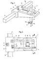
- the injection molding removal device 1 shown in FIG. 1 of the drawing has a guide bed 2 which, for example, is mounted on an injection molding machine parallel to the direction of actuation of the clamping unit for the injection mold.
- a slide can be moved along the guide bed 2, which in turn carries a cantilever arm 4 directed transversely to the guide bed 2.
- On the boom 4 is a Support 5 is arranged to be longitudinally movable, which holds a suspension link 6, which is arranged to be movable in support 5 in the upward and downward direction.
- an injection molding gripper 7 which is adjustable on the one hand about a vertical axis 8 relative to the hanging member 6, on the other hand can be pivoted relative to it about a horizontal axis 9 and can also be rotated about a longitudinal axis 10-10 .
- the injection molding removal device 1 according to FIG. 1 thus forms a manipulator, as it were, which has three linear movement coordinates and whose injection molding gripper 7 can also be displaced about three further joint axes.
- An important structural design feature of the injection molding removal device 1 is that not only the drive 11 for the sliding movement of the slide 3 along the guide bed 2 and the drive 12 for the longitudinal movement of the support 5 on the boom 4 above the guide bed 2 sit on the slide 3 , but also the drive 13, by means of which the suspension link 6 can be raised and lowered in the vertical direction relative to the support 5.
- the drive 11 for the slide 3 interacts directly via a pinion 14 with a toothing 15 on the guide bed 2
- the drive 13 for the support 5 works on a belt or chain drive 20 which is installed in the longitudinal direction of the boom 4 and which also runs with his one drive strand is connected to the support 5.
- a spindle drive could also replace the belt or chain drive 20.
- the drive 13 for the suspension link 6 works on at least one shaft, which is mounted lying in the boom 4 parallel to its longitudinal direction.
- the shaft 16 works in the manner of a lead screw, that is to say over a driver extending over its entire length, with a transmission element 17 designed as a torque sleeve.
- This transmission element 17 is non-rotatably, but axially displaceable, in constant engagement with the shaft 16, its part rotatable relative to the support 5 carrying a pinion 18, which is in constant engagement with a rack 19 fastened to the hanging link 6 and extending in the longitudinal direction thereof.
- the shaft 16 not only forms a transmission means for generating the drive movement for the suspension link 6, but also a longitudinal guide for the support 5 on the boom 4.
- the suspension link 6 is formed from two telescopically displaceable longitudinal sections, the two shafts 16 and 16 'can work with the same direction of rotation. However, it would then make sense to choose the drive ratio between the second shaft 16 'and the lower telescopic part of the hanging link 6 to be larger, for example twice as large, as the ratio between the first shaft and the upper telescopic part of the hanging link 6. It would then namely created a differential drive for the hanging link 6, which would allow a faster lifting and lowering movement of the molding gripper 7.
- suspension link 6 is expediently given a triple guide in the support 5.
- This is formed on the one hand by the rack 19, which cooperates with track disks 21 and 22 arranged on both sides of the pinion 18.
- two pairs of track rollers 23 'and 23 are rotatably mounted in the support 5, with which guide rods 24', 24" engage, which are in turn connected to the suspension link 6 by holding elements 25 along the entire length.
- the torque bushings used as transmission elements between the shafts 16 and 16 ', the support 5 and the suspension link 6 have a previously known type. With them, an obstacle-free axial displacement can be made possible by a ball seated in a longitudinal groove of the shaft and held in the sleeve, but the ball lying in the longitudinal groove when the shaft rotates Wave causes an entrainment effect for a part of the sleeve, which forms the pinion 18, which meshes with the rack 19 made of wear-resistant polyamide.
Abstract
Es wird eine Spritzling-Entnahmevorrichtung 1 für Spritzgießmaschinen geschaffen, die bei vermindertem Konstruktionsgewicht eine exakte Bewegungssteuerung des Spritzlinggreifers 7 gewährleistet. Bei ihr ist an einem parallel zur Betätigungsrichtung der Schließeinheit für das Spritzwerkzeug ausgerichteten Führungsbett 2 ein Schlitten 3 verfahrbar, der wiederum einen quer dazu verlaufenden Ausleger 4 mit einem daran längsverfahrbaren Support 5 trägt, in dem ein verstellbares Hängeglied 6 sitzt, das am unteren Ende den Spritzlinggreifer 7 trägt, der wiederum um mindestens zwei jeweils rechtwinklig zueinander gerichtete Gelenke 8, 9, 10 relativ zum Hängeglied 6 verstellbar ist. Außer dem Antrieb 11 für den Schlitten 3 und dem Antrieb 12 für den Support 5 ist auch der Antrieb 13 für das Hängeglied 6 auf dem Schlitten 3, und zwar oberhalb des Führungsbettes 2 angeordnet, so daß dessen Gewicht den Ausleger 4, den Support 5 und das Hängeglied 6 nicht belastet.An injection molding removal device 1 for injection molding machines is created, which ensures exact movement control of the injection molding gripper 7 with a reduced construction weight. In this case, a slide 3 can be moved on a guide bed 2 aligned parallel to the actuating direction of the clamping unit for the injection molding tool, which in turn carries a cross-arm 4 with a longitudinally movable support 5 in which an adjustable hanging member 6 sits, which at the lower end is the Injection molding gripper 7 carries, which in turn is adjustable relative to the hanging link 6 by at least two joints 8, 9, 10 each oriented at right angles to one another. In addition to the drive 11 for the slide 3 and the drive 12 for the support 5, the drive 13 for the suspension link 6 is arranged on the slide 3, above the guide bed 2, so that its weight is the boom 4, the support 5 and the link 6 is not loaded.
Description
Die Erfindung betrifft eine Vorrichtung zur Spritzling-Entnahme aus dem geöffneten Spritzwerkzeug von Spritzgießmaschinen, bei welcher an einem parallel zur Betätigungsrichtung der Schließeinheit für das Spritzwerkzeug ausgerichteten Führungsbett ein Schlitten verfahrbar sitzt, der wiederum einen quer dazu verlaufenden Ausleger mit einem daran längs verfahrbaren Support trägt, in dem ein in Auf- und Abwärtsrichtung verstellbares Hängeglied sitzt, das am unteren Ende einen Spritzlinggreifer trägt, welcher wiederum um mindestens zwei jeweils rechtwinklig zueinander gerichtete Gelenke relativ zum Hängeglied verstellbar ist.The invention relates to a device for injection molding removal from the open injection mold of injection molding machines, in which a slide is movably seated on a guide bed aligned parallel to the actuation direction of the clamping unit for the injection mold, which carriage in turn carries a cross-arm with a support that can be moved longitudinally thereon. in which an up and down adjustable link sits, which carries at the lower end an injection molding gripper, which in turn is adjustable relative to the link by at least two joints, each directed at right angles to each other.
Bei Spritzling-Entnmahmevorrichtungen dieser Art ist es bekannt, den Antrieb zum Verfahren des Schlittens entlang dem Führungsbett, wie auch den Antrieb zum Verfahren des Supports entlang dem Ausleger auf dem Schlitten zu montieren und dabei die Energiezuführung zu diesen Antrieben über Energieführungs-Schleppvorrichtungen zu bewirken, die an den Schlitten angeschlossen sind und entlang dem Führungsbett für diesen entsprechend der jeweiligen Schlittenbewegung verlagert werden können.In the case of injection molding removal devices of this type, it is known to mount the drive for moving the slide along the guide bed, as well as the drive for moving the support along the boom on the slide, and in doing so to bring about the energy supply to these drives via energy supply towing devices, which are connected to the carriage and can be moved along the guide bed for this according to the respective carriage movement.
Der Antrieb für die Auf- und Abwärtsbewegung des Hängegliedes, wie auch die Antriebe für das Öffnen und Schließen sowie das Verdrehen und Verschwenken des von diesem getragenen Spritzlinggreifers werden bei den bekannten Spritzling-Entnahmevorrichtungen hingegen von dem auf dem Ausleger verfahrbaren Support für das Hängeglied aufgenommen.The drive for the up and down movement of the hanging link, as well as the drives for opening and closing as well as turning and pivoting of the getra In contrast, in the known injection molding removal devices, the injection molding gripper is picked up by the support for the hanging link which can be moved on the boom.
Diese bekannte Ausgestaltung der Spritzling-Entnahmevorrichtungen ist nicht nur deshalb nachteilig, weil auch der Support mit entlang des Auslegers bewegbaren Energiezuführungs-Schleppvorrichtungen zusammenarbeiten muß. Vielmehr wird der Ausleger nicht nur durch das Gewicht des Supports und des von diesem getragenen Hängegliedes beansprucht, sondern zusätzlich noch durch die vom Support bzw. vom Hängeglied getragenen Antriebe.This known design of the injection molding removal devices is disadvantageous not only because the support must also cooperate with energy supply towing devices that can be moved along the boom. Rather, the boom is not only stressed by the weight of the support and the hanging link carried by it, but also by the drives carried by the support or hanging link.
Um eine exakte Bewegungssteuerung des Spritzlinggreifers relativ zur Schließeinheit bzw. zum Spritzwerkzeug der Spritzgießmaschine bei frei progammierbarer Auslegung der Spritzling-Entnahmevorrichtung zu gewährleisten ist es daher bei den bekannten Spritzling-Entnahmevorrichtungen notwendig, eine entsprechend steife und damit baulich aufwendige Auslegung aller zusammenarbeitenden Funktionseinheiten vorzusehen.In order to ensure exact control of the movement of the injection molding gripper relative to the clamping unit or the injection mold of the injection molding machine with a freely programmable design of the injection molding removal device, it is therefore necessary in the known injection molding removal devices to provide a correspondingly rigid and thus structurally complex design of all cooperating functional units.
Die Erfindung bezweckt die Vermeidung dieser Unzulänglichkeiten. Es liegt ihr deshalb die Aufgabe zugrunde, eine gattungsgemäße Spritzling-Entnahmevorrichtung zu schaffen, die mit relativ geringem Konstruktionsgewicht erstellt werden kann, trotzdem aber eine sehr exakte Steuerbewegung des Spritzlinggreifers relativ zur Schließeinheit bzw. zum Spritzwerkzeug sicherstellt.The purpose of the invention is to avoid these shortcomings. It is therefore the object of the invention to create a generic injection molding removal device which can be produced with a relatively low construction weight, but which nevertheless ensures a very precise control movement of the injection molding gripper relative to the clamping unit or the injection mold.
Gelöst wird diese Aufgabe erfindungsgemäß durch die Kennzeichnungsmerkmale des Anspruchs 1, nämlich dadurch, daß außer dem Antrieb für den Schlitten und dem Antrieb für den Support auch der Antrieb für das Hängeglied auf dem Schlitten oberhalb des Führungsbettes sitzt, daß dabei die Führung für den Support am Ausleger aus mindestens einer in dessen Längsrichtung verlaufenden, drehbaren Welle besteht, daß diese Welle einerseits mit dem Antrieb für das Hängeglied auf dem Schlitten gekuppelt ist und andererseits einen sich über ihre ganze Länge erstreckenden Mitnehmer aufweist, und daß im Support ausschließlich drehbar ein längs schiebbar aber drehfest mit dem Mitnehmer der Welle in Eingriff stehendes Übertragungselement gelagert ist, das mit einem Lineartrieb des Hängegliedes in ständiger Antriebsverbindung steht.This object is achieved according to the invention by the characterizing features of claim 1, namely in that, in addition to the drive for the slide and the drive for support, the drive for the suspension link sits on the slide above the guide bed, in that the guide for the support on the boom consisting of at least one rotating shaft running in its longitudinal direction, that this shaft is coupled on the one hand to the drive for the hanging link on the slide and on the other hand has a driver extending over its entire length, and that the support is only rotatable a longitudinally slidable but non-rotatably mounted transmission element which is in engagement with the driver of the shaft and which is in constant drive connection with a linear drive of the suspension link.
Vorteilhaft bei dieser Ausgestaltung ist, daß der Ausleger lediglich das Gewicht des Supports sowie das von diesem getragene Hängeglied aufzunehmen hat und daher entsprechend leichter gebaut werden kann. Nach Anspruch 2 erweist es sich als besonders vorteilhaft, wenn erfindungsgemäß das Übertragungselement aus mindestens einer Drehmomentbüchse besteht, die zugleich ein Längsführungselement für den Support auf der Welle bzw. am Ausleger bildet.It is advantageous in this embodiment that the boom only has to take up the weight of the support and the suspension link carried by it and can therefore be built correspondingly more easily. According to
Weiterhin ist es nach der Erfindung zweckmäßig, wenn gemäß Anspruch 3 der drehantreibbare Teil der Büchse mit einem Ritzel verbunden ist, dieses vorzugsweise trägt, wobei das Ritzel mit einer Zahnstange am Hängeglied ständig in Eingriff steht, die vorzugsweise aus einem verschleißfesten Polyamid-Kunststoff mit relativ geringem Gewicht hergestellt werden kann.Furthermore, it is expedient according to the invention if, according to
Als besonders vorteilhaft kann es sich nach der Erfindung aber erweisen, wenn gemäß Anspruch 4 zwei parallele Wellen mit Übertragungselementen im Ausleger angeordnet sowie mit dem Support in Wirkverbindung gehalten sind. In diesem Falle bewährt es sich nach Anspruch 5 weiterhin, daß die beiden Wellen für Synchronbewegung mit dem Antrieb für das Hängeglied gekuppelt sind.According to the invention, however, it can prove to be particularly advantageous if, according to
In besonders vorteilhafter Weise läßt sich die erfindungsgemäße Spritzling-Entnahmevorrichtung dadurch weiterbilden, daß gemäß Anspruch 6 das Hängeglied aus zwei teleskopartig zueinander relativ verschiebbaren Längenabschnitten besteht, von denen jeder eine eigene Zahnstange trägt und wobei jede Zahnstange mit einem Übertragungselement einer der beiden Wellen in Eingriff steht.In a particularly advantageous manner, the injection molding removal device according to the invention can be further developed in that, according to
Weitere Merkmale und Vorteile des Gegenstandes der Erfindung werden an in der Zeichnung dargestellten Ausführungsbeispielen nachfolgend näher erläutert. Es zeigen
- Figur 1 in vereinfachter räumlicher Ansichtsdarstellung den Grundaufbau einer Spritzling-Entnahmevorrichtung,
Figur 2 die Spritzling-Entnahmevorrichtung in Pfeilrichtung II der Fig. l gesehenFigur 3 in größerem Maßstab einen Schnitt entlang der Linie III-III in Fig. 2 undFigur 4 in vergrößerter Draufsichtdarstellung den in Fig. 2 mit IV gekennzeichneten Teilbereich der Spritzling-Entnahmevorrichtung.
- FIG. 1 shows the basic structure of an injection molding removal device in a simplified spatial view,
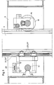
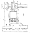
- Figure 2 seen the molding removal device in the direction of arrow II of FIG
- Figure 3 on a larger scale a section along the line III-III in Fig. 2 and
- FIG. 4 shows an enlarged top view of the portion of the injection molding removal device identified by IV in FIG. 2.
Die in Fig. l der Zeichnung dargestellte Spritzling-Entnahmevorrichtung 1 weist ein Führungbett 2 auf, welches bspw. parallel zur Betätigungsrichtung der Schließeinheit für das Spritzwerkzeug an einer Spritzgießmaschine montiert wird. Längs des Führungsbettes 2 ist dabei ein Schlitten verfahrbar, der wiederum einen quer zum Führungsbett 2 gerichteten Ausleger 4 als Kragarm trägt. Auf dem Ausleger 4 ist ein Support 5 längsverfahrbar angeordnet, der ein Hängeglied 6 hält, welches im Support 5 in Auf- und Abwärtsrichtung verfahrbar angeordnet ist.The injection molding removal device 1 shown in FIG. 1 of the drawing has a
Am unteren Ende des Hängegliedes 6 befindet sich ein Spritzlinggreifer 7, der einerseits um eine vertikale Achse 8 relativ zum Hängeglied 6 verstellbar ist, andererseits um eine horizontale Achse 9 relativ dazu verschwenkt werden kann und sich schließlich auch noch um eine Längsachse 10-10 verdrehen läßt.At the lower end of the hanging
Die Spritzling-Entnahmevorrichtung 1 nach Fig. l bildet also gewissermaßen einen Manipulator, welcher drei lineare Bewegungskoordinaten hat und dessen Spritzlinggreifer 7 darüber hinaus noch um drei weitere Gelenkachsen verlagert werden kann.The injection molding removal device 1 according to FIG. 1 thus forms a manipulator, as it were, which has three linear movement coordinates and whose
Ein wichtiges bauliches Ausbildungsmerkmal der Spritzling-Entnahmevorrichtung 1 liegt darin, daß nicht nur der Antrieb 11 für die Verschiebebewegung des Schlittens 3 entlang dem Führungsbett 2 und der Antrieb 12 zur Längsbewegung des Supports 5 auf dem Ausleger 4 oberhalb des Führungsbettes 2 auf dem Schlitten 3 sitzen, sondern auch noch der Antrieb 13, mit dessen Hilfe das Hängeglied 6 inm Vertikalrichtung relativ zum Support 5 gehoben und gesenkt werden kann.An important structural design feature of the injection molding removal device 1 is that not only the
Lediglich der Antrieb zum Öffnen und Schließen des Spritzlinggreifers 7 sowie die drei Antriebe zur Verlagerung desselben um die Gelenkachsen 8, 9 und 10 sind am und/oder im Hängeglied 6 selbst untergebracht. Da sie jedoch nur relativ geringe Stellkräfte zu erzeugen haben, können sie relativ leicht gebaut werden, so daß sie den Ausleger 4 über den Support 5 nicht wesentlich beanspruchen.Only the drive for opening and closing the
Während der Antrieb 11 für den Schlitten 3 unmittelbar über ein Ritzel 14 mit einer Verzahnung 15 am Führungsbett 2 zusammenwirkt, arbeitet der Antrieb 13 für den Support 5 auf einen Riemen- oder Kettentrieb 20, welcher in Längsrichtung des Auslegers 4 verlaufend eingebaut ist und der mit seinem einen Antriebstrum an den Support 5 angeschlossen ist. Selbstverständlich könnte anstelle des Riemen- oder Kettentriebes 20 auch ein Spindeltrieb treten.While the
Der Antrieb 13 für das Hängeglied 6 arbeitet auf mindestens eine Welle, die im Ausleger 4 parallel zu dessen Längsrichtung liegend gelagert ist. Die Welle 16 arbeitet dabei nach Art einer Leitspindel, also über einen sich über ihre ganze Länge erstreckenden Mitnehmer, mit einem als Drehmomentbüchse ausgebildeten Übertragungselement 17 zusammen. Dieses Übertragungselement 17 steht dabei drehfest, jedoch axial verschiebbar mit der Welle 16 in ständigem Eingriff, wobei ihr relativ zum Support 5 drehbares Teil ein Ritzel 18 trägt, das mit einer am Hängeglied 6 befestigten und in dessen Längsrichtung verlaufenden Zahnstange 19 in ständigem Eingriff steht.The
Die Welle 16 bildet aber nicht nur ein Übertragungsmittel zur Erzeugung der Antriebsbewegung für das Hängeglied 6, sondern zugleich auch eine Längsführung für den Support 5 am Ausleger 4.The
Aus Fig. 3 geht hervor, daß im Einbaubereich des Riemen-oder Kettenantriebs 20 parallel zur Welle 16 noch eine Welle 16' in den Ausleger 4 eingebaut werden kann, die ebenfalls mit dem Antrieb 13 in Verbindung steht und synchron zur Welle 16 bewegt wird. Auch diese Welle 16' arbeitet dabei, ebenso wie die Welle 16, über eine Büchse 17 mit dem Support 5 zusammen und bildet mithin eine weitere Längsführung für diesen. Das relativ zum Support drehbewegliche Teil dieses Übertragungselementes trägt dabei ebenfalls ein Ritzel 18, welches mit einer Zahnstange 19 kämmt, die am Hängeglied 6 befestigt ist. Wenn beide Wellen 16 und 16' auf ein einstückiges Hängeglied 6 einwirken, dann ist es natürlich notwendig, daß sie mit zueinander entgegengesetzten Drehrichtungen umlaufen. Wird hingegen das Hängeglied 6 aus zwei teleskopisch relativ zueinander verschiebbaren Längenabschnitten gebildet, dann können die beiden Wellen 16 und 16' mit übereinstimmender Drehrichtung arbeiten. Es wäre jedoch dann sinnvoll, die Antriebsübersetzung-zwischen der zweiten Welle 16' und dem unteren Teleskopteil des Hängegliedes 6 größer, bspw. doppelt so groß, zu wählen, wie die Übersetzung zwischen der ersten Welle und dem oberen Teleskopteil des Hängegliedes 6. Es würde dann nämlich ein Differentialantrieb für das Hängeglied 6 geschaffen, der eine schnellere Heb-und Senkbewegung des Spritzlinggreifers 7 zulassen würde.3 shows that in the installation area of the belt or
Aus den Fig. 3 und 4 ist noch entnehmbar, daß das Hängeglied 6 zweckmäßigerweise im Support 5 eine Dreifachführung erhält. Diese wird einerseits von der Zahnstange 19 gebildet, die mit beidseits des Ritzels 18 angeordneten Spurscheiben 21 und 22 zusammenarbeitet. Andererseits sind im Support 5 noch zwei Spurrollen-Paare 23' und 23" drehbar gelagert, mit denen Führungsstangen 24', 24" in Eingriff strehen, die wiederum durch Halteelemente 25 auf der ganzen Länge mit dem Hängeglied 6 in Verbindung stehen.3 and 4 that the
Es sei noch erwähnt, daß die als Übertragungselemente zwischen den Wellen 16 und 16', dem Support 5 und dem Hängeglied 6 benutzten Drehmomentbüchsen eine vorbekannte Bauart aufweisen. Bei ihnen läßt sich durch eine in einer Längsrille der Welle sitzende und in der Büchse gehaltene Kugel eine behinderungsfreie Axialverschiebung ermöglichen, wobei jedoch die in der Längsrille liegende Kugel beim Drehen der Welle einen Mitnahmeeffekt für einen Teil der Büchse bewirkt, der das Ritzel 18 bildet, welches mit der Zahnstange 19 aus verschleißfestem Polyamid kämmt.It should also be mentioned that the torque bushings used as transmission elements between the
Claims (7)
dadurch gekennzeichnet ,
characterized ,
dadurch gekennzeichnet ,
daß das Übertragungselement (17) aus mindestens einer Drehmomentbüchse besteht, die zugleich ein Längsführungselement für den Support (5) auf der Welle (16) bzw. am Ausleger (4) bildet.2. Device according to claim 1,
characterized ,
that the transmission element (17) consists of at least one torque sleeve, which at the same time forms a longitudinal guide element for the support (5) on the shaft (16) or on the arm (4).
dadurch gekennzeichnet ,
daß der drehantreibbare Teil der Drehmomentbüchse (17) mit einem Ritzel (18) verbunden ist, dieses vorzugsweise trägt, wobei das Ritzel (18) mit einer Zahnstange (19) am Hängeglied (6) ständig in Eingriff steht.3. Device according to one of claims 1 and 2,
characterized ,
that the rotationally drivable part of the torque sleeve (17) is connected to a pinion (18), which preferably carries this, the pinion (18) with a rack (19) on the hanging link (6) being constantly engaged.
dadurch gekennzeichnet ,
daß zwei parallele Wellen (16, 16') mit Übertragungselementen (17) im Ausleger (4) angeordnet sowie mit dem Support (5) in Wirkverbindung gehalten sind (17); Fig. 3).4. Device according to one of claims 1 to 3,
characterized ,
that two parallel shafts (16, 16 ') with transmission elements (17) are arranged in the boom (4) and are held in operative connection with the support (5) (17); Fig. 3).
dadurch gekennzeichnet ,
daß die beiden Wellen (16 und 16') für Synchronbewegung mit dem Antrieb (13) für das Hängeglied (6) gekuppelt sind.5. Device according to one of claims 1 to 4,
characterized ,
that the two shafts (16 and 16 ') are coupled for synchronous movement with the drive (13) for the suspension link (6).
dadurch gekennzeichnet ,
daß das Hängeglied (6) aus zwei teleskopartig zueinander relativ verschiebbaren Längenabschnitten besteht, von denen jeder eine eigene Zahnstange (19) trägt, wobei jede Zahnstange (19) mit einem Übertragungselement (17) einer der beiden Wellen (16 und 16') in Eingriff steht, eobei vorzugsweise die Übersetzungsverhältnisse für die Antriebseingriffe beider Längenabschnitte des Hängegliedes6. Device according to one of claims 1 to 5,
characterized ,
that the suspension link (6) consists of two telescopically displaceable longitudinal sections, each of which carries its own rack (19), each rack (19) with a transmission element (17) one of the two shafts (16 and 16 ') is engaged, preferably the transmission ratios for the drive interventions of both longitudinal sections of the suspension link
Applications Claiming Priority (2)
| Application Number | Priority Date | Filing Date | Title |
|---|---|---|---|
| DE19863613074 DE3613074A1 (en) | 1986-04-18 | 1986-04-18 | SPRAYLING REMOVAL DEVICE FOR INJECTION MOLDING MACHINES |
| DE3613074 | 1986-04-18 |
Publications (2)
| Publication Number | Publication Date |
|---|---|
| EP0241820A2 true EP0241820A2 (en) | 1987-10-21 |
| EP0241820A3 EP0241820A3 (en) | 1989-03-29 |
Family
ID=6298959
Family Applications (1)
| Application Number | Title | Priority Date | Filing Date |
|---|---|---|---|
| EP87104955A Withdrawn EP0241820A3 (en) | 1986-04-18 | 1987-04-03 | Injected part take-out device for injection-moulding machines |
Country Status (5)
| Country | Link |
|---|---|
| US (1) | US4732554A (en) |
| EP (1) | EP0241820A3 (en) |
| AU (1) | AU7119387A (en) |
| BR (1) | BR8701812A (en) |
| DE (1) | DE3613074A1 (en) |
Cited By (3)
| Publication number | Priority date | Publication date | Assignee | Title |
|---|---|---|---|---|
| FR2639572A1 (en) * | 1988-11-29 | 1990-06-01 | Renault | MULTI-AXIS ROBOT |
| CN104476740A (en) * | 2014-11-12 | 2015-04-01 | 湖北荆硕自动化设备有限公司 | Multi-mechanical arm taking-out device |
| CN104669236A (en) * | 2013-11-29 | 2015-06-03 | 徐建 | Side-obtaining truss tri-axial servo robot |
Families Citing this family (28)
| Publication number | Priority date | Publication date | Assignee | Title |
|---|---|---|---|---|
| DE3830964A1 (en) * | 1988-09-12 | 1990-03-22 | Karl Hehl | INJECTION MOLDING MACHINE WITH A DEVICE FOR REMOVING THE INJECTION PARTS FROM THE INJECTION TOOL |
| US5185119A (en) * | 1988-01-29 | 1993-02-09 | Husky Injection Molding Systems Ltd. | Injection molding process |
| US4867938B1 (en) * | 1988-01-29 | 1998-05-26 | Husky Injection Molding | Sequential injection molding process |
| US5242014A (en) * | 1988-11-30 | 1993-09-07 | Nippon Steel Corporation | Continuous casting method and apparatus for implementing same method |
| US5372319A (en) * | 1989-10-03 | 1994-12-13 | Globe Products Inc. | Apparatus for loading and unloading workpieces |
| US5000654A (en) * | 1989-12-28 | 1991-03-19 | Star Seiki Co., Ltd. | Reciprocating drive apparatus for automatic molding removing machine |
| DE4017796C1 (en) * | 1990-06-01 | 1991-12-19 | Richard 8057 Eching De Herbst | |
| US5139411A (en) * | 1991-04-01 | 1992-08-18 | Polacinski Michel C | Apparatus for reducing wear on mold ejection systems |
| US5354194A (en) * | 1993-01-28 | 1994-10-11 | Husky Injection Molding Systems Ltd. | High speed molded product retrieval device |
| US5513970A (en) * | 1993-05-10 | 1996-05-07 | Sony Corporation | Robot for ejection of an object from between two bodies |
| US6086808A (en) * | 1997-08-19 | 2000-07-11 | Universal Ventures | Repositioning of articles between different positions within an intermittently accessible space |
| JP2979404B1 (en) * | 1998-12-08 | 1999-11-15 | 株式会社ユーシン精機 | Control method of injection molded product removal device and injection molded product removal device implementing the same |
| JP2001252954A (en) * | 2000-03-13 | 2001-09-18 | Star Seiki Co Ltd | Machine and method for taking out molding |
| DE10234041B3 (en) * | 2002-07-26 | 2004-02-19 | Karl Hehl | Removal device for a plastic injection molding machine |
| US20040084809A1 (en) * | 2002-11-05 | 2004-05-06 | Vanderploeg James A. | Side shuttle apparatus and method for an injection molding machine |
| NL1023776C2 (en) * | 2003-06-30 | 2005-01-03 | Roboxis B V | Robot. |
| DE102004025416B4 (en) * | 2004-05-24 | 2013-01-17 | Siemens Aktiengesellschaft | Computer-aided determination method for additional position setpoint values for a positionally movable additional element of a machine, in particular a production machine |
| CN101306570B (en) * | 2007-05-17 | 2011-01-05 | 鸿富锦精密工业(深圳)有限公司 | Mold device |
| US7708919B2 (en) * | 2008-05-08 | 2010-05-04 | Delphi Technologies, Inc. | Sprue removal in an injection molding machine |
| TW201119835A (en) * | 2009-12-10 | 2011-06-16 | Quanta Comp Inc | Pre-heat apparatus, injection molding with the same, and method of pre-heating injection molding |
| CA2794752C (en) | 2010-04-01 | 2018-07-17 | Athena Automation Ltd. | Injection molding machine with integrated part handling apparatus |
| JP5764408B2 (en) * | 2011-06-30 | 2015-08-19 | 株式会社ユーシン精機 | Mold take-out machine |
| CN104669239A (en) * | 2013-11-29 | 2015-06-03 | 徐建 | Triaxial truss type high-speed servo robot |
| CN104669238A (en) * | 2013-11-29 | 2015-06-03 | 徐建 | Drawing beam of triaxial high-speed servo robot |
| JP6465615B2 (en) * | 2014-10-22 | 2019-02-06 | 株式会社ユーシン精機 | Mold take-out machine |
| CN106142482B (en) * | 2016-08-20 | 2018-01-02 | 河北工业大学 | Medical throat cover production line laryngeal mask automatic picking device |
| US11078016B2 (en) * | 2018-09-04 | 2021-08-03 | HanBin Kim | Mobile sorting systems |
| CN111633631B (en) * | 2020-05-07 | 2021-08-06 | 邵东县环兴打火机制造有限公司 | A manipulator for moulding plastics |
Citations (7)
| Publication number | Priority date | Publication date | Assignee | Title |
|---|---|---|---|---|
| US3665148A (en) * | 1971-04-07 | 1972-05-23 | Gen Motors Corp | Six-axis manipulator |
| US4368018A (en) * | 1981-10-14 | 1983-01-11 | Husky Injection Molding Systems Inc. | Transporter for injection-molded parts or inserts therefor |
| FR2521666A1 (en) * | 1982-02-13 | 1983-08-19 | Teramachi Hiroshi | UNLIMITED SLIDING CANELE COUPLING |
| EP0122146A1 (en) * | 1983-04-14 | 1984-10-17 | Westinghouse Electric Corporation | General purpose orthogonal axes manipulator system |
| JPS60196320A (en) * | 1984-03-17 | 1985-10-04 | Star Seiki:Kk | Automatic take-out device of injection-molded article |
| EP0170773A1 (en) * | 1984-06-05 | 1986-02-12 | KUKA Schweissanlagen GmbH | Rack and pinion drive for the generation of a relative motion between two machine parts guided relative to one another |
| DE8624943U1 (en) * | 1986-09-18 | 1986-10-30 | GMG-Gemminger Maschinenbau GmbH, 75050 Gemmingen | Telescopically extendable handling or transport device |
Family Cites Families (4)
| Publication number | Priority date | Publication date | Assignee | Title |
|---|---|---|---|---|
| US3760956A (en) * | 1971-08-23 | 1973-09-25 | Burch Controls Inc | Industrial robot |
| JPS6110968Y2 (en) * | 1981-06-04 | 1986-04-08 | ||
| SE430682B (en) * | 1982-05-06 | 1983-12-05 | Asea Ab | SET AND DEVICE TO PROVIDE AND REMOVE DETAILS AT A ROBOT OPERATED MACHINE |
| US4571320A (en) * | 1984-10-31 | 1986-02-18 | General Motors Corporation | Method and apparatus for loading and unloading sheet molding compound in and from a press |
-
1986
- 1986-04-18 DE DE19863613074 patent/DE3613074A1/en not_active Withdrawn
-
1987
- 1987-04-03 EP EP87104955A patent/EP0241820A3/en not_active Withdrawn
- 1987-04-08 AU AU71193/87A patent/AU7119387A/en not_active Abandoned
- 1987-04-15 BR BR8701812A patent/BR8701812A/en unknown
- 1987-04-16 US US07/039,535 patent/US4732554A/en not_active Expired - Fee Related
Patent Citations (7)
| Publication number | Priority date | Publication date | Assignee | Title |
|---|---|---|---|---|
| US3665148A (en) * | 1971-04-07 | 1972-05-23 | Gen Motors Corp | Six-axis manipulator |
| US4368018A (en) * | 1981-10-14 | 1983-01-11 | Husky Injection Molding Systems Inc. | Transporter for injection-molded parts or inserts therefor |
| FR2521666A1 (en) * | 1982-02-13 | 1983-08-19 | Teramachi Hiroshi | UNLIMITED SLIDING CANELE COUPLING |
| EP0122146A1 (en) * | 1983-04-14 | 1984-10-17 | Westinghouse Electric Corporation | General purpose orthogonal axes manipulator system |
| JPS60196320A (en) * | 1984-03-17 | 1985-10-04 | Star Seiki:Kk | Automatic take-out device of injection-molded article |
| EP0170773A1 (en) * | 1984-06-05 | 1986-02-12 | KUKA Schweissanlagen GmbH | Rack and pinion drive for the generation of a relative motion between two machine parts guided relative to one another |
| DE8624943U1 (en) * | 1986-09-18 | 1986-10-30 | GMG-Gemminger Maschinenbau GmbH, 75050 Gemmingen | Telescopically extendable handling or transport device |
Non-Patent Citations (1)
| Title |
|---|
| PATENT ABSTRACTS OF JAPAN, Band 10, Nr. 44 (M-455)[2101], 21. Februar 1986; & JP-A-60 196 320 (SUTAA SEIKI K.K.) 04-10-1985 * |
Cited By (4)
| Publication number | Priority date | Publication date | Assignee | Title |
|---|---|---|---|---|
| FR2639572A1 (en) * | 1988-11-29 | 1990-06-01 | Renault | MULTI-AXIS ROBOT |
| EP0371872A1 (en) * | 1988-11-29 | 1990-06-06 | Regie Nationale Des Usines Renault | Multiaxis robot |
| CN104669236A (en) * | 2013-11-29 | 2015-06-03 | 徐建 | Side-obtaining truss tri-axial servo robot |
| CN104476740A (en) * | 2014-11-12 | 2015-04-01 | 湖北荆硕自动化设备有限公司 | Multi-mechanical arm taking-out device |
Also Published As
| Publication number | Publication date |
|---|---|
| AU7119387A (en) | 1987-10-22 |
| EP0241820A3 (en) | 1989-03-29 |
| BR8701812A (en) | 1988-01-26 |
| US4732554A (en) | 1988-03-22 |
| DE3613074A1 (en) | 1987-10-29 |
Similar Documents
| Publication | Publication Date | Title |
|---|---|---|
| EP0241820A2 (en) | Injected part take-out device for injection-moulding machines | |
| DE3303925C2 (en) | Massage facility | |
| EP0868964A1 (en) | Apparatus providing a defined positioning and orientation of at least one platform | |
| EP0338334B1 (en) | Programmable machine for treating work having predetermined outlines | |
| DE2800828A1 (en) | DEVICE FOR TURNING WORKPIECES | |
| DE3505836A1 (en) | INJECTION MOLDING MACHINE WITH SPLASHING REMOVAL DEVICE | |
| DE3326962A1 (en) | INDUSTRIAL ROBOT WITH TWO-PIECE JOINT ARM | |
| DE102008029451B4 (en) | Device for the automatic removal of objects from containers | |
| DE3717957C2 (en) | ||
| EP1566243B1 (en) | Device for positioning and driving a worktool | |
| DE2433954B2 (en) | HANDLING DEVICE | |
| CH656327A5 (en) | SHAKER. | |
| DE1574639A1 (en) | Device for adjusting the position of a material strip moved in its longitudinal direction with respect to a reference plane | |
| DE102013112802B4 (en) | Robotic arm with flexible tension element | |
| CH674976A5 (en) | Handling system for use in confined spaces | |
| EP0132448B1 (en) | Table with adjustable table top | |
| DE2155125C3 (en) | Lifting device of a gripper bank of an automatic tube changing device | |
| DE4012645C1 (en) | ||
| DE4342016A1 (en) | Device for adjusting the height and / or inclination of a table top | |
| DE4016987C1 (en) | Computer controlled positioning appts. - has drive carriage coupled to two threaded spindles for displacing drive rods | |
| DE536352C (en) | Schraem device | |
| DE2444412A1 (en) | Reciprocating sprayer for lacquer - allowing control of length and position of stroke of reciprocating mechanism relative to sprayer | |
| DE7801036U1 (en) | ELECTRICALLY ADJUSTABLE REAR MIRROR FOR VEHICLES | |
| EP1156174A1 (en) | Work scaffolding | |
| DE2706496C3 (en) | Suction device |
Legal Events
| Date | Code | Title | Description |
|---|---|---|---|
| PUAI | Public reference made under article 153(3) epc to a published international application that has entered the european phase |
Free format text: ORIGINAL CODE: 0009012 |
|
| 17P | Request for examination filed |
Effective date: 19870424 |
|
| AK | Designated contracting states |
Kind code of ref document: A2 Designated state(s): AT CH DE FR GB IT LI |
|
| RAP1 | Party data changed (applicant data changed or rights of an application transferred) |
Owner name: BATTENFELD GMBH |
|
| PUAL | Search report despatched |
Free format text: ORIGINAL CODE: 0009013 |
|
| AK | Designated contracting states |
Kind code of ref document: A3 Designated state(s): AT CH DE FR GB IT LI |
|
| 17Q | First examination report despatched |
Effective date: 19900314 |
|
| STAA | Information on the status of an ep patent application or granted ep patent |
Free format text: STATUS: THE APPLICATION HAS BEEN WITHDRAWN |
|
| 18W | Application withdrawn |
Withdrawal date: 19910327 |
|
| R18W | Application withdrawn (corrected) |
Effective date: 19910327 |
|
| RIN1 | Information on inventor provided before grant (corrected) |
Inventor name: HELLMANN, DIETER |