EP0241569B1 - Picture reproduction system for producing a digital picture - Google Patents
Picture reproduction system for producing a digital picture Download PDFInfo
- Publication number
- EP0241569B1 EP0241569B1 EP86105185A EP86105185A EP0241569B1 EP 0241569 B1 EP0241569 B1 EP 0241569B1 EP 86105185 A EP86105185 A EP 86105185A EP 86105185 A EP86105185 A EP 86105185A EP 0241569 B1 EP0241569 B1 EP 0241569B1
- Authority
- EP
- European Patent Office
- Prior art keywords
- picture
- counter
- line
- store
- picture element
- Prior art date
- Legal status (The legal status is an assumption and is not a legal conclusion. Google has not performed a legal analysis and makes no representation as to the accuracy of the status listed.)
- Expired - Lifetime
Links
Images


Classifications
-
- H—ELECTRICITY
- H04—ELECTRIC COMMUNICATION TECHNIQUE
- H04N—PICTORIAL COMMUNICATION, e.g. TELEVISION
- H04N1/00—Scanning, transmission or reproduction of documents or the like, e.g. facsimile transmission; Details thereof
- H04N1/40—Picture signal circuits
- H04N1/405—Halftoning, i.e. converting the picture signal of a continuous-tone original into a corresponding signal showing only two levels
- H04N1/4055—Halftoning, i.e. converting the picture signal of a continuous-tone original into a corresponding signal showing only two levels producing a clustered dots or a size modulated halftone pattern
- H04N1/4056—Halftoning, i.e. converting the picture signal of a continuous-tone original into a corresponding signal showing only two levels producing a clustered dots or a size modulated halftone pattern the pattern varying in one dimension only, e.g. dash length, pulse width modulation [PWM]
Definitions
- the invention relates to an image display system for generating a digital image according to the preamble of patent claim 1.
- An image processing system is also known from US Pat. No. 4,370,667 which contains a counter whose count value for successive pixel data along a write line is reset to a value which corresponds to the gray value for a pixel and which therefore supplies a counter output signal, that is proportional to the respective gray value.
- There is also an AND gate which receives the counter output signal at an input and in this case transmits a high-frequency signal from a high-frequency oscillator to a laser diode of a laser printer.
- the invention is based on the object of developing the image reproduction system mentioned at the outset in such a way that the gray value adjustment in the individual image element regions can be implemented using an electronic device which is of a simpler design and therefore less expensive to produce.
- the counter is advantageously reset whenever a period setting counter has run through a predetermined number of counting steps by which the size of a picture element in the line direction of the picture is determined. If, for example, a picture element is made up of a square of four pixels, the picture element period is two pixel widths. For picture elements with only one pixel, the picture element period is one pixel width. The counter is then set at the beginning of a respective period to a count value which corresponds to the blackening value of the image area which is to be reproduced by the image element.
- the picture element data of a picture line must be read out repeatedly so often that the number of pixels in the Y direction (transport direction of the image carrier) corresponds to the number of pixels in the X direction (write line direction).
- the period counter can also be set so that its period is smaller than the pixel period for picture elements with only one pixel, or that it is smaller than the picture element period for picture elements with more than one pixel. The count value of the counter for the line or bar width must then be reduced accordingly (Fig. 3 (a), right half).
- a table memory is arranged between the outputs of the additional line memory and the input of the counter, in which the relationship between the gray value determined by the picture element data and the counter value required for the generation of this gray value is stored Pixel data is supplied to the counter.
- the required counter value can be determined very quickly using this table memory.
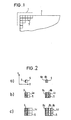
- An image memory 1 is shown schematically in FIG. 1, in which a data field 2 with a plurality of image areas 3 of an image is stored. Each image area 3 is assigned picture element data which indicate a gray value or blackening value S for the respective image area 3.
- Figures 2 (a) to 2 (c) show picture elements as they are generated for the reproduction of the digital picture.
- a picture element consists of one pixel 5 each.
- the width of the line 6 extends in the writing line direction of the laser printer 10, that is to say in the X direction, perpendicular to the Y direction.
- This width of the line 6 present within the pixel 5 is set in accordance with the density value S, which is assigned to the image area 3, which is to be reproduced with the aid of the pixel 5.
- the line width is adjustable in steps, the width of which is 1/32 of the pixel width. Overall, 5 32 + 1 different gray values can thus be generated within the pixel.
- the lines 6 and 6a, 6b are aligned one behind the other in the Y direction and can also adjoin one another with their end faces.
- toner material is deposited on the latent image built up by the pixels 5, in this case practically no transitions between the pixels adjacent in the Y direction are obtained in the toner image, so that no interfering lines run in the X direction in the reproduced image.
- Each writing line can also be shifted in the direction of the writing line compared to the previous one, in order to obtain other desired image grids.
- FIG. 2 (b) shows two picture elements 4a, 4b, which are each made up of four pixels 5 and square.
- the picture element 4a contains on its left edge a line 8 which extends in its longitudinal direction over practically two writing lines of the laser printer 10.
- the picture element 4b there are two lines 8a, 8b, which likewise extend over two writing lines in the Y direction.
- one image area 3 is reproduced either by the image element 4a or the image element 4b.
- the width or overall width of lines 8 and 8a, 8b corresponds to the desired blackening value of image area 3.
- the resolution is reduced compared to the first exemplary embodiment due to the larger image elements 4a, 4b.
- linearity and dynamics are improved. Overall, twice as many gray levels can be set within the picture elements 4a, 4b as with the picture elements 5 shown above them.
- FIG. 2 (c) Further examples of picture elements 4c, 4d are shown in FIG. 2 (c), the picture element 4c containing nine pixels 5 and a line 9 lying on the left edge, while the picture element 4d contains nine pixels 5 and three lines 9a, 9b, 9c, which extend in the longitudinal direction or Y direction over three write lines of the laser printer 10. In this case too, an image area 3 is reproduced by the image elements 4a and 4d.
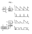
- FIG. 3 (a) shows a picture element 4e with sixteen pixels 5 for reproducing an image area 3 with a blackening value S, which is approximately 35% of the total blackening. If the width of a pixel 5 is subdivided into 32 steps, the total blackening of 100% is achieved after 128 steps, while a blackening of about 35% is obtained after 64 steps (see FIG. 4). With this blackening of approximately 35%, the picture element 4e is half-filled with a line 11 which extends in the Y direction over four write lines of the laser printer 10.
- the count value Z of a counter 12 is first set to a value which corresponds to the desired blackening S, in accordance with the blackening curve shown in FIG.
- the count value Z is 64 in this case.
- the counter 12 in FIGS. 5 and 6 is set such that it reduces the set count value to zero. As long as it counts down, it delivers a counter output signal D corresponding to FIG. 3 (c) in accordance with the counting diagram shown in FIG. 3 (b), which is used to control a laser diode 13 within a printing unit 14 of the laser printer 10. As long as the laser diode 13 is driven by the counter output signal D, the width of line 11 in FIG.
- the size of the smallest image unit for generating a digital image therefore does not correspond to that The size of a pixel but the size of a line element within the pixel whose width is only a fraction of the pixel width.
- a line with such a small line width can be generated, for example, by only minimally deflecting the laser beam.
- FIG. 5 shows an image display system according to the invention.
- This image reproduction system has a conventional computer 15, a data memory 16 with the said image memory and a text memory 17 and the laser printer 10 already mentioned.
- the laser printer 10 contains the printing unit 14 with the laser diode 13, a controller 18, a text buffer 19 for one page and a character generator 20. Text from the text memory 17 is fed page by page into the text buffer 19 and via the character generator 20 to the printing unit 14, by means of the laser diode 13, which is preceded by an amplifier 21, to be printed on the image carrier 7.
- the printing process takes place under the control of the computer 15 and the controller 18, which in turn supplies a line synchronization signal and a page synchronization signal to the computer 15 and to the data memory 16.
- the image display system has an additional unit 22 which contains the already mentioned counter 12 for line broadening, a logical OR gate 23 and two line memories 24, 25.
- the two line memories 24, 25 (line buffers) are connected on the input side to the image memory 1 and on the output side to the counter 12, the output of which in turn is connected to an input of the OR gate 23.
- the other input of the OR gate 23 is connected to the character generator 20.
- the OR gate 23 is connected to the laser diode 13 of the printing unit 14 via the amplifier 21.
- the line memories 24, 25 also receive the line synchronization signal and the page synchronization signal from the controller 18 of the laser printer 10.
- the character generator 20 supplies a text signal Te via the OR gate 23 and the amplifier 21 to the laser diode 13.
- pixel data from the image memory 1 for the next two write lines of the laser printer 10 are stored line by line in the line memories 24 and 25.
- the picture element data from the line memory 24 are transferred in sequence to the counter 12, the count value Z of which is reset by the successive picture element data along a write line to a value which corresponds to the respective data value or blackening value for a picture element, and for as long as a counter output signal D delivers until its count Z has reached zero.
- This counter output signal D is also transmitted via the OR gate 23 and the amplifier 21 to the laser diode 13 in order to print an image line on the image carrier 7.
- the lines are generated along the image line within the individual image elements with a width that corresponds to the respective count value Z of the counter 12.
- the line width is thus controlled by the counter output signal D of the counter 12.
- the text signal Te and the counter output signal D can also be generated simultaneously, so that text can be written within an image area.
- the counter 12 is reset (FIG. 6) whenever a period setting counter 26 has passed a predetermined number of counting steps by which the size of a picture element in the direction of the writing line is determined.
- the period P is thus set by the period setting counter 26.
- the count value of the period setting counter 26 is periodically set to a count value which is supplied from an 8-bit register 27.
- the count in the 8-bit register 27 is stored by the computer in accordance with the pixel size. For example, if the count 32 is in accordance with FIG. 2 (a), the picture element period P is the pixel period. With a count of 64 for the period setting counter 26, the picture element period P is two pixel periods, and so on.
- a clock signal T is supplied in dependence on the time t, which causes the counter 12 to be set to its count value Z for the following picture element period P. Both counters 26 and 12 are clocked at the same constant frequency. The count value of the counter 12 is always equal to or less than the count value of the counter 26. In accordance with the count duration of the counter 12, the counter output signal D already mentioned is generated for switching the laser diode 13 of the laser printer 10 on and off, as in FIG. 6 can be seen.
- a table memory 28 is advantageously arranged between the output of the line memories 24, 25 and the input of the counter 12, in which the relationship between the gray value determined by the pixel data and the count value required for the generation of this gray value is stored, the count value Z being received of the pixel data is supplied to the counter 12 in the table memory 28.
- two line memories 24, 25 are present. These are connected to the image memory 1 and the counter 12 in such a way that the image data to the counter 12 is always output from only one line memory (for example 24), while the other (for example 25) is independent of the fixed time behavior of the laser printer 10 the computer 15 can be loaded with pixel data from the image memory 1.
- the computer 1 controls from which line memory 24, 25 the image data are output to the counter 12 and which line memory 24, 25 is being loaded accordingly.
Abstract
Description
Die Erfindung betrifft ein Bildwiedergabesystem zur Erzeugung eines digitalen Bildes gemäß dem Oberbegriff des Patentanspruchs 1.The invention relates to an image display system for generating a digital image according to the preamble of
Ein derartiges Bildwiedergabesystem ist bereits aus der EP-A 0 033 106 bekannt. Dieses bekannte Bildwiedergabesystem enthält
- - einen Datenspeicher, der einen Bildspeicher und einen Textspeicher aufweist,
- - einen Laserdrucker zum Ausdrucken von im Bildspeicher gespeicherten Bildelementdaten und/oder von im Textspeicher gespeicherten Textdaten mit Hilfe einer Laserdiode,
- - zwei Zeilenspeicher zur Speicherung von Daten für jeweils zwei aufeinanderfolgende Zeilen des Bildes,
- - einen Zähler,
- - ein ODER-Gatter, über dessen Ausgang ein von der Laserdiode abgegebener Laserstrahl moduliert wird, und
- - einen Rechner zur Betriebssteuerung.
- a data memory which has an image memory and a text memory,
- a laser printer for printing out pixel data stored in the image memory and / or text data stored in the text memory using a laser diode,
- two line memories for storing data for two successive lines of the image,
- - a counter,
- an OR gate, via the output of which a laser beam emitted by the laser diode is modulated, and
- - a computer for operational control.
Aus der US-A 4 370 667 ist ferner ein Bildverarbeitungssystem bekannt, das einen Zähler enthält, dessen Zählwert für aufeinanderfolgende Bildelementdaten entlang einer Schreibzeile jeweils neu auf einen Wert gesetzt wird, der dem Grauwert für ein Bildelement entspricht, und der daher ein Zählerausgangssignal liefert, das proportional zum jeweiligen Grauwert ist. Ferner ist ein UND-Gatter vorhanden, das an einem Eingang das Zählerausgangssignal empfängt und in diesem Falle ein Hochfrequenzsignal von einem Hochfrequenzoszillator zu einer Laserdiode eines Laserdruckers überträgt.An image processing system is also known from US Pat. No. 4,370,667 which contains a counter whose count value for successive pixel data along a write line is reset to a value which corresponds to the gray value for a pixel and which therefore supplies a counter output signal, that is proportional to the respective gray value. There is also an AND gate which receives the counter output signal at an input and in this case transmits a high-frequency signal from a high-frequency oscillator to a laser diode of a laser printer.
Generell ist es bereits aus der US-A 3 757 036 bekannt, bei Halbtonbildern die zur Grautonerzeugung in den Bildelementen dienenden Balken bzw. Linien nicht nur miteinander fluchten, sondern auch aneinander angrenzen zu lassen, um das Entstehen von Zeilenzwischenräumen zu vermeiden.In general, it is already known from US Pat. No. 3,757,036 that, in the case of halftone images, the bars or lines used to generate the gray tone in the picture elements are not only in alignment with one another, but are also adjacent to one another in order to avoid the formation of line gaps.
Darüber hinaus ist die Verwendung von Zeilenspeichern an sich aus der GB-A 2 078 050 bekannt.In addition, the use of line memories is known per se from GB-A 2 078 050.
Der Erfindung liegt die Aufgabe zugrunde, das eingangs genannte Bildwiedergabesystem so weiterzubilden, daß sich die Grauwerteinstellung in den einzelnen Bildelementbereichen mit einer einfacher ausgebildeten und daher kostengünstiger herstellbaren elektronischen Einrichtung realisieren läßt.The invention is based on the object of developing the image reproduction system mentioned at the outset in such a way that the gray value adjustment in the individual image element regions can be implemented using an electronic device which is of a simpler design and therefore less expensive to produce.
Die Lösung der gestellten Aufgabe ist im kennzeichnenden Teil des Patentanspruchs 1 angegeben. Vorteilhafte Ausgestaltungen der Erfindung sind den Unteransprüchen zu entnehmen.The solution to the problem is specified in the characterizing part of
Das Bildwiedergabesystem nach der Erfindung zeichnet sich dadurch aus, daß
- - die beiden Zeilenspeicher eingangsseitig mit dem Bildspeicher und ausgangsseitig mit dem Zähler verbunden sind, um alternierend mit den Bildelementdaten geladen zu werden und diese dann zum Zähler zu liefern, wenn der jeweils andere Zeilenspeicher geladen wird,
- - der Ausgang des Zählers mit einem Eingang des ODER-Gatters verbunden ist, dessen anderer Eingang ein aus den Textdaten gewonnenes Textsignal vom Laserdrucker empfängt, und
- - der Zählwert des Zählers für aufeinanderfolgende Bildelemente entlang einer jeden Zeile des Bildes jeweils neu auf einen Wert gesetzt wird, der dem jeweiligen Grauwert für ein Bildelement entspricht, so daß der Zähler so lange ein die Laserdiode einschaltendes Zählerausgangssignal liefert, bis der Zählwert den Wert Null erreicht hat.
- the two line memories are connected on the input side to the image memory and on the output side to the counter, in order to be loaded alternately with the image element data and then to deliver these to the counter when the other line memory is loaded,
- - The output of the counter is connected to an input of the OR gate, the other input of which receives a text signal obtained from the text data from the laser printer, and
- - The count value of the counter for successive picture elements along each line of the picture is reset to a value which corresponds to the respective gray value for a picture element, so that the counter delivers a counter output signal which switches on the laser diode until the count value has the value zero has reached.
Die Neueinstellung des Zählers erfolgt vorteilhaft immer dann, wenn ein Periodeneinstellzähler eine vorgegebene Anzahl von Zählschritten durchlaufen hat, durch die die Größe eines Bildelementes in Zeilenrichtung des Bildes bestimmt wird. Ist ein Bildelement beispielsweise aus vier Pixeln quadratisch aufgebaut, so beträgt die Bildelementperiode zwei Pixelbreiten. Bei Bildelementen mit nur einem Pixel beträgt die Bildelementperiode eine Pixelbreite. Der Zähler wird dann zu Beginn einer jeweiligen Periode auf einen Zählwert gesetzt, der dem Schwärzungswert des Bildbereichs entspricht, welcher durch das Bildelement reproduziert werden soll.The counter is advantageously reset whenever a period setting counter has run through a predetermined number of counting steps by which the size of a picture element in the line direction of the picture is determined. If, for example, a picture element is made up of a square of four pixels, the picture element period is two pixel widths. For picture elements with only one pixel, the picture element period is one pixel width. The counter is then set at the beginning of a respective period to a count value which corresponds to the blackening value of the image area which is to be reproduced by the image element.
In Übereinstimmung mit der Größe des Bildelementes müssen die Bildelementdaten einer Bildzeile so oft wiederholt ausgelesen werden, daß die Anzahl der Pixel in Y-Richtung (Transportrichtung des Bildträgers) gleich der Anzahl der Pixel in X-Richtung (Schreibzeilenrichtung) entspricht. Selbstverständlich kann der Periodenzähler auch so eingestellt werden, daß seine Periode bei Bildelementen mit nur einem Pixel kleiner als die Pixelperiode ist, oder daß sie bei Bildelementen mit mehr als einem Pixel kleiner als die Bildelementperiode ist. Der Zählwert des Zählers für die Linien- bzw. Balkenbreite muß dann entsprechend herabgesetzt werden (Fig. 3(a), rechte Hälfte).In accordance with the size of the picture element, the picture element data of a picture line must be read out repeatedly so often that the number of pixels in the Y direction (transport direction of the image carrier) corresponds to the number of pixels in the X direction (write line direction). Of course, the period counter can also be set so that its period is smaller than the pixel period for picture elements with only one pixel, or that it is smaller than the picture element period for picture elements with more than one pixel. The count value of the counter for the line or bar width must then be reduced accordingly (Fig. 3 (a), right half).
Nach einer sehr vorteilhaften Ausgestaltung der Erfindung ist zwischen den Ausgängen der zusätzlichen Zeilenspeicher und dem Eingang des Zählers ein Tabellenspeicher angeordnet, in dem der Zusammenhang zwischen dem durch die Bildelementdaten bestimmten Grauwert und dem für die Erzeugung dieses Grauwertes erforderlichen Zählerwert gespeichert ist, der bei Eingang der Bildelementdaten an den Zähler geliefert wird. Durch diesen Tabellenspeicher kann der erforderliche Zählerwert sehr schnell bestimmt werden.According to a very advantageous embodiment of the invention, a table memory is arranged between the outputs of the additional line memory and the input of the counter, in which the relationship between the gray value determined by the picture element data and the counter value required for the generation of this gray value is stored Pixel data is supplied to the counter. The required counter value can be determined very quickly using this table memory.
Die Erfindung wird nachfolgend unter Bezugnahme und die Zeichnung näher beschrieben. Es zeigen:
Figur 1 einen Ausschnitt eines in einem Bildspeicher gespeicherten Datenfeldes für ein Bild mit einzelnen Bildbereichen,- Figuren 2(a) bis 2(c) Bildelemente zur Reproduktion jeweils eines Bildbereiches des Datenfeldes,
- Figuren 3(a) bis 3(c) graphische Darstellungen zur Erläuterung der Einstellung der Breite einer Linie innerhalb eines Bildelementes entsprechend einem vorgegebenen Schwärzungswert,
- Figur 4 den Zusammenhang zwischen der Schwärzung und einem Zählwert eines Zählers zur Linienverbreiterung,
Figur 5 ein Blockschaltbild eines Bildwiedergabesystems und- Figur 6 verschiedene Signalablaufdiagramme zur Erläuterung der Betriebsweise des Periodeneinstellzählers und des Zählers für die Verbreiterung der Linien innerhalb der Bildelemente.
- FIG. 1 shows a detail of a data field stored in an image memory for an image with individual image areas,
- FIGS. 2 (a) to 2 (c) image elements for reproducing an image area of the data field,
- FIGS. 3 (a) to 3 (c) are graphic representations for explaining the setting of the width of a line within a picture element in accordance with a predefined density value,
- FIG. 4 shows the relationship between the blackening and a count value of a counter for line broadening,
- Figure 5 is a block diagram of an image display system and
- FIG. 6 shows various signal flow diagrams to explain the mode of operation of the period setting counter and the counter for widening the lines within the picture elements.
In der Figur 1 ist ein Bildspeicher 1 schematisch dargestellt, in dem ein Datenfeld 2 mit mehreren Bildbereichen 3 eines Bildes gespeichert ist. Jedem Bildbereich 3 sind Bildelementdaten zugeordnet, die einen Grauwert bzw. Schwärzungswert S für den jeweiligen Bildbereich 3 angeben.An
Die Figuren 2(a) bis 2(c) zeigen Bildelemente, wie sie zur Reproduktion des digitalen Bildes erzeugt werden. Gemäß der Figur 2(a) besteht ein Bildelement aus jeweils einem Pixel 5. Bei dem links dargestellten Pixel 5 befindet sich am linken Rand eine Linie 6, deren Längsrichtung in Transportrichtung des Bildträgers 7 (vgl. Figur 5) verläuft, also im vorliegenden Fall in Y-Richtung des Bildträgers 7. Die Breite der Linie 6 erstreckt sich dagegen in Schreibzeilenrichtung des Laserdruckers 10, also in X-Richtung senkrecht zur Y-Richtung. Diese Breite der innerhalb des Pixels 5 vorhandenen Linie 6 wird in Übereinstimmung mit dem Schwärzungswert S eingestellt, der dem Bildbereich 3 zugeordnet ist, welcher mit Hilfe des Pixels 5 reproduziert werden soll. Die Linienbreite ist dabei in Stufen einstellbar, deren Breite jeweils 1/32 der Pixelbreite beträgt. Insgesamt lassen sich somit innerhalb des Pixels 5 32 + 1 verschiedene Grauwerte erzeugen.Figures 2 (a) to 2 (c) show picture elements as they are generated for the reproduction of the digital picture. According to FIG. 2 (a), a picture element consists of one
Innerhalb des in Figur 2(a) rechts dargestellten Pixels 5 sind zwei Linien 6a und 6b vorhanden, durch die ebenfalls ein Grauwert S erzeugt werden kann, wie er mit Hilfe des Pixels 5 links in Figur 2(a) erhalten wird.Within the
Werden die Bildbereiche 3 des Datenfeldes 2 durch derartige Pixel 5 reproduziert, so liegen die Linien 6 bzw. 6a, 6b in Y-Richtung jeweils aufeinander ausgerichtet hintereinander und können zudem mit ihren Stirnseiten aneinander angrenzen. Bei Anlagerung von Tonermaterial an das durch die Pixel 5 aufgebaute latente Bild werden in diesem Fall praktisch keine Übergänge zwischen den in Y-Richtung benachbarten Pixeln im Tonerbild erhalten, so daß im reproduzierten Bild keine störenden Linien in X-Richtung verlaufen. Jede Schreibzeile kann gegenüber der vorhergehenden aber auch in Schreibzeilenrichtung verschoben sein, um andere gewünschte Bildraster zu erhalten.If the image areas 3 of the
Auflösungsvermögen, Linearität und Dynamik bzw. Schwärzungsumfang sind relativ groß, da die Pixelgröße klein ist und innerhalb eines Pixels 5 der Schwärzungswert S aufgrund der feinen Unterteilbarkeit der Linienbreite genau eingestellt werden kann.Resolving power, linearity and dynamics or extent of blackening are relatively large, since the pixel size is small and within a
Die Figur 2(b) zeigt zwei Bildelemente 4a, 4b, die jeweils aus vier Pixeln 5 und quadratisch aufgebaut sind. Das Bildelement 4a enthält an seinem linken Rand eine Linie 8, die sich in ihrer Längsrichtung über praktisch zwei Schreibzeilen des Laserdruckers 10 erstreckt. Im Bildelement 4b sind zwei Linien 8a, 8b vorhanden, die sich ebenfalls über zwei Schreibzeilen in Y-Richtung erstrecken. Jeweils ein Bildbereich 3 wird in diesem Fall entweder durch das Bildelement 4a oder das Bildelement 4b reproduziert. Auch hier entspricht die Breite bzw. Gesamtbreite der Linien 8 bzw. 8a, 8b dem gewünschten Schwärzungswert des Bildbereichs 3. Das Auflösungsvermögen ist allerdings gegenüber dem ersten Ausführungsbeispiel aufgrund der größeren Bildelemente 4a, 4b verringert. Dagegen sind Linearität und Dynamik verbessert. Insgesamt lassen sich innerhalb der Bildelemente 4a, 4b jeweils doppelt so viele Graustufen einstellen, wie bei den jeweils über ihnen dargestellten Bildelementen 5.FIG. 2 (b) shows two
Weitere Beispiele von Bildelementen 4c, 4d sind in Figur 2(c) dargestellt, wobei das Bildelement 4c neun Pixel 5 und eine am linken Rand liegende Linie 9 enthält, während das Bildelement 4d neun Pixel 5 und drei Linien 9a, 9b, 9c enthält, die sich in Längsrichtung bzw. Y-Richtung über drei Schreibzeilen des Laserdruckers 10 erstrecken. Auch in diesem Fall wird jeweils ein Bildbereich 3 durch die Bildelemente 4a bzw. 4d reproduziert.Further examples of picture elements 4c, 4d are shown in FIG. 2 (c), the picture element 4c containing nine
Anhand der Figuren 3 und 4 wird nachfolgend genauer erläutert, wie die Schwärzung eines Bildbereichs durch Linienverbreiterung eingestellt wird. Figur 3(a) zeigt ein Bildelement 4e mit sechzehn Pixeln 5 zur Reproduktion eines Bildbereichs 3 mit einem Schwärzungswert S, der bei ca. 35% der Gesamtschwärzung liegt. Bei Unterteilung der Breite eines Pixels 5 in 32 Stufen, wird die Gesamtschwärzung von 100% nach 128 Stufen erreicht, während eine Schwärzung von ca. 35% schon nach 64 Stufen (vgl. Figur 4) erhalten wird. Bei dieser Schwärzung von ca. 35% ist also das Bildelement 4e zur Hälfte mit einer Linie 11 ausgefüllt, die sich in Y-Richtung über vier Schreibzeilen des Laserdruckers 10 erstreckt. Erreicht der Laserstrahl des Laserdruckers 10 entlang einer Schreibzeile I das Bildelement 4e, so wird zunächst der Zählwert Z eines Zählers 12 auf einen Wert gesetzt, der der gewünschten Schwärzung S entspricht, und zwar in Übereinstimmung mit dem in Figur 4 dargestellten Schwärzungsverlauf. Der Zählwert Z beträgt also in diesem Fall 64. Der Zähler 12 in den Figuren 5 bzw. 6 ist so eingestellt, daß er den eingestellten Zählwert bis auf Null vermindert. Solange er herabzählt, liefert er in Übereinstimmung mit dem in Figur 3(b) gezeigten Zähldiagramm ein Zählerausgangssignal D entsprechend der Figur 3(c), das zur Ansteuerung einer Laserdiode 13 innerhalb einer Druckeinheit 14 des Laserdruckers 10 dient. Solange also die Laserdiode 13 durch das Zählerausgangssignal D angesteuert wird, wird die Breite der Linie 11 in Figur 3(a) in Schreibrichtung der Zeile I verbreitert, bis der Zählwert Null erreicht ist. Da insgesamt vier Pixel 5 in Schreibzeilenrichtung vorhanden sind, wird dieser Vorgang für vier aufeinanderfolgende Schreibzeilen I bis IV wiederholt, um ein quadratisches Bildelement 4e zu erhalten. Soll eine breitere oder schmälere Linie 11 in Übereinstimmung mit dem jeweiligen Schwärzungswert des Bildbereichs 3 erzeugt werden, so wird der Zähler 12 zu Beginn auf einen entsprechend größeren oder kleineren Zählwert Z gesetzt.3 and 4, it is explained in more detail below how the blackening of an image area is adjusted by line broadening. FIG. 3 (a) shows a picture element 4e with sixteen
Die Größe der kleinsten Bildeinheit zur Erzeugung eines digitalen Bildes entspricht also nicht der Größe eines Pixels sondern der Größe eines Linienelements innerhalb des Pixels, dessen Breite nur ein Bruchteil der Pixelbreite beträgt. Eine Linie mit einer derart geringen Linienbreite läßt sich beispielsweise durch eine nur minimale Ablenkung des Laserstrahls erzeugen.The size of the smallest image unit for generating a digital image therefore does not correspond to that The size of a pixel but the size of a line element within the pixel whose width is only a fraction of the pixel width. A line with such a small line width can be generated, for example, by only minimally deflecting the laser beam.
In der Figur 5 ist ein Bildwiedergabesystem nach der Erfindung dargestellt. Dieses Bildwiedergabesystem weist einen konventionellen Rechner 15, einen Datenspeicher 16 mit dem genannten Bildspeicher und einem Textspeicher 17 sowie den bereits erwähnten Laserdrucker 10 auf. Der Laserdrucker 10 enthält die Druckeinheit 14 mit der Laserdiode 13, eine Steuerung 18, einen Textbuffer 19 für eine Seite sowie einen Zeichengenerator 20. Text aus dem Textspeicher 17 wird seitenweise in den Textbuffer 19 und über den Zeichengenerator 20 zur Druckeinheit 14 geleitet, um mittels der Laserdiode 13, der ein Verstärker 21 vorgeschaltet ist, auf dem Bildträger 7 abgedruckt zu werden. Der Druckvorgang erfolgt unter Kontrolle des Rechners 15 und der Steuerung 18, die ihrerseits ein Zeilensynchronisationssignal und ein Seitensynchronisationssignal zum Rechner 15 bzw. zum Datenspeicher 16 liefert.5 shows an image display system according to the invention. This image reproduction system has a
Das Bildwiedergabesystem weist eine zusätzliche Einheit 22 auf, die den bereits erwähnten Zähler 12 zur Linienverbreiterung, ein logisches ODER-Gatter 23 und zwei Zeilenspeicher 24, 25 enthält. Die beiden Zeilenspeicher 24, 25 (Zeilenpuffer) sind eingangsseitig mit dem Bildspeicher 1 und ausgangsseitig mit dem Zähler 12 verbunden, dessen Ausgang seinerseits mit einem Eingang des ODER-Gatters 23 verbunden ist. Der andere Eingang des ODER-Gatters 23 ist mit dem Zeichengenerator 20 verbunden. Ausgangsseitig ist das ODER-Gatter 23 über den Verstärker 21 mit der Laserdiode 13 der Druckeinheit 14 verbunden. Die Zeilenspeicher 24, 25 empfangen ebenfalls das Zeilensynchronisationssignal und das Seitensynchronisationssignal von der Steuerung 18 des Laserdruckers 10.The image display system has an
Solange Text gedruckt wird, liefert der Zeichengenerator 20 ein Textsignal Te über das ODER-Gatter 23 und den Verstärker 21 zur Laserdiode 13. Sobald innerhalb eines Textes auf einer Seite ein Bild erzeugt werden soll, was anhand eines entsprechenden Hinweises (Steuerkennzeichen im vorbereiteten Text) erkannt wird, werden Bildelementdaten aus dem Bildspeicher 1 für die jeweils nächsten beiden Schreibzeilen des Laserdruckers 10 in den Zeilenspeichern 24 und 25 zeilenweise gespeichert. Die Bildelementdaten aus dem Zeilenspeicher 24 werden der Reihe nach zum Zähler 12 übertragen, dessen Zählwert Z durch die aufeinanderfolgenden Bildelementdaten entlang einer Schreibzeile jeweils neu auf einen Wert gesetzt wird, der dem jeweiligen Datenwert bzw. Schwärzungswert für ein Bildelement entspricht, und der solange ein Zählerausgangssignal D liefert, bis sein Zählwert Z den Wert Null erreicht hat. Dieses Zählerausgangssignal D wird ebenfalls über das ODER-Gatter 23 und den Verstärker 21 zur Laserdiode 13 übertragen, um auf dem Bildträger 7 eine Bildzeile abzudrucken. Auf diese Weise werden entlang der Bildzeile innerhalb der einzelnen Bildelemente die Linien mit einer Breite erzeugt, die dem jeweiligen Zählwert Z des Zählers 12 entspricht. Die Linienbreite wird also durch das Zählerausgangssignal D des Zählers 12 gesteuert. Selbstverständlich können das Textsignal Te und das Zählerausgangssignal D auch gleichzeitig erzeugt werden, so daß Text innerhalb eines Bildbereichs geschrieben werden kann.As long as text is being printed, the
Die Neueinstellung des Zählers 12 (Fig. 6) erfolgt immer dann, wenn ein Periodeneinstellzähler 26 eine vorgegebene Anzahl von Zählschritten durchlaufen hat, durch die die Größe eines Bildelementes in Schreibzeilenrichtung bestimmt wird. Durch den Periodeneinstellzähler 26 wird also die Bildelementperiode P festgesetzt. Dazu wird der Zählwert des Periodeneinstellzählers 26 periodisch auf einen Zählwert gesetzt, der ihn aus einem 8-Bit-Register 27 zugeführt wird. Der Zählwert im 8-Bit-Register 27 wird durch den Rechner in Übereinstimmung mit der Bildelementgröße gespeichert. Ist beispielsweise der Zählwert 32 in Übereinstimmung mit der Figur 2(a), so ist die Bildelementperiode P die Pixelperiode. Bei einem Zählwert von 64 für den Periodeneinstellzähler 26 beträgt die Bildelementperiode P zwei Pixelperioden, und so weiter. In Übereinstimmung mit dem Beginn einer Periode P wird ein Taktsignal T in Abhängigkeit der Zeit t geliefert, durch das veranlaßt wird, daß der Zähler 12 auf seinen Zählwert Z für die folgende Bildelementperiode P gesetzt wird. Beide Zähler 26 und 12 werden mit der gleichen konstanten Frequenz getaktet. Dabei ist der Zählwert des Zählers 12 immer gleich oder kleiner als der Zählwert des Zählers 26. In Übereinstimmung mit der Zähldauerr des Zählers 12 wird dann das bereits erwähnte Zählerausgangssignal D zur Ein- und Ausschaltung der Laserdiode 13 des Laserdruckers 10 erzeugt, wie in Figur 6 zu erkennen ist.The
Vorteilhafterweise ist zwischen dem Ausgang der Zeilenspeicher 24, 25 und dem Eingang des Zählers 12 ein Tabellenspeicher 28 angeordnet, in dem der Zusammenhang zwischen dem durch die Bildelementdaten bestimmten Grauwert und dem für die Erzeugung dieses Grauwertes erforderlichen Zählwert gespeichert ist, wobei der Zählwert Z bei Eingang der Bildelementdaten in den Tabellenspeicher 28 an den Zähler 12 geliefert wird.A
Aufgrund der hohen Ablenkgeschwindigkeit des Laserdruckers 10 sind zwei Zeilenspeicher 24, 25 vorhanden. Diese sind so mit dem Bildspeicher 1 und dem Zähler 12 verbunden, daß die Ausgabe der Bilddaten zum Zähler 12 immer aus nur einem Zeilenspeicher (z.B. 24) erfolgt, während der jeweils andere (z.B. 25) unabhängig von dem fest eingestellten Zeitverhalten des Laserdruckers 10 durch den Rechner 15 mit Bildelementdaten aus dem Bildspeicher 1 geladen werden kann. Der Rechner 1 kontrolliert, aus welchem Zeilenspeicher 24, 25 die Bilddaten an den Zähler 12 ausgegeben werden, und welcher Zeilenspeicher 24, 25 dementsprechend gerade geladen wird.Due to the high deflection speed of the
Claims (4)
Priority Applications (7)
| Application Number | Priority Date | Filing Date | Title |
|---|---|---|---|
| DE8686105185T DE3676085D1 (en) | 1986-04-15 | 1986-04-15 | IMAGE DISPLAY SYSTEM FOR GENERATING A DIGITAL IMAGE. |
| AT86105185T ATE58987T1 (en) | 1986-04-15 | 1986-04-15 | IMAGE DISPLAY SYSTEM FOR GENERATING A DIGITAL IMAGE. |
| EP86105185A EP0241569B1 (en) | 1986-04-15 | 1986-04-15 | Picture reproduction system for producing a digital picture |
| AU68004/87A AU605131B2 (en) | 1986-04-15 | 1987-01-27 | Method and information-processing system for the production of digital images |
| AU63890/90A AU6389090A (en) | 1986-04-15 | 1990-10-08 | Method and information-processing system for the production of digital images |
| SG742/91A SG74291G (en) | 1986-04-15 | 1991-09-05 | Picture reproduction system for producing a digital picture |
| HK371/92A HK37192A (en) | 1986-04-15 | 1992-05-21 | Picture reproduction system for producing a digital picture |
Applications Claiming Priority (1)
| Application Number | Priority Date | Filing Date | Title |
|---|---|---|---|
| EP86105185A EP0241569B1 (en) | 1986-04-15 | 1986-04-15 | Picture reproduction system for producing a digital picture |
Publications (2)
| Publication Number | Publication Date |
|---|---|
| EP0241569A1 EP0241569A1 (en) | 1987-10-21 |
| EP0241569B1 true EP0241569B1 (en) | 1990-12-05 |
Family
ID=8195059
Family Applications (1)
| Application Number | Title | Priority Date | Filing Date |
|---|---|---|---|
| EP86105185A Expired - Lifetime EP0241569B1 (en) | 1986-04-15 | 1986-04-15 | Picture reproduction system for producing a digital picture |
Country Status (6)
| Country | Link |
|---|---|
| EP (1) | EP0241569B1 (en) |
| AT (1) | ATE58987T1 (en) |
| AU (2) | AU605131B2 (en) |
| DE (1) | DE3676085D1 (en) |
| HK (1) | HK37192A (en) |
| SG (1) | SG74291G (en) |
Family Cites Families (5)
| Publication number | Priority date | Publication date | Assignee | Title |
|---|---|---|---|---|
| LU39915A1 (en) * | 1960-04-01 | |||
| US3757036A (en) * | 1972-04-05 | 1973-09-04 | Eg & G Inc | Electrostatic recording method and apparatus |
| DE3002781A1 (en) * | 1980-01-26 | 1981-07-30 | Dr.-Ing. Rudolf Hell Gmbh, 2300 Kiel | METHOD FOR IMPROVED IMAGE REPRODUCTION IN REPRODUCTION TECHNOLOGY |
| JPS56112175A (en) * | 1980-02-08 | 1981-09-04 | Fuji Photo Film Co Ltd | Laser recording device |
| CH637513A5 (en) * | 1980-06-16 | 1983-07-29 | Radioelectrique Comp Ind | APPARATUS FOR PHOTOGRAPHIC RECEPTION OF IMAGES TRANSMITTED BY MEANS OF A MODULATED ELECTRICAL SIGNAL. |
-
1986
- 1986-04-15 AT AT86105185T patent/ATE58987T1/en not_active IP Right Cessation
- 1986-04-15 DE DE8686105185T patent/DE3676085D1/en not_active Expired - Lifetime
- 1986-04-15 EP EP86105185A patent/EP0241569B1/en not_active Expired - Lifetime
-
1987
- 1987-01-27 AU AU68004/87A patent/AU605131B2/en not_active Ceased
-
1990
- 1990-10-08 AU AU63890/90A patent/AU6389090A/en not_active Abandoned
-
1991
- 1991-09-05 SG SG742/91A patent/SG74291G/en unknown
-
1992
- 1992-05-21 HK HK371/92A patent/HK37192A/en not_active IP Right Cessation
Also Published As
| Publication number | Publication date |
|---|---|
| EP0241569A1 (en) | 1987-10-21 |
| ATE58987T1 (en) | 1990-12-15 |
| AU6389090A (en) | 1991-01-03 |
| AU6800487A (en) | 1987-10-22 |
| HK37192A (en) | 1992-05-29 |
| DE3676085D1 (en) | 1991-01-17 |
| AU605131B2 (en) | 1991-01-10 |
| SG74291G (en) | 1991-11-22 |
Similar Documents
| Publication | Publication Date | Title |
|---|---|---|
| DE2549792C3 (en) | Jet printer for printing with proportional character spacing | |
| DE2503851C2 (en) | Circuit for controlling a line of light sources for the rasterized reproduction of an image | |
| DE3420919C2 (en) | Machine vision system | |
| DE3609252C2 (en) | ||
| DE2445541C2 (en) | Method and apparatus for making copies | |
| DE2654481C3 (en) | Remote facsimile image transmission apparatus | |
| DE2546928C3 (en) | Control circuit for determining the character position in the line direction in an optical printing unit | |
| DE3326517A1 (en) | LIQUID CRYSTAL PICTURE DISPLAY | |
| DE2747362B2 (en) | Display device | |
| EP0137208A2 (en) | Input bit stream conversion method | |
| DE3444581C2 (en) | ||
| DE2941667A1 (en) | CHARACTER RECORDING DEVICE | |
| DE1904621A1 (en) | Electronic setting device | |
| DE3029881C2 (en) | Device for reproducing an image in data form | |
| EP0038515A2 (en) | Method and apparatus for reproduction of an original on a copy medium | |
| EP0230076A2 (en) | Method and circuit arrangement for conversion of resolution of binary pseudo-halftone images | |
| DE3153695C2 (en) | Dot pattern dispenser | |
| DE2625840A1 (en) | RADAR DISPLAY SYSTEM | |
| DE3331041C2 (en) | ||
| DE2744355A1 (en) | PROCESS FOR DEFLECTING AND MODULATING A LIGHT BEAM AND A SCANNER FOR LIGHT COMPOSED OF SEVERAL DISCRETE WAVELENGTHS | |
| DE1907966A1 (en) | Phototype setting device | |
| DE69724183T2 (en) | Method and device for printing digital halftone images | |
| EP0241569B1 (en) | Picture reproduction system for producing a digital picture | |
| DE2019236B2 (en) | Multiple screen paperless recorder | |
| DE19855636C2 (en) | Imaging device |
Legal Events
| Date | Code | Title | Description |
|---|---|---|---|
| PUAI | Public reference made under article 153(3) epc to a published international application that has entered the european phase |
Free format text: ORIGINAL CODE: 0009012 |
|
| 17P | Request for examination filed |
Effective date: 19860415 |
|
| AK | Designated contracting states |
Kind code of ref document: A1 Designated state(s): AT BE CH DE FR GB IT LI LU NL SE |
|
| 17Q | First examination report despatched |
Effective date: 19890517 |
|
| GRAA | (expected) grant |
Free format text: ORIGINAL CODE: 0009210 |
|
| AK | Designated contracting states |
Kind code of ref document: B1 Designated state(s): AT BE CH DE FR GB IT LI LU NL SE |
|
| REF | Corresponds to: |
Ref document number: 58987 Country of ref document: AT Date of ref document: 19901215 Kind code of ref document: T |
|
| REF | Corresponds to: |
Ref document number: 3676085 Country of ref document: DE Date of ref document: 19910117 |
|
| ET | Fr: translation filed | ||
| ITF | It: translation for a ep patent filed |
Owner name: STUDIO TORTA SOCIETA' SEMPLICE |
|
| GBT | Gb: translation of ep patent filed (gb section 77(6)(a)/1977) | ||
| PLBE | No opposition filed within time limit |
Free format text: ORIGINAL CODE: 0009261 |
|
| STAA | Information on the status of an ep patent application or granted ep patent |
Free format text: STATUS: NO OPPOSITION FILED WITHIN TIME LIMIT |
|
| 26N | No opposition filed | ||
| ITTA | It: last paid annual fee | ||
| EPTA | Lu: last paid annual fee | ||
| EAL | Se: european patent in force in sweden |
Ref document number: 86105185.2 |
|
| REG | Reference to a national code |
Ref country code: GB Ref legal event code: IF02 |
|
| PGFP | Annual fee paid to national office [announced via postgrant information from national office to epo] |
Ref country code: NL Payment date: 20050331 Year of fee payment: 20 |
|
| PGFP | Annual fee paid to national office [announced via postgrant information from national office to epo] |
Ref country code: GB Payment date: 20050401 Year of fee payment: 20 |
|
| PGFP | Annual fee paid to national office [announced via postgrant information from national office to epo] |
Ref country code: SE Payment date: 20050414 Year of fee payment: 20 Ref country code: FR Payment date: 20050414 Year of fee payment: 20 |
|
| PG25 | Lapsed in a contracting state [announced via postgrant information from national office to epo] |
Ref country code: IT Free format text: LAPSE BECAUSE OF NON-PAYMENT OF DUE FEES;WARNING: LAPSES OF ITALIAN PATENTS WITH EFFECTIVE DATE BEFORE 2007 MAY HAVE OCCURRED AT ANY TIME BEFORE 2007. THE CORRECT EFFECTIVE DATE MAY BE DIFFERENT FROM THE ONE RECORDED. Effective date: 20050415 |
|
| PGFP | Annual fee paid to national office [announced via postgrant information from national office to epo] |
Ref country code: LU Payment date: 20050415 Year of fee payment: 20 |
|
| PGFP | Annual fee paid to national office [announced via postgrant information from national office to epo] |
Ref country code: BE Payment date: 20050420 Year of fee payment: 20 |
|
| PGFP | Annual fee paid to national office [announced via postgrant information from national office to epo] |
Ref country code: AT Payment date: 20050425 Year of fee payment: 20 |
|
| PGFP | Annual fee paid to national office [announced via postgrant information from national office to epo] |
Ref country code: DE Payment date: 20050426 Year of fee payment: 20 |
|
| PGFP | Annual fee paid to national office [announced via postgrant information from national office to epo] |
Ref country code: CH Payment date: 20050504 Year of fee payment: 20 |
|
| PG25 | Lapsed in a contracting state [announced via postgrant information from national office to epo] |
Ref country code: GB Free format text: LAPSE BECAUSE OF EXPIRATION OF PROTECTION Effective date: 20060414 |
|
| PG25 | Lapsed in a contracting state [announced via postgrant information from national office to epo] |
Ref country code: NL Free format text: LAPSE BECAUSE OF EXPIRATION OF PROTECTION Effective date: 20060415 |
|
| REG | Reference to a national code |
Ref country code: GB Ref legal event code: PE20 |
|
| REG | Reference to a national code |
Ref country code: CH Ref legal event code: PL |
|
| NLV7 | Nl: ceased due to reaching the maximum lifetime of a patent |
Effective date: 20060415 |
|
| EUG | Se: european patent has lapsed | ||
| BE20 | Be: patent expired |
Owner name: *MAURER ELECTRONICS G.M.B.H. Effective date: 20060415 |
|
| PGFP | Annual fee paid to national office [announced via postgrant information from national office to epo] |
Ref country code: IT Payment date: 20050421 Year of fee payment: 20 |
|
| PGRI | Patent reinstated in contracting state [announced from national office to epo] |
Ref country code: IT Effective date: 20080301 |