EP0241565A1 - Method for determining the sojourn cell of a mobile station in a mobile radio network - Google Patents
Method for determining the sojourn cell of a mobile station in a mobile radio network Download PDFInfo
- Publication number
- EP0241565A1 EP0241565A1 EP86104975A EP86104975A EP0241565A1 EP 0241565 A1 EP0241565 A1 EP 0241565A1 EP 86104975 A EP86104975 A EP 86104975A EP 86104975 A EP86104975 A EP 86104975A EP 0241565 A1 EP0241565 A1 EP 0241565A1
- Authority
- EP
- European Patent Office
- Prior art keywords
- mobile station
- time
- station
- mobile
- radio
- Prior art date
- Legal status (The legal status is an assumption and is not a legal conclusion. Google has not performed a legal analysis and makes no representation as to the accuracy of the status listed.)
- Granted
Links
Images

Classifications
-
- H—ELECTRICITY
- H04—ELECTRIC COMMUNICATION TECHNIQUE
- H04W—WIRELESS COMMUNICATION NETWORKS
- H04W64/00—Locating users or terminals or network equipment for network management purposes, e.g. mobility management
-
- G—PHYSICS
- G01—MEASURING; TESTING
- G01S—RADIO DIRECTION-FINDING; RADIO NAVIGATION; DETERMINING DISTANCE OR VELOCITY BY USE OF RADIO WAVES; LOCATING OR PRESENCE-DETECTING BY USE OF THE REFLECTION OR RERADIATION OF RADIO WAVES; ANALOGOUS ARRANGEMENTS USING OTHER WAVES
- G01S1/00—Beacons or beacon systems transmitting signals having a characteristic or characteristics capable of being detected by non-directional receivers and defining directions, positions, or position lines fixed relatively to the beacon transmitters; Receivers co-operating therewith
- G01S1/02—Beacons or beacon systems transmitting signals having a characteristic or characteristics capable of being detected by non-directional receivers and defining directions, positions, or position lines fixed relatively to the beacon transmitters; Receivers co-operating therewith using radio waves
- G01S1/08—Systems for determining direction or position line
-
- H—ELECTRICITY
- H04—ELECTRIC COMMUNICATION TECHNIQUE
- H04B—TRANSMISSION
- H04B7/00—Radio transmission systems, i.e. using radiation field
- H04B7/24—Radio transmission systems, i.e. using radiation field for communication between two or more posts
- H04B7/26—Radio transmission systems, i.e. using radiation field for communication between two or more posts at least one of which is mobile
- H04B7/2662—Arrangements for Wireless System Synchronisation
- H04B7/2671—Arrangements for Wireless Time-Division Multiple Access [TDMA] System Synchronisation
- H04B7/2678—Time synchronisation
- H04B7/2684—Synchronisation of a mobile station with more than one base station
-
- H—ELECTRICITY
- H04—ELECTRIC COMMUNICATION TECHNIQUE
- H04W—WIRELESS COMMUNICATION NETWORKS
- H04W56/00—Synchronisation arrangements
- H04W56/0055—Synchronisation arrangements determining timing error of reception due to propagation delay
- H04W56/0065—Synchronisation arrangements determining timing error of reception due to propagation delay using measurement of signal travel time
- H04W56/009—Closed loop measurements
-
- H—ELECTRICITY
- H04—ELECTRIC COMMUNICATION TECHNIQUE
- H04W—WIRELESS COMMUNICATION NETWORKS
- H04W56/00—Synchronisation arrangements
- H04W56/0055—Synchronisation arrangements determining timing error of reception due to propagation delay
- H04W56/0095—Synchronisation arrangements determining timing error of reception due to propagation delay estimated based on signal strength
Definitions
- the present invention relates to a method for determining the radio cell of a cellular mobile radio network with the associated base station of which a mobile station is to establish a radio connection, the mobile station carrying out runtime measurements on signals which the base stations of surrounding radio cells emit, and then the difference is formed by the mobile station between the signal runtimes of two neighboring base stations to the mobile station and depending on the sign of the signal runtime difference, the mobile station is either connected to one or the other base station and, in the event of a cell enlargement or reduction of the mobile station, a correction value for the Signal propagation times from the fixed stations whose associated radio cell boundary is to be shifted, which is proportional to the shift of the radio cell boundary.
- the invention is based on the object of specifying a method of the type mentioned, which enables each mobile station in a simple manner to determine the radio cell of their location in an asynchronous and working with variable radio cell sizes, with the associated base station of which they then starts radio communication.
- the mobile stations that are initially still moving without a radio connection are given criteria for orientation so that they can find the base station in question for a radio connection in whose radio cell they are currently located.
- the mobile stations need information about which new radio cell they are entering and on whose base station they then have to switch. This process is also known as roaming.
- the mobile stations repeatedly need information about their distances from the fixed stations in their vicinity at certain time intervals
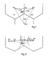
- a mobile station MS is currently in the radio cell belonging to the base station BS1, being at a distance d1M from this base station BS1 and at a distance d2M and d3M from the other two adjacent base stations BS2 and BS3.
- These distances d1 M, d2M and d3M change constantly when the mobile station MS is in motion.
- the mutual distances D12, D13 and D23 of the base stations BS1, BS2 and BS3 are invariable known quantities.
- the mobile station first orientates itself in the radio cell network by receiving organization signal channels sent from the base stations and comparing the received organization signal channels with regard to their signal qualities (field strength, signal-to-noise ratio), whereupon it reports to the base station, whose organization signal channel it has the best Quality.
- This signal quality measurement is an orientation aid for the mobile station, but due to the strong fluctuations in field strength in mobile radio, which are caused by shadowing and fading, this method is not suitable for making the radio cell boundaries recognizable precisely enough for the mobile station. This method of signal quality measurement is all the more unsuitable for detecting traffic-related shifts in radio cell boundaries.
- Each base station cyclically determines the offset times of its own TDMA frames compared to the corresponding TDMA frames of the surrounding neighboring base stations.
- a test receiver e.g. in the base station BS1 the time interval tB12 (see line 2)) between the start of its frame R1 and the time TB12 of the arrival of a signal sent by the neighboring base station BS2, which identifies the start of the frame R1 of the base station BS2, was measured.
- This time interval tB12 reduced by the constant signal transit time t12 existing between the two base stations BS1 and BS2, results in the frame offset time tRV12 (see line 3)). Just like that.
- Lines 2) and 5) show that the frame offset time tRV13 in the base station B1 compared to another neighboring base station BS3 is determined from the time interval tB13 and the signal transit time t13.
- Lines 7) and 8) show the time interval tB21, the signal transit time t21 and the frame offset time tRV21, which were measured in the base station BS2 compared to the base station BS1.
- the frame offset time between two base stations can also be determined using any other frame than the one used in the exemplary embodiment.
- the signal delays t12, t13, t21 also take into account delay delays which are caused in the transmitters and receivers of the base stations.
- Each base station should re-determine the frame offset time with respect to each of its neighboring base stations approximately every 2 minutes, so that with a frequency accuracy in the mobile radio network of 10 -9, the mobile stations can determine their distances from the base stations with an accuracy of ⁇ 100 m.
- a mobile station MS e.g. has reported to base station BS1 on the basis of the most favorable reception conditions, it receives the frame offset time tRV12, which base station BS1 has determined with respect to neighboring base station BS2, in the organization signal channel.
- the time interval tM1 (see line 11)) between the start of its frame R1 and the time TM1 of the arrival of a signal transmitted by the base station BS1, which characterizes the start of the frame R1 in this base station BS1, is measured in the mobile station MS.
- the time interval tM2 (see line 11)) between the start of its frame R2 and the time TM2 of the arrival of a signal sent by the other base station BS2 is measured, which characterizes the start of the frame R2 in the base station BS2 .
- the mobile station must set its reception frequency to the transmission frequency of the base station from which it is to receive a signal.
- This signal delay difference is corrected so that circuit-related delay delays of the transmitters and receivers in the base stations and the mobile station are not included.
- the determination of the signal transit time difference At21 is explained with reference to lines 14) and 15) of FIG. 2 if BS2 is the reference base station for the mobile station.
- the signal transit time difference At21 then results from the time intervals tM1 and tM2 with respect to the base stations BS1 and BS2 and the frame offset time tRV21 of the base station BS2 with respect to the base station BS1.
- At21 tM1 - (tM2 + tRV21)
- the sum of the time interval tM2 and the frame offset time tRV21 is greater than a frame duration tR.
- the frame duration tR must first be subtracted from the sum of the time interval tM2 and the frame saturation time tRV21 before the difference is formed against the time interval tM1.
- the border between two neighboring radio cells was in the middle between their associated base stations.
- the actual transit time difference would assign the mobile station to an incorrect radio cell.
- a location at which a mobile station determines a difference in the actual transit times of zero would no longer lie on the radio cell boundary.
- the mobile station is therefore informed by the fixed stations, whose radio cell limit is to be shifted, of a correction value of the actual signal transit times, which changes the signal transit time difference in accordance with the shift of the radio cell boundary.
- This new signal delay difference .DELTA.t12 '(see line 13) in Fig. 2) causes the mobile station to exclude its radio connection to the base station BS2, although it is closer to the base station BS1.
- the new cell boundary between the base stations BS1 and BS2 is now in the middle between the first base station BS1 and a second fictitious base station BS2 '.
- the new cell boundary is shown as being in the middle between the base station BS2 and a fictitious base station BS1 ', which is a distance 2 ⁇ s further away from the base station BS2 than the actual base station BS1.
Abstract
Description
Die vorliegende Erfindung betrifft ein Verfahren -zum Ermitteln derjenigen Funkzelle eines zellularen Mobilfunknetzes, mit deren zugehöriger Feststation eine Mobitstation in Funkverbindung treten soll, wobei von der Mobilstation Laufzeitmessungen an Signalen ausgeführt werden, welche die Feststationen umliegender Funkzellen aussenden, dann von der Mobilstation die Differenze gebildet wird zwischen den Signalloaufzeiten von jeweils zwei benachbarten Feststationen zur Mobilstation und je nach dem Vorzeichen der Signallaufzeitdifferenz die Mobilstation entweder mit der einen oder der anderen Feststation in Verbindung gebracht wird und wobei im Falle einer Funkzellenvergrößerung bzw. -verkleine-rung der Mobilstation ein Korrekturwert für die Signaltaufzeiten von den Festslationen, deren zugehörige Funkzellengrenze verschoben werden soll, mitgeteilt wird, der proportional der Verschiebung der Funkzellengrenze ist.The present invention relates to a method for determining the radio cell of a cellular mobile radio network with the associated base station of which a mobile station is to establish a radio connection, the mobile station carrying out runtime measurements on signals which the base stations of surrounding radio cells emit, and then the difference is formed by the mobile station between the signal runtimes of two neighboring base stations to the mobile station and depending on the sign of the signal runtime difference, the mobile station is either connected to one or the other base station and, in the event of a cell enlargement or reduction of the mobile station, a correction value for the Signal propagation times from the fixed stations whose associated radio cell boundary is to be shifted, which is proportional to the shift of the radio cell boundary.
Ein derartiges Verfahren ist aus der "Funkschau", Jan. 1986, S. 2-7 und aus den "NTG-Fachberichten", Bewegliche Funkdienste, Bd. 90, Nov. 1985, S. 157-171 bekannt. Für das in diesen Druckschriften beschriebene Verfahren ist Voraussetzung, daß das Mobilfunknetz synchron arbeitet, d.h. daß alle Feststationen ihre Signale gleichphasig aussenden. Von den Mobiistationen können die Signale der Basisstationen somit mit gleichem Zeitbezug empfangen werden. Eine solche Netzsynchronisierung ist aber recht aufwendig, insbesondere dann, wenn das Mobilfunknetz länderübergreifend ausgedehnt werden soll.Such a method is known from the "Funkschau", Jan. 1986, pp. 2-7 and from the "NTG Technical Reports", Flexible Radio Services, Vol. 90, Nov. 1985, pp. 157-171. For the method described in these documents, it is a prerequisite that the mobile radio network works synchronously, i.e. that all base stations send their signals in phase. The signals from the base stations can thus be received by the mobile stations with the same time reference. Such a network synchronization is quite complex, especially when the mobile network is to be expanded across countries.
Der Erfindung liegt nun die Aufgabe zugrunde, ein Verfahren der eingangs genannten Art anzugeben, das es einer jeden Mobilstation auf einfache Weise ermöglicht, in einem asynchro nen und mit variablen Funkzellgrößen arbeitenden Mobilfunknetz jeweils die Funkzelle ihres Aufenthaitortes zu ermitteln, mit deren zugehöriger Feststation sie dann in Funkverbindung tritt.The invention is based on the object of specifying a method of the type mentioned, which enables each mobile station in a simple manner to determine the radio cell of their location in an asynchronous and working with variable radio cell sizes, with the associated base station of which they then starts radio communication.
Erfindungsgemäß wird diese Aufgabe durch die im Kennzeichen des Patentanspruchs 1 angegebenen Merkmale gelöstAccording to the invention, this object is achieved by the features specified in the characterizing part of
Zweckmäßige Ausführungen der Erfindung gehen aus den Unteransprüchen hervor.Appropriate embodiments of the invention emerge from the subclaims.
Anhand eines in der Zeichnung dargestellten Ausführungsbeispiels soll nachfolgend die Erfindung näher erläutert werden.
- Fig. 1- zeigt einen Ausschnitt einer Funkzeilenstruktur,
- Fig. 2 zeigt die zeitlichen Zusammenhänge des erfindungsgemäßen Verfahrens und
- Fig. 3 zeigt zwei benachbarte Funkzellen mit verschobener Zellgrenze.
- 1- shows a section of a radio line structure,
- 2 shows the temporal relationships of the method and
- 3 shows two adjacent radio cells with a shifted cell boundary.
In einem zellularen Mobilfunknetz sind den sich darin zunächst noch ohne Funkverbindung bewegenden Mobilstationen Kriterien zur Orientierung an die Hand zugeben, damit sie die für eine Funkverbindung in Frage kommende Feststation, in deren Funkzelle sie sich gerade aufhalten, finden. Außerdem benötigen die Mobilstationen, wenn sie eine Funkzelle verlassen und in eine andere überwechseln, Informationen darüber, in welche neue Funkzelle sie hineingelangen, auf deren Feststation sie sich dann umzuschalten haben. Diesen Vorgang bezeichnet man auch als Roaming. Um die genannten Vorgänge ausführen zu können, benötigen die Mobilstationen in gewissen Zeitabständen immer wieder Informationen über ihre Entfernungen von den in ihrer Umgebung befindlichen FeststationenIn a cellular mobile radio network, the mobile stations that are initially still moving without a radio connection are given criteria for orientation so that they can find the base station in question for a radio connection in whose radio cell they are currently located. In addition, when they leave one radio cell and switch to another, the mobile stations need information about which new radio cell they are entering and on whose base station they then have to switch. This process is also known as roaming. In order to be able to carry out the above-mentioned processes, the mobile stations repeatedly need information about their distances from the fixed stations in their vicinity at certain time intervals
Die Fig. 1 zeigt beispielsweise drei Funkzellen mit ihren Feststationen BS1, BS2 und BS3, auch Basisstationen genannt. Eine Mobilstation MS befindet sich augenblicklich in der zur Feststation BS1 gehörenden Funkzelle, wobei sie zu dieser Feststation BS1 den Abstand d1 M und zu den anderen beiden benachbarten Feststationen BS2 und BS3 die Abstände d2M und d3M hat. Diese Abstände d1 M, d2M und d3M ändern sich ständig, wenn die Mobilstation MS in Bewegung ist. Dagegen sind die gegenseitigen Abstände D12, D13 und D23 der Feststationen BS1, BS2 und BS3 unveränderliche bekannte Größen.1 shows, for example, three radio cells with their base stations BS1, BS2 and BS3, also called base stations. A mobile station MS is currently in the radio cell belonging to the base station BS1, being at a distance d1M from this base station BS1 and at a distance d2M and d3M from the other two adjacent base stations BS2 and BS3. These distances d1 M, d2M and d3M change constantly when the mobile station MS is in motion. In contrast, the mutual distances D12, D13 and D23 of the base stations BS1, BS2 and BS3 are invariable known quantities.
Die Mobilstation orientiert sich zunächst dadurch im Funkzellennetz, daß sie von den Feststationen ausgesendete Organisationssignalkanäle empfängt und die empfangenen Organisationssignalkanäle bezüglich ihrer Signalqualitäten (Feldstärke, Signal-zu -Geräuschverhältnis) miteinander vergleicht, worauf sie sich bei der Feststation meldet, deren Organisationssginalkanal sie mit der besten Qualität empfangen hat. Diese Signalqualitätsmessung stellt zwar eine Orientierungshilfe für die Mobilstation dar, aber auf Grund der im Mobilfunk vorkommenden starken Feldstärkeschwankungen, die durch Abschattungen und Fadings verursacht werden, ist diese Methode nicht geeignet, die Funkzellgrenzen genau genug für die Mobilstation erkennbar zu machen. Erst recht ist diese Methode der Signalqualitätsmessung allein nicht geeignet, verkehrsbedingte Verschiebungen von Funkzellengrenzen zu detektieren.The mobile station first orientates itself in the radio cell network by receiving organization signal channels sent from the base stations and comparing the received organization signal channels with regard to their signal qualities (field strength, signal-to-noise ratio), whereupon it reports to the base station, whose organization signal channel it has the best Quality. This signal quality measurement is an orientation aid for the mobile station, but due to the strong fluctuations in field strength in mobile radio, which are caused by shadowing and fading, this method is not suitable for making the radio cell boundaries recognizable precisely enough for the mobile station. This method of signal quality measurement is all the more unsuitable for detecting traffic-related shifts in radio cell boundaries.
Erst durch das nachfolgend beschriebene Verfahren der Signallaufzeitmessung ist eine Mobilstation in der Lage, recht genau zu ermitteln, in welcher Funkzelle sie sich augenblicklich befindet.Only through the method of signal propagation time measurement described below is a mobile station able to determine quite precisely which radio cell it is in at the moment.
Bei dem hier zugrundeliegenden Mobilfunksystem benutzen alle Feststationen und Mobilstationen für das Aussenden und Empfangen von Signalen die gleiche Zeitmultiplex (TDMA)-Rahmen struktur, und alle TDMA-Rahmen besitzen die gleiche Länge. Allerdings können die Rahmen in den Feststationen und Mobilstationen zeitlich gegeneinander versetzt sein, weil das Mobilfunknetz nicht synchronisiert ist. In den Zeilen 1), 6) und 10) der Fig. 2 ist beispielhaft dargestellt, wie die Rahmen R1 und die Rahmen R2 der zwei Feststationen BS1, BS2 und der Mobilstation zeitlich gegeneinander verschoben sind.In the mobile radio system on which this is based, all base stations and mobile stations use the same time division multiplex (TDMA) frame structure for transmitting and receiving signals, and all TDMA frames have the same length. However, the frames in the base stations and mobile stations can be offset from one another in time because the mobile radio network is not synchronized. Lines 1), 6) and 10) of FIG. 2 show, by way of example, how frames R1 and frames R2 of the two base stations BS1, BS2 and the mobile station are shifted in time from one another.
Von jeder Feststation werden zyklisch die Versatzzeiten der eigenen TDMA-Rahmen gegenüber den entsprechenden TDMA-Rahmen der umliegenden benachbarten Feststationen ermittelt. Dazu wird, wie im Zeitdiagramm der Fig. 2 dargestellt, von einem Meßempfägner z.B. in der Feststation BS1 der Zeitabstand tB12 (s. Zeile 2)) zwischen dem Beginn ihres Rahmens R1 und dem Zeitpunkt TB12 des Eintreffens eines von der Nachbarfeststation BS2 ausgesendeten Signals, welches den Beginn des Rahmens R1 der Feststation BS2 kennzeichnet, gemessen. Dieser Zeitabstand tB12, vermindert um die zwischen beiden Feststationen BS1 und BS2 bestehende konstante Signallaufzeit t12, ergibt die Rahmenversatzzeit tRV12 (s. Zeile 3)). Genauso wird, wie den. Zeilen 2) und 5) zu entnehmen ist, in der Feststation B1 die Rahmenversatzzeit tRV13 gegenüber einer anderen Nachbarfeststafion BS3 aus dem Zeitabstand tB13 und der Signallaufzeit t13 ermittelt. In den Zeilen 7) und 8) sind der Zeitabstand tB21, die Signallaufzeit t21 und die Rahmenversatzzeit tRV21 angegeben, welche in der Feststation BS2 gegenüber der Feststation BS1 gemessen worden sind.Each base station cyclically determines the offset times of its own TDMA frames compared to the corresponding TDMA frames of the surrounding neighboring base stations. For this purpose, as shown in the time diagram of Fig. 2, a test receiver e.g. in the base station BS1 the time interval tB12 (see line 2)) between the start of its frame R1 and the time TB12 of the arrival of a signal sent by the neighboring base station BS2, which identifies the start of the frame R1 of the base station BS2, was measured. This time interval tB12, reduced by the constant signal transit time t12 existing between the two base stations BS1 and BS2, results in the frame offset time tRV12 (see line 3)). Just like that. Lines 2) and 5) show that the frame offset time tRV13 in the base station B1 compared to another neighboring base station BS3 is determined from the time interval tB13 and the signal transit time t13. Lines 7) and 8) show the time interval tB21, the signal transit time t21 and the frame offset time tRV21, which were measured in the base station BS2 compared to the base station BS1.
Wegen der gleichen Rahmenstruktur in allen Feststationen läßt sich die Rahmenversatzzeit zwischen zwei Feststationen auch an Hand beliebiger anderer als der in dem Ausführungsbeispiel herangezogenen Rahmen bestimmen.Because of the same frame structure in all base stations, the frame offset time between two base stations can also be determined using any other frame than the one used in the exemplary embodiment.
Bei den Signallaufzeiten t12, t13, t21 sind auch Laufzeitverzögerungen berücksichtigt, welche in den Sendern und Empfängern der Feststationen verursacht werden.The signal delays t12, t13, t21 also take into account delay delays which are caused in the transmitters and receivers of the base stations.
Jede Feststation sollte die Rahmenversatzzeit gegenüber jeder seiner benachbarten Feststationen etwa alle 2 Minuten neu ermitteln, so daß bei einer Frequenzgenauigkeit im Mobilfunknetz von 10-9 die Mobilstationen ihre Abstände von den Feststationen auf ± 100 m genau bestimmen können.Each base station should re-determine the frame offset time with respect to each of its neighboring base stations approximately every 2 minutes, so that with a frequency accuracy in the mobile radio network of 10 -9, the mobile stations can determine their distances from the base stations with an accuracy of ± 100 m.
Eine Mobilstation MS, die sich z.B. auf Grund der günstigsten Empfangsbedingungen bei der Feststation BS1 gemeldet hat, bekommt im Organisationssignalkanal von dieser die Rahmenversatzzeit tRV12, welche die Feststation BS1 gegenüber der Nachbarfeststation BS2 ermittelt hat, mitgeteilt. Zudem wird in der Mobilstation MS der Zeitabstand tM1 (s. Zeile 11)) zwischen dem Beginn ihres Rahmens R1 und dem Zeitpunkt TM1 des Eintreffens eines von der Feststation BS1 ausgesendeten Signals, welches den Beginn des Rahmens R1 in dieser Feststation BS1 kennzeichnet, gemessen. Und ebenso wird in der Mobilstation MS der Zeitabstand tM2 (s. Zeile 11)) zwischen dem Beginn ihres Rahmens R2 und dem Zeitpunkt TM2 des Eintreffens eines von der anderen Feststation BS2 ausgesendeten Signals gemessen, welches den Beginn des Rahmens R2 in der Feststation BS2 kennzeichnet. Die Mobilstation hat ihre Empfangsfrequenz jeweils auf die Sendefrequenz derjenigen Feststation einzustellen, von der sie ein Signal empfangen soll.A mobile station MS, e.g. has reported to base station BS1 on the basis of the most favorable reception conditions, it receives the frame offset time tRV12, which base station BS1 has determined with respect to neighboring base station BS2, in the organization signal channel. In addition, the time interval tM1 (see line 11)) between the start of its frame R1 and the time TM1 of the arrival of a signal transmitted by the base station BS1, which characterizes the start of the frame R1 in this base station BS1, is measured in the mobile station MS. And also in the mobile station MS the time interval tM2 (see line 11)) between the start of its frame R2 and the time TM2 of the arrival of a signal sent by the other base station BS2 is measured, which characterizes the start of the frame R2 in the base station BS2 . The mobile station must set its reception frequency to the transmission frequency of the base station from which it is to receive a signal.
Um herauszufinden, welcher von beiden Feststationen BS1 und BS2 die Mobilstation näher lokalisiert ist, wird in der Mobilstation die Differenz zwischen der Signallaufzeit von der einen Feststation BS1 bis zu ihr und der Signallaufzeit von der anderen Feststation BS2 bis zu ihr auf folgende Weise bestimmt:
- Die Signallaufzeit t12 ergibt sich, wie den Zeilen 11) und 12) der Fig. 2 zu entnehmen ist, dadurch, daß in der Mobilstation MS die Differenz gebildet wird zwischen dem Zeit abstand tM2 gegenüber der Feststation BS2 und dem Zeitabstand tM1 gegenüber der Feststation BS1 zuzüglich der Rahmenversatzzeit tRV12 der Feststation BS1 gegenüber der Feststation BS2. Δt12 = tM2 - (tM1 + tRV12)
- The signal transit time t12 results, as can be seen from lines 11) and 12) of FIG. 2, in that the difference is formed in the mobile station MS between the time interval tM2 with respect to the base station BS2 and the time interval tM1 with respect to the base station BS1 plus the frame offset time tRV12 of the base station BS1 compared to the base station BS2. Δt12 = tM2 - (tM1 + tRV12)
Diese Signallaufzeitdifferenz ist so korrigiert, daß darin schaltungsbedingte Laufzeitverzögerungen der Sender und Empfänger in den Feststationen und der Mobilstation nicht eingehen.This signal delay difference is corrected so that circuit-related delay delays of the transmitters and receivers in the base stations and the mobile station are not included.
Stellt sich für die Signallaufzeitdifferenz ein Wert At12 > 0 ein, so befindet sich die Mobilstation näher bei der Feststation BS1, und für eine Signallaufzeitdifferenz At12 <0 befindet sie sich näher bei der anderen Feststation BS2. Bei einer Signallaufzeitdifferenz At12 = 0 befindet sich die Mobilstation genau auf der Funkzellengrenze zwischen den beiden benachbarten Feststationen BS1 und BS2.If a value At12> 0 is set for the signal transit time difference, the mobile station is closer to the base station BS1, and for a signal transit time difference At12 <0 it is closer to the other base station BS2. With a signal delay difference At12 = 0, the mobile station is located exactly on the radio cell boundary between the two neighboring base stations BS1 and BS2.
Während bei der oben beschriebenen Bestimmung der Signallaufzeitdifferenz At12 die Feststation BS1 als Bezug für die Mobilstation galt, sei an Hand der Zeilen 14) und 15) der Fig. 2 die Bestimmung der Signallaufzeitdifferenz At21 erläutert, wenn BS2 die Bezugsfeststation für die Mobilstafion ist. Die Signallaufzeitdifferenz At21 ergibt sich dann aus den Zeitabständen tM1 und tM2 gegenüber den Feststationen BS1 und BS2 und der Rahmenversatzzeit tRV21 der Feststation BS2 gegenüber der Feststation BS1. At21 = tM1 - (tM2 + tRV21)While in the above-described determination of the signal transit time difference At12 the base station BS1 was regarded as the reference for the mobile station, the determination of the signal transit time difference At21 is explained with reference to lines 14) and 15) of FIG. 2 if BS2 is the reference base station for the mobile station. The signal transit time difference At21 then results from the time intervals tM1 and tM2 with respect to the base stations BS1 and BS2 and the frame offset time tRV21 of the base station BS2 with respect to the base station BS1. At21 = tM1 - (tM2 + tRV21)
Beim in den Zeilen 14) und 15) der Fig. 2 dargestellten Beispiel ist die Summe des Zeitabstandes tM2 und der Rahmenversatzzeit tRV21 größer als eine Rahmendauer tR. In einem solchen Fall muß zunächst von der Summe des Zeitabstandes tM2 und der Rahmenversattzeit tRV21 die Rahmendauer tR abgezogen werden, bevor die Differenz gegen den Zeitabstand tM1 gebildet wird.In the example shown in lines 14) and 15) of FIG. 2, the sum of the time interval tM2 and the frame offset time tRV21 is greater than a frame duration tR. In such a case, the frame duration tR must first be subtracted from the sum of the time interval tM2 and the frame saturation time tRV21 before the difference is formed against the time interval tM1.
Das vorangehend geschilderte Verfahren, nach dem jeweils von zwei Feststationen diejenige bestimmt wird, zu der die Mobilstation der geringeren Abstand aufweist, wird nun mit all den Feststationen durchgeführt deren Signale die Mobilstation mit ausreichend guter Qualität empfängt, bis diejenige Feststation gefunden worden ist, zu der die Mobilstation die geringste Entfernung hat.The above-described method, according to which the base station is determined by two base stations, is now carried out with all base stations whose signals the base station receives with sufficiently good quality until the base station to which it is found has been found the mobile station is the shortest distance.
Im dem bisher betrachteten Fall verlief die Grenze jeweils zweier benachbarter Funkzellen mitten zwischen deren zugehörigen Basisstationen. Oft ist es aber zweckmäßig, je nach dem Verkehrsaufkommen Funkzellen zu vergrößern oder zu verkleinem; d.h. die Funkzellengrenze zwischen zwei benachbarten Feststationen wird näher zur einen Feststation hin und weiter von der anderen Feststation weggerückt. Bei einer Funkzellengrenzverschiebung würde die wirkliche Laufzeitdifferenz die Mobilstation einer falschen Funkzelle zuweisen. Denn bei einer Funkzellengrößenänderung würde ein Ort, an dem eine Mobilstation eine Differenz der tatsächlichen, Laufzeiten von Null ermittelt nicht mehr auf der Funkzellengrenze liegen. Es wird daher der Mobilstation von den Feststationen, deren Funkzellengrenze verschoben werden soll, ein Korrekturwert der tatsächlichen Signallaufzeiten mitgeteilt, welcher die Signallaufzeitdifferenz entsprechend der Verschiebung der Funkzellengrenze verändert.In the case considered so far, the border between two neighboring radio cells was in the middle between their associated base stations. However, it is often advisable to enlarge or reduce radio cells depending on the traffic volume; i.e. the radio cell boundary between two neighboring base stations is moved closer to one base station and further away from the other base station. In the event of a cell boundary shift, the actual transit time difference would assign the mobile station to an incorrect radio cell. In the event of a change in radio cell size, a location at which a mobile station determines a difference in the actual transit times of zero would no longer lie on the radio cell boundary. The mobile station is therefore informed by the fixed stations, whose radio cell limit is to be shifted, of a correction value of the actual signal transit times, which changes the signal transit time difference in accordance with the shift of the radio cell boundary.
Wenn beispielsweise, wie in Fig. 3 dargestellt, die Grenze der Funkzellen der beiden benachbarten Feststationen BS1 und BS2 in Richtung auf die Feststationen BS1 um die Strecke s verschoben werden soll, dann wird von der Feststation BS1 die tatsächlich ermittelte Rahmenversatzzeit tRV12 um den Zeitbetrag tk = 2Δs/V (V![]()
![]()
In der Feststation BS1 wird die um tk = 2Δs/V vergrößerte Rahmenversatzzeit tRV12' dadurch gebildet, daß der gemessene Zeitabstand tB12 nicht um die bekannte Signallaufzeit t12, sondem um die Signallaufzeit t12' = t12 - tk (s. Zeilen 2) und 4) in Fig. 2) vermindert wird.In the base station BS1, the frame offset time tRV12 'increased by t k = 2Δs / V is formed by the fact that the measured time interval tB12 is not by the known signal transit time t12, but by the signal transit time t12' = t12 - t k (see lines 2) and 4) is reduced in Fig. 2).
Wie aus der Fig. 3 ersichtlich, liegt nämlich die neue Zellgrenze zwischen den Feststationen BS1 und BS2 nun in der Mitte zwischen der ersten Feststation BS1 und einer zweiten fiktiven Feststation BS2'. Die fiktive Feststation BS2' ist dabei um eine Strecke 2Δs näher als die wirkliche Feststation BS2 an die Feststation BS1 herangerückt. Daher ist auch die fiktive Laufzeit t12' um die Zeit tK = 2Δs/V kürzer als die wirkliche Laufzeit t12, die durch die festliegende bekannte Entfernung zwischen den beiden Feststationen BS1 und BS2 gegeben ist.As can be seen from FIG. 3, the new cell boundary between the base stations BS1 and BS2 is now in the middle between the first base station BS1 and a second fictitious base station BS2 '. The fictitious base station BS2 'is closer to the base station BS1 by a distance 2Δs than the actual base station BS2. Therefore, the fictitious transit time t12 'by the time t K = 2Δs / V is shorter than the actual transit time t12, which is given by the known distance between the two base stations BS1 and BS2.
Umgekehrt stellt sich von der Feststation BS2 aus gesehen die neue Zellgranze als in der Mitte zwischen der Feststation BS2 und einer fiktiven Feststation BS1' dar, die um eine Strecke 2Δs weiter als die wirkliche Feststation BS1 von der Feststation BS2 entfernt liegt. Daher ist die fiktive Laufzeit t12' um die Zeit tk = 2Δs/V länger als die wirkliche Laufzeit t12.Conversely, seen from the base station BS2, the new cell boundary is shown as being in the middle between the base station BS2 and a fictitious base station BS1 ', which is a distance 2Δs further away from the base station BS2 than the actual base station BS1. The fictitious transit time t12 'is therefore longer than the actual transit time t12 by the time t k = 2Δs / V.
Wie von der Feststation BS2 aus gesehen eine Verschiebung der Funkzsllengrenze auf die benachbarte Feststation BS1 zu sich in der fiktiven Rahmenversatzzeit tRV21' ausdrückt und diese fiktive Rahmenversatzzeit tRV21' sich auf die Signallaufzeitdifferenz Δt21' auswirkt, zeigen die Zeilen 9) und 16) in der Fig. 2.As seen from the base station BS2, a shift of the radio cell limit to the adjacent base station BS1 towards itself in the fictitious frame offset time tRV21 'and this fictitious frame offset time tRV21' affects the signal transit time difference Δt21 'is shown in lines 9) and 16) in the figure . 2.
Claims (3)
Priority Applications (2)
| Application Number | Priority Date | Filing Date | Title |
|---|---|---|---|
| DE8686104975T DE3673642D1 (en) | 1986-04-11 | 1986-04-11 | METHOD FOR DETERMINING THE STAY RADIO CELL OF A MOBILE STATION WITHIN A MOBILE RADIO NETWORK. |
| EP19860104975 EP0241565B1 (en) | 1986-04-11 | 1986-04-11 | Method for determining the sojourn cell of a mobile station in a mobile radio network |
Applications Claiming Priority (1)
| Application Number | Priority Date | Filing Date | Title |
|---|---|---|---|
| EP19860104975 EP0241565B1 (en) | 1986-04-11 | 1986-04-11 | Method for determining the sojourn cell of a mobile station in a mobile radio network |
Publications (2)
| Publication Number | Publication Date |
|---|---|
| EP0241565A1 true EP0241565A1 (en) | 1987-10-21 |
| EP0241565B1 EP0241565B1 (en) | 1990-08-22 |
Family
ID=8195053
Family Applications (1)
| Application Number | Title | Priority Date | Filing Date |
|---|---|---|---|
| EP19860104975 Expired - Lifetime EP0241565B1 (en) | 1986-04-11 | 1986-04-11 | Method for determining the sojourn cell of a mobile station in a mobile radio network |
Country Status (2)
| Country | Link |
|---|---|
| EP (1) | EP0241565B1 (en) |
| DE (1) | DE3673642D1 (en) |
Cited By (11)
| Publication number | Priority date | Publication date | Assignee | Title |
|---|---|---|---|---|
| EP0335558A2 (en) * | 1988-03-26 | 1989-10-04 | The Marconi Company Limited | Radio communication system |
| FR2646302A1 (en) * | 1989-04-25 | 1990-10-26 | Matra Communication | PSEUDO-SYNCHRONIZATION METHOD OF A TIME-MULTIPLEXED COMMUNICATION NETWORK AND APPLICATIONS |
| EP0593320A1 (en) * | 1992-09-15 | 1994-04-20 | Alcatel Mobile Communication France | Transmission method of time advance information to a mobile moving in a cellular radio telephone network, mobile, controller and information exchange system using this method |
| WO1996035306A1 (en) * | 1995-05-02 | 1996-11-07 | Telecom Securicor Cellular Radio Limited | Cellular radio location system |
| GB2305823A (en) * | 1995-09-30 | 1997-04-16 | Rural Radio Systems Ltd | Distributed circuit switched telecommunication network |
| WO1997016893A1 (en) * | 1995-10-30 | 1997-05-09 | Vlsi Technology, Inc. | Timing system for mobile cellular radio receivers |
| EP0800319A1 (en) * | 1996-04-02 | 1997-10-08 | Hewlett-Packard Company | Locating method for mobile radio systems |
| GB2316823A (en) * | 1996-08-24 | 1998-03-04 | Motorola Ltd | Loxcating cellular radio transmitter |
| WO1999041854A1 (en) * | 1998-02-12 | 1999-08-19 | Telefonaktiebolaget Lm Ericsson (Publ) | Method and system for facilitating timing of base stations in an asynchronous cdma mobile communications system |
| US6456237B1 (en) | 1998-03-31 | 2002-09-24 | Nokia Networks Oy | Method of measuring time difference, and radio system |
| EP1737144A2 (en) * | 1998-02-12 | 2006-12-27 | Telefonaktiebolaget LM Ericsson (publ) | Method and system for facilitating timing of base stations in an asynchronous CDMA mobile communications system |
Families Citing this family (1)
| Publication number | Priority date | Publication date | Assignee | Title |
|---|---|---|---|---|
| US6560461B1 (en) | 1997-08-04 | 2003-05-06 | Mundi Fomukong | Authorized location reporting paging system |
Citations (3)
| Publication number | Priority date | Publication date | Assignee | Title |
|---|---|---|---|---|
| GB2017448A (en) * | 1978-03-25 | 1979-10-03 | Messerschmitt Boelkow Blohm | Method of flight guidance |
| DE3242997A1 (en) * | 1982-11-20 | 1984-05-24 | Standard Elektrik Lorenz Ag, 7000 Stuttgart | Position indicating system |
| DE3335128A1 (en) * | 1983-09-28 | 1985-04-11 | Siemens AG, 1000 Berlin und 8000 München | MOBILE RADIO NETWORK |
-
1986
- 1986-04-11 EP EP19860104975 patent/EP0241565B1/en not_active Expired - Lifetime
- 1986-04-11 DE DE8686104975T patent/DE3673642D1/en not_active Expired - Lifetime
Patent Citations (3)
| Publication number | Priority date | Publication date | Assignee | Title |
|---|---|---|---|---|
| GB2017448A (en) * | 1978-03-25 | 1979-10-03 | Messerschmitt Boelkow Blohm | Method of flight guidance |
| DE3242997A1 (en) * | 1982-11-20 | 1984-05-24 | Standard Elektrik Lorenz Ag, 7000 Stuttgart | Position indicating system |
| DE3335128A1 (en) * | 1983-09-28 | 1985-04-11 | Siemens AG, 1000 Berlin und 8000 München | MOBILE RADIO NETWORK |
Non-Patent Citations (2)
| Title |
|---|
| FUNKSCHAU, Band 2, 17. Januar 1986, Seiten 43-48, München, DE; G.-L. RADKE: "Das neue Funk-Telefonnetz "C": Digital signalisiert" * |
| IEEE TRANSACTIONS ON VEHICULAR TECHNOLOGY, Band VT-26, Nr. 1, Februar 1977, Seiten 7-11, New York, US; S. RITER et al.: "Automatic vehicle location - An overview" * |
Cited By (26)
| Publication number | Priority date | Publication date | Assignee | Title |
|---|---|---|---|---|
| EP0335558A2 (en) * | 1988-03-26 | 1989-10-04 | The Marconi Company Limited | Radio communication system |
| EP0335558A3 (en) * | 1988-03-26 | 1991-03-20 | The Marconi Company Limited | Radio communication system |
| FR2646302A1 (en) * | 1989-04-25 | 1990-10-26 | Matra Communication | PSEUDO-SYNCHRONIZATION METHOD OF A TIME-MULTIPLEXED COMMUNICATION NETWORK AND APPLICATIONS |
| EP0398773A1 (en) * | 1989-04-25 | 1990-11-22 | Matra Communication | Pseudosynchronisation-method for a time division multiplexed communication network and use of same |
| US5128925A (en) * | 1989-04-25 | 1992-07-07 | Matra Communication | Process for the pseudo-synchronization of a time multiplexing communication network and uses thereof |
| EP0593320A1 (en) * | 1992-09-15 | 1994-04-20 | Alcatel Mobile Communication France | Transmission method of time advance information to a mobile moving in a cellular radio telephone network, mobile, controller and information exchange system using this method |
| AU701275B2 (en) * | 1995-05-02 | 1999-01-21 | Bt Cellnet Limited | Cellular radio location system |
| US6201803B1 (en) | 1995-05-02 | 2001-03-13 | British Telecommunications Public Limited Company | Cellular radio location system |
| WO1996035306A1 (en) * | 1995-05-02 | 1996-11-07 | Telecom Securicor Cellular Radio Limited | Cellular radio location system |
| CN1629654B (en) * | 1995-05-02 | 2010-05-26 | O2控股有限公司 | Cellular radio location system |
| GB2305823A (en) * | 1995-09-30 | 1997-04-16 | Rural Radio Systems Ltd | Distributed circuit switched telecommunication network |
| GB2305823B (en) * | 1995-09-30 | 2000-06-28 | Rural Radio Systems Ltd | Distributed circuit switched telecommunications networks |
| WO1997016893A1 (en) * | 1995-10-30 | 1997-05-09 | Vlsi Technology, Inc. | Timing system for mobile cellular radio receivers |
| US5694392A (en) * | 1995-10-30 | 1997-12-02 | Vlsi Technology, Inc. | Timing system for mobile cellular radio receivers |
| EP0800319A1 (en) * | 1996-04-02 | 1997-10-08 | Hewlett-Packard Company | Locating method for mobile radio systems |
| US6061565A (en) * | 1996-04-02 | 2000-05-09 | Hewlett-Packard Company | Mobile radio systems |
| GB2316823A (en) * | 1996-08-24 | 1998-03-04 | Motorola Ltd | Loxcating cellular radio transmitter |
| US6526039B1 (en) | 1998-02-12 | 2003-02-25 | Telefonaktiebolaget Lm Ericsson | Method and system for facilitating timing of base stations in an asynchronous CDMA mobile communications system |
| AU761795B2 (en) * | 1998-02-12 | 2003-06-12 | Telefonaktiebolaget Lm Ericsson (Publ) | Method and system for facilitating timing of base stations in an asynchronous CDMA mobile communications system |
| EP1737144A2 (en) * | 1998-02-12 | 2006-12-27 | Telefonaktiebolaget LM Ericsson (publ) | Method and system for facilitating timing of base stations in an asynchronous CDMA mobile communications system |
| EP1755239A2 (en) * | 1998-02-12 | 2007-02-21 | Telefonaktiebolaget LM Ericsson (publ) | Method and system for facilitating timing of base stations in an asynchronous CDMA mobile communications system |
| EP1755239A3 (en) * | 1998-02-12 | 2008-03-19 | Telefonaktiebolaget LM Ericsson (publ) | Method and system for facilitating timing of base stations in an asynchronous CDMA mobile communications system |
| EP1742386A3 (en) * | 1998-02-12 | 2008-03-19 | Telefonaktiebolaget LM Ericsson (publ) | Method and system for facilitating timing of base stations in an asynchronous CDMA mobile communications system |
| EP1737144A3 (en) * | 1998-02-12 | 2008-03-19 | Telefonaktiebolaget LM Ericsson (publ) | Method and system for facilitating timing of base stations in an asynchronous CDMA mobile communications system |
| WO1999041854A1 (en) * | 1998-02-12 | 1999-08-19 | Telefonaktiebolaget Lm Ericsson (Publ) | Method and system for facilitating timing of base stations in an asynchronous cdma mobile communications system |
| US6456237B1 (en) | 1998-03-31 | 2002-09-24 | Nokia Networks Oy | Method of measuring time difference, and radio system |
Also Published As
| Publication number | Publication date |
|---|---|
| EP0241565B1 (en) | 1990-08-22 |
| DE3673642D1 (en) | 1990-09-27 |
Similar Documents
| Publication | Publication Date | Title |
|---|---|---|
| EP0938821B1 (en) | Process and base station system for configuring an air interface between a mobile station and a base station in a time-division multiplex mobile radio telephone system for packet data transmission | |
| DE60206644T2 (en) | Variable speed feedback on channel quality in a wireless communication system | |
| EP0241565B1 (en) | Method for determining the sojourn cell of a mobile station in a mobile radio network | |
| DE60107066T2 (en) | SYNCHRONIZATION OF TIME SHIFT AND TIME DEVIATION | |
| DE69936753T2 (en) | METHOD FOR OPERATIONAL MONITORING OF A CELLULAR RADIO SYSTEM | |
| DE19681609B4 (en) | Apparatus and method for measuring signal strength in a wireless transmission system | |
| DE60034759T2 (en) | System and method for transmission power control | |
| DE2165019B2 (en) | Broadcast telecommunication system | |
| EP0412286B1 (en) | Route-selective reproduction method for digitally coded messages transmitted from a transmitter to a vehicle receiver, and corresponding vehicle receiver | |
| EP0833463B1 (en) | Method for action control in a time slot method | |
| EP0214319B1 (en) | Method for passing a mobile station from one radio station to another one | |
| WO2001043307A2 (en) | Method for maintaining a synchronised upward signal transmission in a radio communication system | |
| DE19647629C2 (en) | Method and base station system for configuring a radio interface between a mobile station and a base station of a time-division multiplex mobile radio system for packet data transmission | |
| EP3580932B1 (en) | Transmitter detection as vehicles drive through tunnel | |
| DE4319694C2 (en) | Methods for improving the radio coverage of mobile telephones in mobile radio systems | |
| DE60204530T2 (en) | Method for synchronizing a communication mobile terminal | |
| DE19851288C1 (en) | Signal transmission method for radio communication system using TDMA | |
| EP1238463B1 (en) | Method and system for transmitting data and for determining the transmission properties in a radio communications system | |
| DE3626059A1 (en) | Radio network | |
| DE1230471B (en) | FM communication system using equally modulated transmitters that use carrier frequencies in the same radio channel | |
| DE19622349C2 (en) | Method and provision of a control signal for the control of a radio receiver after a change of location | |
| EP1210779B1 (en) | Method for determining base stations able to communicate with a mobile station in a mobile radiotelephone system | |
| DE19737758A1 (en) | Method for setting the transmission carrier frequency in a subscriber station of a point-to-multipoint radio transmission system | |
| DE3002240C2 (en) | Traffic radio system | |
| EP0833461A1 (en) | Polarization diversity receiver unit for frame-based mobile communication systems |
Legal Events
| Date | Code | Title | Description |
|---|---|---|---|
| PUAI | Public reference made under article 153(3) epc to a published international application that has entered the european phase |
Free format text: ORIGINAL CODE: 0009012 |
|
| AK | Designated contracting states |
Kind code of ref document: A1 Designated state(s): DE FR GB IT NL SE |
|
| 17P | Request for examination filed |
Effective date: 19871106 |
|
| 17Q | First examination report despatched |
Effective date: 19891211 |
|
| GRAA | (expected) grant |
Free format text: ORIGINAL CODE: 0009210 |
|
| ITF | It: translation for a ep patent filed |
Owner name: BARZANO' E ZANARDO MILANO S.P.A. |
|
| AK | Designated contracting states |
Kind code of ref document: B1 Designated state(s): DE FR GB IT NL SE |
|
| REF | Corresponds to: |
Ref document number: 3673642 Country of ref document: DE Date of ref document: 19900927 |
|
| GBT | Gb: translation of ep patent filed (gb section 77(6)(a)/1977) | ||
| ET | Fr: translation filed | ||
| ITTA | It: last paid annual fee | ||
| PLBE | No opposition filed within time limit |
Free format text: ORIGINAL CODE: 0009261 |
|
| STAA | Information on the status of an ep patent application or granted ep patent |
Free format text: STATUS: NO OPPOSITION FILED WITHIN TIME LIMIT |
|
| 26N | No opposition filed | ||
| PGFP | Annual fee paid to national office [announced via postgrant information from national office to epo] |
Ref country code: NL Payment date: 19920430 Year of fee payment: 7 |
|
| REG | Reference to a national code |
Ref country code: GB Ref legal event code: 746 |
|
| PGFP | Annual fee paid to national office [announced via postgrant information from national office to epo] |
Ref country code: GB Payment date: 19930325 Year of fee payment: 8 |
|
| PGFP | Annual fee paid to national office [announced via postgrant information from national office to epo] |
Ref country code: FR Payment date: 19930416 Year of fee payment: 8 |
|
| REG | Reference to a national code |
Ref country code: FR Ref legal event code: DL |
|
| PG25 | Lapsed in a contracting state [announced via postgrant information from national office to epo] |
Ref country code: NL Effective date: 19931101 |
|
| NLV4 | Nl: lapsed or anulled due to non-payment of the annual fee | ||
| PG25 | Lapsed in a contracting state [announced via postgrant information from national office to epo] |
Ref country code: GB Effective date: 19940411 |
|
| PG25 | Lapsed in a contracting state [announced via postgrant information from national office to epo] |
Ref country code: SE Effective date: 19940412 |
|
| GBPC | Gb: european patent ceased through non-payment of renewal fee |
Effective date: 19940411 |
|
| PG25 | Lapsed in a contracting state [announced via postgrant information from national office to epo] |
Ref country code: FR Effective date: 19941229 |
|
| EUG | Se: european patent has lapsed |
Ref document number: 86104975.7 Effective date: 19941110 |
|
| REG | Reference to a national code |
Ref country code: FR Ref legal event code: ST |
|
| PGFP | Annual fee paid to national office [announced via postgrant information from national office to epo] |
Ref country code: SE Payment date: 19950425 Year of fee payment: 10 |
|
| PGFP | Annual fee paid to national office [announced via postgrant information from national office to epo] |
Ref country code: DE Payment date: 20020618 Year of fee payment: 17 |
|
| PG25 | Lapsed in a contracting state [announced via postgrant information from national office to epo] |
Ref country code: DE Free format text: LAPSE BECAUSE OF NON-PAYMENT OF DUE FEES Effective date: 20031101 |
|
| PG25 | Lapsed in a contracting state [announced via postgrant information from national office to epo] |
Ref country code: IT Free format text: LAPSE BECAUSE OF NON-PAYMENT OF DUE FEES;WARNING: LAPSES OF ITALIAN PATENTS WITH EFFECTIVE DATE BEFORE 2007 MAY HAVE OCCURRED AT ANY TIME BEFORE 2007. THE CORRECT EFFECTIVE DATE MAY BE DIFFERENT FROM THE ONE RECORDED. Effective date: 20050411 |