EP0240658B1 - Fluid proportioning pump system - Google Patents
Fluid proportioning pump system Download PDFInfo
- Publication number
- EP0240658B1 EP0240658B1 EP87101275A EP87101275A EP0240658B1 EP 0240658 B1 EP0240658 B1 EP 0240658B1 EP 87101275 A EP87101275 A EP 87101275A EP 87101275 A EP87101275 A EP 87101275A EP 0240658 B1 EP0240658 B1 EP 0240658B1
- Authority
- EP
- European Patent Office
- Prior art keywords
- fluid
- output
- intake
- chambers
- chamber
- Prior art date
- Legal status (The legal status is an assumption and is not a legal conclusion. Google has not performed a legal analysis and makes no representation as to the accuracy of the status listed.)
- Expired
Links
- 239000012530 fluid Substances 0.000 title claims description 35
- 239000007788 liquid Substances 0.000 claims description 54
- 238000006073 displacement reaction Methods 0.000 claims description 38
- 238000005086 pumping Methods 0.000 claims description 12
- 230000007423 decrease Effects 0.000 claims description 4
- 238000004811 liquid chromatography Methods 0.000 claims description 2
- 239000000203 mixture Substances 0.000 description 44
- 239000002904 solvent Substances 0.000 description 16
- 238000007599 discharging Methods 0.000 description 11
- 239000000523 sample Substances 0.000 description 10
- 230000003247 decreasing effect Effects 0.000 description 7
- 239000000470 constituent Substances 0.000 description 6
- 238000000926 separation method Methods 0.000 description 5
- 239000011324 bead Substances 0.000 description 2
- 239000007787 solid Substances 0.000 description 2
- 230000009286 beneficial effect Effects 0.000 description 1
- 238000004587 chromatography analysis Methods 0.000 description 1
- 230000009977 dual effect Effects 0.000 description 1
- 239000007789 gas Substances 0.000 description 1
- 238000009499 grossing Methods 0.000 description 1
- 238000002347 injection Methods 0.000 description 1
- 239000007924 injection Substances 0.000 description 1
- 238000000034 method Methods 0.000 description 1
- 238000004904 shortening Methods 0.000 description 1
- 239000002002 slurry Substances 0.000 description 1
- 239000000126 substance Substances 0.000 description 1
- 239000002699 waste material Substances 0.000 description 1
Images


Classifications
-
- G—PHYSICS
- G05—CONTROLLING; REGULATING
- G05D—SYSTEMS FOR CONTROLLING OR REGULATING NON-ELECTRIC VARIABLES
- G05D11/00—Control of flow ratio
- G05D11/02—Controlling ratio of two or more flows of fluid or fluent material
- G05D11/13—Controlling ratio of two or more flows of fluid or fluent material characterised by the use of electric means
- G05D11/131—Controlling ratio of two or more flows of fluid or fluent material characterised by the use of electric means by measuring the values related to the quantity of the individual components
- G05D11/132—Controlling ratio of two or more flows of fluid or fluent material characterised by the use of electric means by measuring the values related to the quantity of the individual components by controlling the flow of the individual components
-
- F—MECHANICAL ENGINEERING; LIGHTING; HEATING; WEAPONS; BLASTING
- F04—POSITIVE - DISPLACEMENT MACHINES FOR LIQUIDS; PUMPS FOR LIQUIDS OR ELASTIC FLUIDS
- F04B—POSITIVE-DISPLACEMENT MACHINES FOR LIQUIDS; PUMPS
- F04B13/00—Pumps specially modified to deliver fixed or variable measured quantities
- F04B13/02—Pumps specially modified to deliver fixed or variable measured quantities of two or more fluids at the same time
-
- F—MECHANICAL ENGINEERING; LIGHTING; HEATING; WEAPONS; BLASTING
- F04—POSITIVE - DISPLACEMENT MACHINES FOR LIQUIDS; PUMPS FOR LIQUIDS OR ELASTIC FLUIDS
- F04B—POSITIVE-DISPLACEMENT MACHINES FOR LIQUIDS; PUMPS
- F04B49/00—Control, e.g. of pump delivery, or pump pressure of, or safety measures for, machines, pumps, or pumping installations, not otherwise provided for, or of interest apart from, groups F04B1/00 - F04B47/00
- F04B49/06—Control using electricity
- F04B49/065—Control using electricity and making use of computers
-
- G—PHYSICS
- G05—CONTROLLING; REGULATING
- G05D—SYSTEMS FOR CONTROLLING OR REGULATING NON-ELECTRIC VARIABLES
- G05D11/00—Control of flow ratio
- G05D11/001—Control of flow ratio with discontinuous action
-
- G—PHYSICS
- G01—MEASURING; TESTING
- G01N—INVESTIGATING OR ANALYSING MATERIALS BY DETERMINING THEIR CHEMICAL OR PHYSICAL PROPERTIES
- G01N30/00—Investigating or analysing materials by separation into components using adsorption, absorption or similar phenomena or using ion-exchange, e.g. chromatography or field flow fractionation
- G01N30/02—Column chromatography
- G01N30/26—Conditioning of the fluid carrier; Flow patterns
- G01N30/28—Control of physical parameters of the fluid carrier
- G01N30/32—Control of physical parameters of the fluid carrier of pressure or speed
- G01N2030/324—Control of physical parameters of the fluid carrier of pressure or speed speed, flow rate
-
- G—PHYSICS
- G01—MEASURING; TESTING
- G01N—INVESTIGATING OR ANALYSING MATERIALS BY DETERMINING THEIR CHEMICAL OR PHYSICAL PROPERTIES
- G01N30/00—Investigating or analysing materials by separation into components using adsorption, absorption or similar phenomena or using ion-exchange, e.g. chromatography or field flow fractionation
- G01N30/02—Column chromatography
- G01N30/26—Conditioning of the fluid carrier; Flow patterns
- G01N30/28—Control of physical parameters of the fluid carrier
- G01N30/32—Control of physical parameters of the fluid carrier of pressure or speed
- G01N2030/326—Control of physical parameters of the fluid carrier of pressure or speed pumps
-
- G—PHYSICS
- G01—MEASURING; TESTING
- G01N—INVESTIGATING OR ANALYSING MATERIALS BY DETERMINING THEIR CHEMICAL OR PHYSICAL PROPERTIES
- G01N30/00—Investigating or analysing materials by separation into components using adsorption, absorption or similar phenomena or using ion-exchange, e.g. chromatography or field flow fractionation
- G01N30/02—Column chromatography
- G01N30/26—Conditioning of the fluid carrier; Flow patterns
- G01N30/28—Control of physical parameters of the fluid carrier
- G01N30/34—Control of physical parameters of the fluid carrier of fluid composition, e.g. gradient
-
- G—PHYSICS
- G01—MEASURING; TESTING
- G01N—INVESTIGATING OR ANALYSING MATERIALS BY DETERMINING THEIR CHEMICAL OR PHYSICAL PROPERTIES
- G01N30/00—Investigating or analysing materials by separation into components using adsorption, absorption or similar phenomena or using ion-exchange, e.g. chromatography or field flow fractionation
- G01N30/02—Column chromatography
- G01N30/26—Conditioning of the fluid carrier; Flow patterns
- G01N30/28—Control of physical parameters of the fluid carrier
- G01N30/36—Control of physical parameters of the fluid carrier in high pressure liquid systems
Definitions
- This invention relates to an apparatus for mixing and delivering fluid as claimed in the first part of claim 1.
- the common intake conduit contains at least one valve which is to be shut or opened, respectively, in addition to the operation of valves arranged each in one of said supply conduits in order to perform the desired mixing proportion.
- No means are provided to independently change the displacement in each chamber, which is, however, known in an apparatus for pumping a single fluid at a precise rate (EP-A-84070).
- One category is known as a high pressure mixing pump system, and the other category is known as a low pressure mixing pump system.
- each liquid constituent, or component, to be mixed is connected from a reservoir of that component to an input of its own liquid pump. That is, each component is put under pressure by its own dedicated pump, and the outputs of each of the component pumps are joined together to form the output of the mixing pump system that is connected to the separation column of a liquid chromatograph, in that particular application.
- the flow rate of each pump is adjusted to provide the right proportions of the liquid components in its output, and to control the total flow velocity in that output.
- a usual application requires the proportions of the components to change over time, termed "gradient" flow, which requires the flow rates of the individual pumps to be appropriately changed over time to accomplish this.
- the respective pumps for these components have their flow rates respectively increased and decreased over time in order to alter the balance of component concentrations without changing the total output flow rate.
- a significant disadvantage of high pressure mixing systems is that a separate pump is required for each solvent or other liquid component that is being mixed. In some cases, more than two such components must be mixed. In the liquid chromatograph supply application particularly, the pumps must be of high precision and thus are very expensive. Typically, each such pump includes two displacement chambers, or syringes, that are operated approximately l80° out of phase so that one pump chamber is discharging fluid while the other is charging.
- This category of high pressure system has a significant operating advantage, however, in that the component concentration in the output flow can be smoothly varied over time since each of the component pumps can have their flow rate independently adjusted.
- the second category of mixing pump systems is termed a low pressure type.
- a single pump is utilized with each of the solvents, or other liquid components, connected from their separate sources to the input of the pump.
- Dual displacement chambers, or syringes are generally used to make up this pump.
- Each liquid component supply is connected to the intake of the pump through a control valve. The pump is operated so that when a displacement chamber is being charged, each liquid component control valve is turned on for a portion of the charging part of the cycle.
- the valve of one constituent supply is opened for a first part of the intake stroke of the piston, it is then closed, and a valve of a second liquid component supply is opened for a time, and so forth, for each of the components that are to be mixed.
- the other displacement chamber is discharging its previously mixed liquid.
- the two pistons of the two displacement chambers are mechanically connected to operate essentially l80° out of phase with each other.
- the result is a liquid output whose composition changes in a step function fashion; that is, when the particular mixture in one chamber is completely discharged, the next chamber begins to discharge a mixture which usually is different in its percentage of liquid components.
- An advantage of the low pressure category of mixing pump systems is that only one pump with a pair of displacement chambers is required, in combination with appropriate intake valving of the various liquid component supplies, thereby minimizing the complexity and cost of a high precision pumping system.
- a disadvantage, however, of this category of mixing pumps is its limited output flow rate range. The maximum flow rate is limited by the switching speed of the component liquid intake valves. As the output flow rate increases, the speed of the pump has to increase, which results in the intake stroke time being reduced. At some point, the intake stroke time becomes too short for the inlet valves to switch with enough control to provide the precise proportions of components desired during the short intake stroke.
- the low pressure mixing systems also have a lower limitation of output flow. As the flow rate of such a pumping system decreases, the time for the delivery stroke becomes very long. Since the composition of the various liquid components in the displacement chamber is not changed during each discharge stroke, the pump system output composition has to remain the same for the duration of the delivery of each discharge stroke. The slower the pump operates, the longer is the duration of discharge of a particular fixed mixture. Since such a mixing pump system is usually utilized where the output mixture is desired to have a gradual change in relative concentrations of its components, there is some limit as to how long this period of constant output mixture can be tolerated. Thus, this places a lower limit on the flow rate available from the low pressure category of pumps.
- the problem underlying the present invention is to provide an apparatus according to the first part of claim 1, which is mechanically simple, and thus of low cost, but which provides a liquid output that smoothly and accurately varies the composition of the fluid output over a wide range of pump output flow rates, and which may be adapted for a wide variety of specific applications and requirements.
- each displacement chamber includes a piston that is driven by a separate electrical motor.
- the motors are in turn controlled by appropriate control electronics in order to provide desired predetermined relative operation of the pistons.
- the fluid components to be mixed are connected to the intakes of the displacement chambers through electrically operated valves that are also controlled by the control electronics.
- the outputs of the displacement chambers are connected together to form a common pump output.
- the structure of the pumping system is similar to that of the low pressure category of pumps discussed above, except that its driving pistons are no longer connected to a common motor drive source but rather have been mechanically uncoupled from each other so that they may be independently operated.
- the intake portion of the cycle is made a fixed duration of time for any discharge flow rate over a wide range.
- the fixed intake time allows the inlet valves to be operated in the same manner independent of the output flow rate of the pumping system.
- the piston stroke distance is made larger and its velocity is increased, so the pump cycle time remains the same when the flow rate output is desired to be increased.
- Existing mechanical linkages of the pistons do not allow varying the piston stroke length, but an independent motor drive does.
- a significant added advantage of this improved operation is that the duration of time during which the output has an unchanging mixture also remains the same, no matter what the output flow rate; that is, the duration of the steps in mixture of the liquid components is held fixed in time as the pump flow rate is increased. This is not the case with existing low pressure mixing pumps where the steps of constant mixture output increase in duration as the flow rate decreases, making the output gradient depart further from the desired continuous function.
- the stroke is held constant and the piston velocity profile is the same on each intake stroke over the full range of output flow rates.
- the discharge portion of the stroke is controlled, independent of the intake stroke, to provide the desired output flow rate.
- the discharge portion of the cycle is made to take more time than that of the fixed intake portion, as the flow decreases, so there is a significant overlap wherein both displacement chambers are simultaneously discharging fluid into their common output. This allows a gradual change in the pump output from the mixture of one displacement chamber to that of the other. This combines the best features of both the low pressure and high pressure types of mixing pump systems.
- the time that the mixture in the pump output has to be that of a single displacement chamber is the fixed time of the intake stroke; this time does not increase as the output flow rate is decreased.
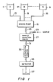
- FIG. l a liquid chromatography system is schematically illustrated for the purpose of showing one very specific application of the mixing pump improvements of the present invention.
- a container ll of a liquid solvent A is connected by a supply tube l3 to a mixing pump system l5.
- a second container l7 holds a different solvent B that is connected to the mixing pump l5 through a conduit l9.
- only two solvents A and B are used.
- additional solvents are utilized, an indefinite additional number being illustrated by another container 2l of the Nth solvent that communicates by a conduit 23 with the mixing pump l5.
- the mixing pump l5 mixes the input solvents in a predetermined manner to be explained hereinafter, and delivers the mixture under pressure in a conduit 25.
- a sample injection valve 27 that introduces a small liquid sample therein that is applied through a sample tube 29.
- the combined solvent with sample is then delivered through a tube 3l to a separation column 33, a primary element of a standard chromatograph.
- the separation column includes beads that are coated with a composition that retains the sample material from the flow in the conduit 3l.
- a gradual change in the composition of the solvent liquid that is applied to the column 33 liberates different constituents of the sample material from the beads at different times. It is the mixing pump l5 that causes the composition of the solvent flow through the separation column 33 to change over time in a precise, predetermined way.
- the solvent with sample material is then passed through a detector 35. The presence of quantities of sample material constituents at different times tells the analyst the composition of the sample material originally injected into the tube 29.
- the liquid is then discharged from the detector into a container 37. That liquid can be considered as waste, and discarded, or can be collected in separate containers at the times that the different sample constitutents are being discharged from the column 33.
- each displacement chamber contains, in this embodiment, cylinders 40 and 42, and pistons 43 and 45 respectively.
- the pistons are operated to control the volumes of their respective chambers.
- the two displacement chambers are connected in parallel. That is, the discharge from each of the chambers 39 and 4l passes through their respective outlet conduits 47 and 49, through their respective check valves 5l and 53, and into the single liquid output conduit 25.
- liquid inputs in the conduits l3, l9 and 23 are applied through their respective valves 57, 59 and 6l, to a common intake conduit 63.
- check valves 5l, 53, 65 and 67 could be replaced by actively driven valves.
- the valves 57, 59 and 6l may be individual valves that are electrically controlled by signals in control lines 7l, 73 and 75, respectively. Alternatively, a single mechanical proportioning valve may be substituted for the individual valves 57, 59 and 6l. In either case, the purpose of the input valves is to connect one liquid solvent at a time to a displacement chamber that is being charged. For example, withdrawal of the piston 43 in the chamber 39 will cause fluid to flow through the check valve 65 into the chamber 59, the fluid so flowing being chosen by connecting one of the conduits l3, l9 or 23 at a time into the common input line 63.
- a separate electric motor 77 is provided for driving the piston 43, and another separate motor 79 is provided for driving the piston 45.
- Each of these motors may be chosen from among those readily available, such as a stepper motor or a direct current motor with a servo feedback control added. In any case, each of the motors is chosen to be of a type that can accurately and predictably position its respective piston within its respective displacement chamber.
- Control signals for the motors are provided in circuits 8l and 83, respectively.
- Suitable control electronics 85 are designed to provide the appropriate signals in the lines 7l, 73, 75, 8l and 83 in order to cooperatively move the pistons and open the intake valves in order to operate the pump system of Figure 2 in a particular, predetermined manner.
- Figures 3 through 6 Two such particular operable configurations for the pump of Figure 2 are illustrated in Figures 3 through 6.
- Figures 3 and 4 illustrate an operable configuration where the displacement of the pistons 43 and 45 is altered when it is desired to change the flow rate in the output 25 of the pump.
- the piston stroke of existing pumps cannot be changed because they are driven from a common motor source through an interlocked mechanical system.
- FIG. 5 A second exemplary operable configuration for the improved mixing pumping system of Figure 2 is illustrated in Figures 5 and 6.
- the piston stroke lengths remain constant and the flow rate in the output 25 is adjusted by varying the velocity of the piston during the discharge portion of its stroke.
- the intake or charge time interval is constant for each of the displacement chambers, no matter what output flow is desired from the pump. Therefore, the same amount of time is provided for operation of the intake valves 57, 59 and 6l in order to assure accurately metered proportions of the different liquid components of the output mixture desired.
- the fixed chamber intake time allows a smoother gradient in the mixture in the output 25.
- Figure 3(A) shows the flow into and out of each of the displacement chambers 39 and 4l. Shown in a solid curve 9l is the flow through the conduit 47 of the chamber 39. Shown in a dashed curve 93 is, similarly, the flow in conduit 49 to and from the displacement chamber 4l.
- the motors 77 and 79 are driving their respective pistons 43 and 45 essentially l80° out of phase with each other; that is, as one is filling its respective chamber, the other is discharging liquid from its chamber.
- a portion of each curve 9l and 93 above the middle "0" line shows a flow out of the respective displacement chamber, while that below the "0" line shows fluid flow into the respective chamber.
- a dashed line 95 shows an ideal output gradient; that is, the ideally linear gradual change from, in this example, a low percentage of component A in the output mixture at the beginning, to a higher percentage of component A at a later time.
- a step function curve 97 reflects the actual variation in the composition of a mixture in the output 25. It is a step function since the composition of the pumps output can change only at times tl, t2, etc.
- the mixture of components A and B that are drawn into the chamber 9l during the time period tl-t2 is then discharged in the next time period t2-t3, that mixture being indicated at 99 on Figure 3(B).
- the mixture of components A and B drawn into the chamber 4l during the time period t2-t3 is that discharged from the output 25 during the next half-cycle, between times t3-t4, and is shown on Figure 3(B) to have a percentage of component A indicated at l0l.
- a maximum intake flow indicated at l03 of Figure 3(A), and a maximum discharge flow indicated at l05 is determined in this specific example by the displacement of the pistons in the respective chambers. The time interval for intake and discharge remains a predetermined fixed value. If it is desired to change that flow, as illustrated in Figure 4, the piston stroke is adjusted accordingly. With reference to Figure 4(A), for example, one-half the output flow rate is provided by shortening the piston stroke length by one-half. An output flow rate indicated at l07 is chosen, for this example, to be one-half of that indicated at l05 in Figure 3(A). Of course, the intake stroke is also one-half of the previous example, a maximum intake flow rate indicated at l09. Figure 4(A) is otherwise similar to Figure 3(A).
- the pump of Figure 2 is operating according to the specific example of Figure 5 with its chamber 4l being charged with liquid constituents A and B in time sequence, as shown by curve ll3 of Figure 5(A), while the chamber 39 is discharging at a maximum rate ll9, as indicated by the curve lll.
- both of the chambers 39 and 4l are discharging, the one that has just been filled discharging at a gradually increasing flow rate while the chamber that had been discharging at a maximum rate during the interval tl-t2 now discharging at a gradually decreasing flow rate.
- the total flow from the two chambers, in this example is maintained constant so that the flow rate at the output 25 of the pump is constant.
- the individual flows from the chambers need not necessarily be linearly increasing or decreasing, but the sum of the discharges from the two should be constant over time. This mixing makes the output composition gradually change from a level l20 to l2l in the interval t2-t3.
- the chamber 39 is being charged with a somewhat different mixture of liquid from the solvents A and B, the proportion of A being greater than during the chamber 4l fill of times tl-t2.
- the chamber 4l as indicated by the curve ll3, is discharging fluid at the maximum rate ll9.
- both chambers are again simultaneously discharging through the common pump output 25, the one that has just been filled linearly increasing its flow, and the other decreasing its flow.
- the interval between time tl and t5 constitutes a complete, single cycle of the pump's operation, which is then repeated.
- the changing composition of the mixture at the output 25 is shown over the same time period in Figure 5(B).
- the mixture at times t5-t6, indicated at l23, is that drawn into the chamber 39 during the previous fill interval t3-t4.
- the velocity profile of piston movement during the intake stroke can be modified, such as stopping it during the portion of the stroke when the valves 57 and 59 are operated to switch from one liquid component to the other. This can provide greater precision in solvent proportioning.
- Prior devices, with a common piston driving mechanism, would also stop the discharge flow for the period that the intake flow is stopped.
- Another advantage of the separate piston motor drive is that the velocity profile of the piston during its delivery stroke can be modified to compensate for the compressibility of the liquid. This can be done without having to affect in any way the intake stroke.
Landscapes
- Engineering & Computer Science (AREA)
- Physics & Mathematics (AREA)
- General Physics & Mathematics (AREA)
- Automation & Control Theory (AREA)
- Mechanical Engineering (AREA)
- General Engineering & Computer Science (AREA)
- Computer Hardware Design (AREA)
- Reciprocating Pumps (AREA)
- Control Of Positive-Displacement Pumps (AREA)
- Treatment Of Liquids With Adsorbents In General (AREA)
Description
- This invention relates to an apparatus for mixing and delivering fluid as claimed in the first part of
claim 1. In a known apparatus of this type (DE-C-901 626) the common intake conduit contains at least one valve which is to be shut or opened, respectively, in addition to the operation of valves arranged each in one of said supply conduits in order to perform the desired mixing proportion. No means are provided to independently change the displacement in each chamber, which is, however, known in an apparatus for pumping a single fluid at a precise rate (EP-A-84070). - The requirements of a mixing pump system in a liquid chromatograph are very stringent. Liquid flow into its separation column must have a substantially uniform flow rate and liquid pressure. Further, in gradient chromatography, the composition of the liquid so supplied must be gradually altered over time. Separate liquid constituents are mixed together in varying relative concentrations over time by the mixing pump system.
- There are basically two categories of liquid mixing pumps that have previously been used for such an application. One category is known as a high pressure mixing pump system, and the other category is known as a low pressure mixing pump system.
- In the high pressure mixing pump system, as e.g. known from US-A-3 869 067, each liquid constituent, or component, to be mixed is connected from a reservoir of that component to an input of its own liquid pump. That is, each component is put under pressure by its own dedicated pump, and the outputs of each of the component pumps are joined together to form the output of the mixing pump system that is connected to the separation column of a liquid chromatograph, in that particular application. The flow rate of each pump is adjusted to provide the right proportions of the liquid components in its output, and to control the total flow velocity in that output. A usual application requires the proportions of the components to change over time, termed "gradient" flow, which requires the flow rates of the individual pumps to be appropriately changed over time to accomplish this. For example, if two components are being supplied in the mixing pump output with the percentage of one component increasing over time and that of the other component decreasing, the respective pumps for these components have their flow rates respectively increased and decreased over time in order to alter the balance of component concentrations without changing the total output flow rate.
- A significant disadvantage of high pressure mixing systems is that a separate pump is required for each solvent or other liquid component that is being mixed. In some cases, more than two such components must be mixed. In the liquid chromatograph supply application particularly, the pumps must be of high precision and thus are very expensive. Typically, each such pump includes two displacement chambers, or syringes, that are operated approximately l80° out of phase so that one pump chamber is discharging fluid while the other is charging. This category of high pressure system has a significant operating advantage, however, in that the component concentration in the output flow can be smoothly varied over time since each of the component pumps can have their flow rate independently adjusted.
- The second category of mixing pump systems is termed a low pressure type. In this type, a single pump is utilized with each of the solvents, or other liquid components, connected from their separate sources to the input of the pump. Dual displacement chambers, or syringes, are generally used to make up this pump. Each liquid component supply is connected to the intake of the pump through a control valve. The pump is operated so that when a displacement chamber is being charged, each liquid component control valve is turned on for a portion of the charging part of the cycle. That is, in the usual case of a piston type displacement chamber, the valve of one constituent supply is opened for a first part of the intake stroke of the piston, it is then closed, and a valve of a second liquid component supply is opened for a time, and so forth, for each of the components that are to be mixed. While one displacement chamber is being charged with a mixture of components in a particular proportion, the other displacement chamber is discharging its previously mixed liquid. The two pistons of the two displacement chambers are mechanically connected to operate essentially l80° out of phase with each other. The result is a liquid output whose composition changes in a step function fashion; that is, when the particular mixture in one chamber is completely discharged, the next chamber begins to discharge a mixture which usually is different in its percentage of liquid components. Thus, there is a sudden change in the proportion of components of the mixture when the discharge of one pump chamber ends and the other begins.
- An advantage of the low pressure category of mixing pump systems is that only one pump with a pair of displacement chambers is required, in combination with appropriate intake valving of the various liquid component supplies, thereby minimizing the complexity and cost of a high precision pumping system. A disadvantage, however, of this category of mixing pumps, is its limited output flow rate range. The maximum flow rate is limited by the switching speed of the component liquid intake valves. As the output flow rate increases, the speed of the pump has to increase, which results in the intake stroke time being reduced. At some point, the intake stroke time becomes too short for the inlet valves to switch with enough control to provide the precise proportions of components desired during the short intake stroke.
- The low pressure mixing systems also have a lower limitation of output flow. As the flow rate of such a pumping system decreases, the time for the delivery stroke becomes very long. Since the composition of the various liquid components in the displacement chamber is not changed during each discharge stroke, the pump system output composition has to remain the same for the duration of the delivery of each discharge stroke. The slower the pump operates, the longer is the duration of discharge of a particular fixed mixture. Since such a mixing pump system is usually utilized where the output mixture is desired to have a gradual change in relative concentrations of its components, there is some limit as to how long this period of constant output mixture can be tolerated. Thus, this places a lower limit on the flow rate available from the low pressure category of pumps.
- Some improvements have been made in the operation of both categories of pumps by paying attention to the mechanical drive interconnection between the pistons of the two displacement chambers. Rather than operating exactly 180° out of phase with the other, such linkages have been provided so that the common motive source of the pump provides a slightly longer discharge time of each chamber than its intake time. The reason for this is to smooth out the liquid flow rate by avoiding any discontinuities when one displacement chamber ends its discharge stroke and the other begins. In many applications, such as in the liquid chromatograph, a flow of uniform velocity and pressure is quite important. But such improvements have not addressed the more basic limitations of such pumping systems that are described above.
- The problem underlying the present invention is to provide an apparatus according to the first part of
claim 1, which is mechanically simple, and thus of low cost, but which provides a liquid output that smoothly and accurately varies the composition of the fluid output over a wide range of pump output flow rates, and which may be adapted for a wide variety of specific applications and requirements. - This problem is accomplished by
claim 1. - In the apparatus of the invention, briefly, a single pump of at least two displacement chambers is provided wherein each chamber is separately driven in a manner that is independent of the other. In a preferred form of the invention, each displacement chamber includes a piston that is driven by a separate electrical motor. The motors are in turn controlled by appropriate control electronics in order to provide desired predetermined relative operation of the pistons. The fluid components to be mixed are connected to the intakes of the displacement chambers through electrically operated valves that are also controlled by the control electronics. The outputs of the displacement chambers are connected together to form a common pump output. The structure of the pumping system is similar to that of the low pressure category of pumps discussed above, except that its driving pistons are no longer connected to a common motor drive source but rather have been mechanically uncoupled from each other so that they may be independently operated.
- It has been discovered that independent control of the intake and discharge portions of the piston cycle can lead to some very beneficial improvements in the smoothing of the change (gradient) of the output liquid mixture. According to one specific aspect of the present invention, the intake portion of the cycle is made a fixed duration of time for any discharge flow rate over a wide range. The fixed intake time allows the inlet valves to be operated in the same manner independent of the output flow rate of the pumping system.
- In one specific form of the fixed intake time feature of the present invention, the piston stroke distance is made larger and its velocity is increased, so the pump cycle time remains the same when the flow rate output is desired to be increased. Existing mechanical linkages of the pistons do not allow varying the piston stroke length, but an independent motor drive does. A significant added advantage of this improved operation is that the duration of time during which the output has an unchanging mixture also remains the same, no matter what the output flow rate; that is, the duration of the steps in mixture of the liquid components is held fixed in time as the pump flow rate is increased. This is not the case with existing low pressure mixing pumps where the steps of constant mixture output increase in duration as the flow rate decreases, making the output gradient depart further from the desired continuous function.
- In another specific form of the fixed intake time aspect of the present invention, the stroke is held constant and the piston velocity profile is the same on each intake stroke over the full range of output flow rates. In this case, the discharge portion of the stroke is controlled, independent of the intake stroke, to provide the desired output flow rate. The discharge portion of the cycle is made to take more time than that of the fixed intake portion, as the flow decreases, so there is a significant overlap wherein both displacement chambers are simultaneously discharging fluid into their common output. This allows a gradual change in the pump output from the mixture of one displacement chamber to that of the other. This combines the best features of both the low pressure and high pressure types of mixing pump systems. The time that the mixture in the pump output has to be that of a single displacement chamber is the fixed time of the intake stroke; this time does not increase as the output flow rate is decreased.
- Additional objects, advantages and features of the various aspects of the present invention will become apparent from the following description of its preferred embodiment, which description should be taken in conjunction with the accompanying drawings.
-
- Figure l illustrates a liquid chromatograph that utilizes the improved mixing pump techniques of the present invention;
- Figure 2 shows the physical structure of the improved mixing pump of the present invention;
- Figures 3 and 4 are curves that illustrate the operation of the mixing pump of Figure 2, according to one specific embodiment thereof; and
- Figures 5 and 6 are curves which illustrate the operation of the mixing pump of Figure 2, according with another specific embodiment thereof.
- Referring initially to Figure l, a liquid chromatography system is schematically illustrated for the purpose of showing one very specific application of the mixing pump improvements of the present invention. A container ll of a liquid solvent A is connected by a supply tube l3 to a mixing pump system l5. Similarly, a second container l7 holds a different solvent B that is connected to the mixing pump l5 through a conduit l9. In some applications, only two solvents A and B are used. In other applications, however, additional solvents are utilized, an indefinite additional number being illustrated by another container 2l of the Nth solvent that communicates by a
conduit 23 with the mixing pump l5. - The mixing pump l5 mixes the input solvents in a predetermined manner to be explained hereinafter, and delivers the mixture under pressure in a
conduit 25. For a liquid chromatograph instrument, it is important that the flow in theoutput conduit 25 be of uniform velocity and pressure. That flow passes through asample injection valve 27, that introduces a small liquid sample therein that is applied through asample tube 29. The combined solvent with sample is then delivered through a tube 3l to a separation column 33, a primary element of a standard chromatograph. As is well known, the separation column includes beads that are coated with a composition that retains the sample material from the flow in the conduit 3l. - A gradual change in the composition of the solvent liquid that is applied to the column 33 liberates different constituents of the sample material from the beads at different times. It is the mixing pump l5 that causes the composition of the solvent flow through the separation column 33 to change over time in a precise, predetermined way. The solvent with sample material is then passed through a
detector 35. The presence of quantities of sample material constituents at different times tells the analyst the composition of the sample material originally injected into thetube 29. The liquid is then discharged from the detector into acontainer 37. That liquid can be considered as waste, and discarded, or can be collected in separate containers at the times that the different sample constitutents are being discharged from the column 33. - Referring to Figure 2, the mixing pump l5, utilizing the various aspects of the present invention is described. At the heart of the pumping unit are two
displacement chambers 39 and 4l. Each displacement chamber contains, in this embodiment,cylinders pistons chambers 39 and 4l passes through theirrespective outlet conduits respective check valves 5l and 53, and into the singleliquid output conduit 25. Similarly, liquid inputs in the conduits l3, l9 and 23 are applied through theirrespective valves common intake conduit 63. Theliquid openings displacement chambers 39 and 4l, respectively, receive liquid from thecommon input conduit 63 through their respectiveinput check valves 65 and 67. Alternatively,check valves - The
valves control lines individual valves piston 43 in thechamber 39 will cause fluid to flow through thecheck valve 65 into thechamber 59, the fluid so flowing being chosen by connecting one of the conduits l3, l9 or 23 at a time into thecommon input line 63. - Instead of driving the
pistons electric motor 77 is provided for driving thepiston 43, and anotherseparate motor 79 is provided for driving thepiston 45. Each of these motors may be chosen from among those readily available, such as a stepper motor or a direct current motor with a servo feedback control added. In any case, each of the motors is chosen to be of a type that can accurately and predictably position its respective piston within its respective displacement chamber. Control signals for the motors are provided incircuits 8l and 83, respectively.Suitable control electronics 85 are designed to provide the appropriate signals in thelines - Two such particular operable configurations for the pump of Figure 2 are illustrated in Figures 3 through 6. Figures 3 and 4 illustrate an operable configuration where the displacement of the
pistons output 25 of the pump. The piston stroke of existing pumps cannot be changed because they are driven from a common motor source through an interlocked mechanical system. - A second exemplary operable configuration for the improved mixing pumping system of Figure 2 is illustrated in Figures 5 and 6. In this second example, the piston stroke lengths remain constant and the flow rate in the
output 25 is adjusted by varying the velocity of the piston during the discharge portion of its stroke. - In both of these examples described below, the intake or charge time interval is constant for each of the displacement chambers, no matter what output flow is desired from the pump. Therefore, the same amount of time is provided for operation of the
intake valves output 25. These are significant improvements over the existing low pressure type mixing pump system. Subject to some constraints, the intake and discharge strokes may be optimized independently of each other since thepistons - Referring initially to Figure 3, the first specific example will be described. Figure 3(A) shows the flow into and out of each of the
displacement chambers 39 and 4l. Shown in a solid curve 9l is the flow through theconduit 47 of thechamber 39. Shown in a dashedcurve 93 is, similarly, the flow inconduit 49 to and from the displacement chamber 4l. In this example, it can be seen that themotors respective pistons curve 9l and 93 above the middle "0" line shows a flow out of the respective displacement chamber, while that below the "0" line shows fluid flow into the respective chamber. - It will be noted from curve 9l of Figure 3(A) that the
valves chamber 39 for a certain portion of the intake cycle that is illustrated between times tl and t2. During the remainder of the time the liquid component B is drawn into the chamber from the supply l7. In the examples shown in Figures 3-6, only two components A and B are assumed to be utilized, for simplicity in explanation, but it will be understood that additional liquid components can be introduced in the same manner, if desired. - Referring to Figure 3(B), the relative proportions of the components A and B in the flow from the
output 25 are illustrated. A dashedline 95 shows an ideal output gradient; that is, the ideally linear gradual change from, in this example, a low percentage of component A in the output mixture at the beginning, to a higher percentage of component A at a later time. Astep function curve 97, however, reflects the actual variation in the composition of a mixture in theoutput 25. It is a step function since the composition of the pumps output can change only at times tl, t2, etc. The mixture of components A and B that are drawn into the chamber 9l during the time period tl-t2 is then discharged in the next time period t2-t3, that mixture being indicated at 99 on Figure 3(B). Similarly, the mixture of components A and B drawn into the chamber 4l during the time period t2-t3 is that discharged from theoutput 25 during the next half-cycle, between times t3-t4, and is shown on Figure 3(B) to have a percentage of component A indicated at l0l. - A maximum intake flow indicated at l03 of Figure 3(A), and a maximum discharge flow indicated at l05, is determined in this specific example by the displacement of the pistons in the respective chambers. The time interval for intake and discharge remains a predetermined fixed value. If it is desired to change that flow, as illustrated in Figure 4, the piston stroke is adjusted accordingly. With reference to Figure 4(A), for example, one-half the output flow rate is provided by shortening the piston stroke length by one-half. An output flow rate indicated at l07 is chosen, for this example, to be one-half of that indicated at l05 in Figure 3(A). Of course, the intake stroke is also one-half of the previous example, a maximum intake flow rate indicated at l09. Figure 4(A) is otherwise similar to Figure 3(A).
- It is extremely interesting to compare the output mixture gradient 97ʹ of Figure 4(B) with the
gradient 97 of Figure 3(B). They are identical since the intake and discharge times are, respectively, the same as that in the Figure 3 example. The flat portion of the curve 97ʹ of Figure 4(B) remains the same as that of thecurve 97 of Figure 3(B). The output gradient does not depart any further from the ideal desired straight line 95 (95ʹ) when the output pump flow is decreased, contrary to the case in existing low pressure type mixing pumps. - The second specific operational example for the mixing pump l5 is described with respect to Figures 5 and 6, each of which is a curve showing information similar to that previously described with respect to Figures 3 and 4, but for fixed stroke, fixed intake time operating conditions. Referring initially to Figure 5(A), the flow into and out of
chamber 39 is indicated by a curve lll in solid outline. Similarly, the flow into and out of the chamber 4l is shown by a curve ll3 in dotted outline. In Figure 5(B), a desired linear gradient change in the mixture at theoutput 25 is shown by a dashed line ll5, the actual mixture as a function of time, for this specific embodiment, being shown as a solid line ll7. - Between times tl and t2, the pump of Figure 2 is operating according to the specific example of Figure 5 with its chamber 4l being charged with liquid constituents A and B in time sequence, as shown by curve ll3 of Figure 5(A), while the
chamber 39 is discharging at a maximum rate ll9, as indicated by the curve lll. During a time interval t2-t3, both of thechambers 39 and 4l are discharging, the one that has just been filled discharging at a gradually increasing flow rate while the chamber that had been discharging at a maximum rate during the interval tl-t2 now discharging at a gradually decreasing flow rate. The total flow from the two chambers, in this example, is maintained constant so that the flow rate at theoutput 25 of the pump is constant. The individual flows from the chambers need not necessarily be linearly increasing or decreasing, but the sum of the discharges from the two should be constant over time. This mixing makes the output composition gradually change from a level l20 to l2l in the interval t2-t3. - In the next interval of time t3-t4, the
chamber 39 is being charged with a somewhat different mixture of liquid from the solvents A and B, the proportion of A being greater than during the chamber 4l fill of times tl-t2. At that same time, the chamber 4l, as indicated by the curve ll3, is discharging fluid at the maximum rate ll9. - During the next interval of time t4-t5, both chambers are again simultaneously discharging through the
common pump output 25, the one that has just been filled linearly increasing its flow, and the other decreasing its flow. The interval between time tl and t5 constitutes a complete, single cycle of the pump's operation, which is then repeated. - The changing composition of the mixture at the
output 25 is shown over the same time period in Figure 5(B). The mixture (percentage of component A) being discharged during the time period t3-t4, indicated at l2l, is the mixture that was drawn into the chamber 4l during the time period tl-t2. Similarly, the mixture at times t5-t6, indicated at l23, is that drawn into thechamber 39 during the previous fill interval t3-t4. - Referring to Figure 6, the same basic operational example as Figure 5 is given, except that the flow rate is reduced to one-half, while the desired gradient is the same. This reduced flow rate is indicated at l25 of Figure 6. The reduced flow rate is accomplished by reducing the velocity of the piston during its discharge portion of its stroke, and this increases the time for discharge. The velocity and duration of the intake portion remain the same, as discussed previously. This means that the flat portions of the curve ll7ʹof Figure 6(B) remain of the same duration; that is, it is only during this fixed duration of the intake stroke of one chamber that liquid of unchanging composition is being discharged to the
output 25 from the other chamber. This is an improvement over existing low pressure mixing pumps that increase the flat portions of their curves corresponding to curve ll7ʹ in the same proportion as the total pump cycle time. - There are many other variations of these two specific modes of operating the pump of Figure 2 that are obviously available. For example, the velocity profile of piston movement during the intake stroke can be modified, such as stopping it during the portion of the stroke when the
valves - Another advantage of the separate piston motor drive is that the velocity profile of the piston during its delivery stroke can be modified to compensate for the compressibility of the liquid. This can be done without having to affect in any way the intake stroke.
- The concepts of the present invention have been described as implemented in a liquid pump especially adapted for a liquid chromatograph. Of course, it will be understood, that the concepts have applicability in liquid pumps for other applications, particularly those with high precision requirements of liquid flow and mixture control. Also, the configuration of the pump described is also useful for mixing and pumping air and other gases. Further, it is useful for other substances that can be handled like fluids, such as slurries.
- Although the various aspects of the present invention have been described with respect to preferred embodiments thereof, it will be understood that the invention is to be protected within the full scope of the appended claims.
Claims (9)
- Apparatus for mixing and delivering fluid, comprising: pumping means having at least two displacement chambers (39,41), each chamber having a fluid intake and a fluid output,
independent sources (11,17,21) of at least two fluids, each said source having a fluid outlet formed by an individually blockable supply conduit (13,19,23),
intake connecting means (63,65,67) for connecting each of the fluid sources (11,17,21) together to the fluid intakes of each of said chambers (39,41) for providing a controllable proportion of said fluids from said sources to said intakes, said intake connecting means including intake valve means (65,67) for connecting said chambers (39,41) to said supply conduits (13,19,23) and output valve means (51,53) for connecting the outputs of the chambers together for forming a single fluid output (25),
characterized in that said intake connecting means (63,65,67) include a common intake conduit (63), which connects said blockable supply conduits (13,19,23) permanently to said chambers (39,41), and in that
control means (77,79,85) are provided for concurrent control of said intake valve means (65,67) and for the displacement in each of said chambers (39,41), such that a single fluid at a time is supplied to a displacement chamber that is charged. - Apparatus according to claim 1,
characterized in that said control means (77,79,85) include means (77,79) for changing the fluid flow through the output of each of said displacement chambers (39,41) independently of the fluid flow through the common intake conduit (63) of said chambers, whereby the characteristics of fluid intake and discharge can be independently optimized for each displacement chamber for a given flow rate. - Apparatus according to claim 1 or 2,
characterized in that valves (57,59,61) are arranged in said supply conduits (13,19,23), which are controlled to open or block fluid flow through said supply conduits by said control means (77,79,85). - Apparatus according to claim 3,
characterized in that said control means (77,79,85) maintain preselected time period of fluid intake during each cycle of operation of each of said two chambers (39,41). - Apparatus according to one of the preceding claims,
characterized in that said control means (77,79,85) adjust the flow rate of fluid discharged from the chamber's output, whereby an intake cycle portion can be optimized for mixing the source fluids (11,17,21) upon intake to each chamber and an output cycle portion thereof can be independently set for a desired fluid output. - Apparatus according to claim 4 or 5,
characterized in that said control means (77,79,85) additionally include means for causing said chambers (39,41) to simultaneously discharge fluid from their outputs through said single fluid output (25). - Apparatus according to one of claims 4 to 6,
characterized in that said control means (77,79,85) additionally include means for causing the fluid output of one chamber (39,41) to gradually increase while causing the fluid output of the other chamber (41,39) to gradually decrease during a time period of simultaneous fluid discharge from the chambers, the discharge of each chamber additionally being caused to be a maximum and substantially constant during the fixed intake time period of the other chamber. - Apparatus according to claim 5,
characterized in that said control means (77,79,85) sets a maximum volume of displacement of said at least two chambers (39,41). - Use of an apparatus according to one of the preceding claims in a liquid chromatography system,
characterized in that
a sample injector (27) is positioned in the path of a single pumping means liquid output,
a chromatograph column (33) receives the single pumping means output after passing through said sample injector, and
a detector (35) is positioned at the output of said column.
Applications Claiming Priority (2)
| Application Number | Priority Date | Filing Date | Title |
|---|---|---|---|
| US841922 | 1986-03-20 | ||
| US06/841,922 US4714545A (en) | 1986-03-20 | 1986-03-20 | Fluid proportioning pump system |
Publications (2)
| Publication Number | Publication Date |
|---|---|
| EP0240658A1 EP0240658A1 (en) | 1987-10-14 |
| EP0240658B1 true EP0240658B1 (en) | 1992-04-29 |
Family
ID=25286057
Family Applications (1)
| Application Number | Title | Priority Date | Filing Date |
|---|---|---|---|
| EP87101275A Expired EP0240658B1 (en) | 1986-03-20 | 1987-01-30 | Fluid proportioning pump system |
Country Status (6)
| Country | Link |
|---|---|
| US (1) | US4714545A (en) |
| EP (1) | EP0240658B1 (en) |
| JP (1) | JPS62247831A (en) |
| DE (1) | DE3778578D1 (en) |
| HK (1) | HK101392A (en) |
| SG (1) | SG104192G (en) |
Families Citing this family (34)
| Publication number | Priority date | Publication date | Assignee | Title |
|---|---|---|---|---|
| GB2195474B (en) * | 1986-09-17 | 1991-01-23 | Philips Electronic Associated | Liquid chromatograph |
| US4919595A (en) * | 1987-03-03 | 1990-04-24 | Beckman Instruments, Inc. | Fluid delivery system with deficit flow compensation |
| US4954253A (en) * | 1987-05-14 | 1990-09-04 | Nauchno-Tekhnicheskoe Objedinenie Akademii Nauk Sssr | Device for preparing a gradient solution for a high-pressure liquid chromatograph |
| DE3785207T2 (en) * | 1987-09-26 | 1993-07-15 | Hewlett Packard Gmbh | PUMP DEVICE FOR DISPENSING LIQUID AT HIGH PRESSURE. |
| CN1019861B (en) * | 1988-06-09 | 1992-12-30 | 成都科技大学 | Electricity is led detection formula low-voltage ion chromatograph |
| DE3918307A1 (en) * | 1989-06-05 | 1990-12-13 | Roediger Ag | AREA GASIFIER |
| WO1991000560A1 (en) * | 1989-06-30 | 1991-01-10 | Nauchno-Proizvodstvennaya Assotsiatsia 'transsonik' | System for dosing and mixing of liquid components |
| WO1991000561A1 (en) * | 1989-07-05 | 1991-01-10 | Nauchno-Proizvodstvennaya Assotsiatsia 'transsonik' | System for dosing and mixing liquid components of a mixture |
| US5635070A (en) * | 1990-07-13 | 1997-06-03 | Isco, Inc. | Apparatus and method for supercritical fluid extraction |
| JPH0510959A (en) * | 1991-07-04 | 1993-01-19 | Sanuki Kogyo Kk | Compound liquid mixture feeding device for physical/ chemical machine |
| US5360320A (en) * | 1992-02-27 | 1994-11-01 | Isco, Inc. | Multiple solvent delivery system |
| US5664938A (en) * | 1992-03-05 | 1997-09-09 | Yang; Frank Jiann-Fu | Mixing apparatus for microflow gradient pumping |
| US5630706A (en) * | 1992-03-05 | 1997-05-20 | Yang; Frank J. | Multichannel pump apparatus with microflow rate capability |
| US5253981A (en) * | 1992-03-05 | 1993-10-19 | Frank Ji-Ann Fu Yang | Multichannel pump apparatus with microflow rate capability |
| US5415489A (en) * | 1993-01-11 | 1995-05-16 | Zymark Corporation | Reciprocating driver apparatus |
| JP3491948B2 (en) * | 1993-03-05 | 2004-02-03 | ウォーターズ・インベストメンツ・リミテッド | Solvent pump feeder |
| US5370799A (en) * | 1993-03-16 | 1994-12-06 | Gas Research Institute | Elevated temperature-pressure flow simulator |
| US5388761A (en) * | 1993-10-01 | 1995-02-14 | Langeman; Gary D. | Plural component delivery system |
| US5620524A (en) * | 1995-02-27 | 1997-04-15 | Fan; Chiko | Apparatus for fluid delivery in chemical vapor deposition systems |
| EP1376121A1 (en) * | 2002-06-29 | 2004-01-02 | Agilent Technologies Inc. a Delaware Corporation | Pumping arrangement |
| US6780315B2 (en) * | 2002-12-09 | 2004-08-24 | Waters Investments Limited | Backflow prevention for high pressure gradient systems |
| GB2433792B (en) * | 2004-07-13 | 2008-09-10 | Waters Investments Ltd | High pressure pump controller |
| WO2006087036A1 (en) * | 2005-02-16 | 2006-08-24 | Agilent Technologies, Inc. | Fluid pump having low pressure metering and high pressure delivering |
| US20070000947A1 (en) * | 2005-07-01 | 2007-01-04 | Lewis Russell H | Apparatus and methods for dispensing fluidic or viscous materials |
| US20070069040A1 (en) * | 2005-08-15 | 2007-03-29 | Lewis Russell H | Apparatus and methods for dispensing fluidic or viscous materials |
| JP4704228B2 (en) * | 2005-09-06 | 2011-06-15 | 東京応化工業株式会社 | Resist solution supply device and remodeling kit for obtaining the resist solution supply device |
| US8961783B2 (en) | 2008-09-12 | 2015-02-24 | Waters Technologies Corporation | Apparatus and methods for preparative liquid chromatography |
| EP2523749B1 (en) * | 2010-01-11 | 2022-04-13 | Waters Technologies Corporation | System and manifold for solvent mixing in liquid chromatography systems |
| US9499390B1 (en) * | 2012-07-17 | 2016-11-22 | Global Agricultural Technology And Engineering, Llc | Liquid delivery system |
| CH706929A1 (en) * | 2012-09-11 | 2014-03-14 | Werner Doebelin | Ultra-high-pressure syringe pump system for the gradient operation in the field of HPLC. |
| DE102014104708B3 (en) * | 2014-04-02 | 2015-05-21 | Agilent Technologies, Inc. - A Delaware Corporation - | DETERMINATION OF A FLUID LOSS OF A PISTON PUMP BASED ON DRAINING TIME VARIATION |
| US9895708B2 (en) | 2014-10-20 | 2018-02-20 | Akurate Dynamics LLC | System for dispensing multiple component chemical sprays |
| US10568811B2 (en) * | 2016-02-22 | 2020-02-25 | R.P. Scherer Technologies, Llc | Multiple-fluid injection pump |
| US12292041B2 (en) * | 2019-09-24 | 2025-05-06 | Mgi Tech Co., Ltd. | Method and system for transportating fluid, and device employing system and method |
Family Cites Families (11)
| Publication number | Priority date | Publication date | Assignee | Title |
|---|---|---|---|---|
| DE901626C (en) * | 1950-03-22 | 1954-01-14 | Aecherli A G Maschinenfabrik R | Piston pump unit for pumping at least two fluids while simultaneously mixing them in a certain mixing ratio |
| US3869067A (en) * | 1972-06-26 | 1975-03-04 | Du Pont | Apparatus for gradient elution |
| US3917531A (en) * | 1974-02-11 | 1975-11-04 | Spectra Physics | Flow rate feedback control chromatograph |
| US4043906A (en) * | 1976-03-18 | 1977-08-23 | Varian Associates, Inc. | Method and apparatus for reducing the transient effects of liquid compressibility in a liquid chromatography system |
| US4128476A (en) * | 1977-06-14 | 1978-12-05 | Spectra-Physics, Inc. | Carrier composition control for liquid chromatographic systems |
| US4162689A (en) * | 1977-07-14 | 1979-07-31 | Hoffmann-La Roche Inc. | Time division flow control |
| JPS55122149A (en) * | 1979-03-14 | 1980-09-19 | Japan Spectroscopic Co | Method and apparatus for supplying solvent in liquid chromatograph |
| US4333356A (en) * | 1979-04-27 | 1982-06-08 | Ciba-Geigy Corporation | Mixing apparatus |
| US4321014A (en) * | 1979-12-31 | 1982-03-23 | Polaroid Corporation | Constant flow pumping apparatus |
| US4311586A (en) * | 1980-04-22 | 1982-01-19 | Tracor, Inc. | Solvent mixing in HPLC using low pressure solvent metering pumps |
| DE3276590D1 (en) * | 1982-01-15 | 1987-07-23 | Polaroid Corp | Pressure equalization pumping system |
-
1986
- 1986-03-20 US US06/841,922 patent/US4714545A/en not_active Expired - Lifetime
-
1987
- 1987-01-30 EP EP87101275A patent/EP0240658B1/en not_active Expired
- 1987-01-30 DE DE8787101275T patent/DE3778578D1/en not_active Expired - Lifetime
- 1987-03-20 JP JP62067679A patent/JPS62247831A/en active Pending
-
1992
- 1992-10-09 SG SG1041/92A patent/SG104192G/en unknown
- 1992-12-17 HK HK1013/92A patent/HK101392A/en unknown
Also Published As
| Publication number | Publication date |
|---|---|
| JPS62247831A (en) | 1987-10-28 |
| HK101392A (en) | 1992-12-24 |
| EP0240658A1 (en) | 1987-10-14 |
| SG104192G (en) | 1992-12-24 |
| DE3778578D1 (en) | 1992-06-04 |
| US4714545A (en) | 1987-12-22 |
Similar Documents
| Publication | Publication Date | Title |
|---|---|---|
| US4714545A (en) | Fluid proportioning pump system | |
| US4310420A (en) | Mobile phase supplying method in the liquid chromatography and apparatus therefor | |
| US4126399A (en) | Method and apparatus for preparing multi-component plastic materials, particularly polyurethane, with solid material additives or at least one highly viscous component | |
| JPH08284809A (en) | Pump system that keeps the amount of liquid flowing out almost constant | |
| US5447691A (en) | Liquid supplying device for use in physical and chemical apparatus | |
| CN1737372B (en) | Liquid feeding system | |
| US11130074B2 (en) | Hybrid gradient delivery system and operation | |
| US4096059A (en) | Proportioning fluids | |
| EP0583003A1 (en) | Fluid metering, mixing and composition control system | |
| US20110209532A1 (en) | Automatic sampler for liquid chromatograph | |
| US5524797A (en) | Double acting metering cylinder | |
| US4257992A (en) | Method and an apparatus for the production of articles which consist of filler-containing synthetic material, in particular of foam | |
| JP2000087846A (en) | Fluid suction / discharge method and system using a pump having a constant suction or discharge amount | |
| US3932067A (en) | Liquid chromatography apparatus and method | |
| GB2332378A (en) | Liquid chromatography valved pumping system with flow dampers | |
| US4599049A (en) | High pressure meter pump | |
| JPS62147066A (en) | Pump device for mixing and supplying at least two component | |
| US4556367A (en) | Solvent delivery system | |
| EP0085171B1 (en) | Solvent delivery system | |
| US4312594A (en) | Blending vessel and method of blending | |
| JP2617030B2 (en) | Solvent mixing equipment for high performance liquid chromatography | |
| SU767528A1 (en) | Method of continuously metering liquid | |
| SU1282823A3 (en) | Method for controlling ratio of mixture components | |
| US5257722A (en) | Device for filling one or more molds with flowable materials | |
| CN218131670U (en) | Two-component fixed ratio one-way glue output equipment |
Legal Events
| Date | Code | Title | Description |
|---|---|---|---|
| PUAI | Public reference made under article 153(3) epc to a published international application that has entered the european phase |
Free format text: ORIGINAL CODE: 0009012 |
|
| AK | Designated contracting states |
Kind code of ref document: A1 Designated state(s): CH DE FR GB IT LI NL SE |
|
| 17P | Request for examination filed |
Effective date: 19880408 |
|
| 17Q | First examination report despatched |
Effective date: 19900220 |
|
| 17Q | First examination report despatched |
Effective date: 19910925 |
|
| ITTA | It: last paid annual fee | ||
| GRAA | (expected) grant |
Free format text: ORIGINAL CODE: 0009210 |
|
| AK | Designated contracting states |
Kind code of ref document: B1 Designated state(s): CH DE FR GB IT LI NL SE |
|
| REF | Corresponds to: |
Ref document number: 3778578 Country of ref document: DE Date of ref document: 19920604 |
|
| ET | Fr: translation filed | ||
| ITF | It: translation for a ep patent filed | ||
| PGFP | Annual fee paid to national office [announced via postgrant information from national office to epo] |
Ref country code: FR Payment date: 19921210 Year of fee payment: 7 |
|
| PGFP | Annual fee paid to national office [announced via postgrant information from national office to epo] |
Ref country code: SE Payment date: 19921211 Year of fee payment: 7 |
|
| PGFP | Annual fee paid to national office [announced via postgrant information from national office to epo] |
Ref country code: NL Payment date: 19930131 Year of fee payment: 7 |
|
| PLBE | No opposition filed within time limit |
Free format text: ORIGINAL CODE: 0009261 |
|
| STAA | Information on the status of an ep patent application or granted ep patent |
Free format text: STATUS: NO OPPOSITION FILED WITHIN TIME LIMIT |
|
| 26N | No opposition filed | ||
| PG25 | Lapsed in a contracting state [announced via postgrant information from national office to epo] |
Ref country code: SE Effective date: 19940131 |
|
| PG25 | Lapsed in a contracting state [announced via postgrant information from national office to epo] |
Ref country code: NL Effective date: 19940801 |
|
| NLV4 | Nl: lapsed or anulled due to non-payment of the annual fee | ||
| PG25 | Lapsed in a contracting state [announced via postgrant information from national office to epo] |
Ref country code: FR Effective date: 19940930 |
|
| REG | Reference to a national code |
Ref country code: FR Ref legal event code: ST |
|
| PGFP | Annual fee paid to national office [announced via postgrant information from national office to epo] |
Ref country code: CH Payment date: 19941215 Year of fee payment: 9 |
|
| PGFP | Annual fee paid to national office [announced via postgrant information from national office to epo] |
Ref country code: DE Payment date: 19941227 Year of fee payment: 9 |
|
| PGFP | Annual fee paid to national office [announced via postgrant information from national office to epo] |
Ref country code: GB Payment date: 19941228 Year of fee payment: 9 |
|
| EUG | Se: european patent has lapsed |
Ref document number: 87101275.3 Effective date: 19940810 |
|
| PG25 | Lapsed in a contracting state [announced via postgrant information from national office to epo] |
Ref country code: GB Effective date: 19960130 |
|
| PG25 | Lapsed in a contracting state [announced via postgrant information from national office to epo] |
Ref country code: LI Effective date: 19960131 Ref country code: CH Effective date: 19960131 |
|
| REG | Reference to a national code |
Ref country code: CH Ref legal event code: PL |
|
| GBPC | Gb: european patent ceased through non-payment of renewal fee |
Effective date: 19960130 |
|
| PG25 | Lapsed in a contracting state [announced via postgrant information from national office to epo] |
Ref country code: DE Effective date: 19961001 |
|
| PG25 | Lapsed in a contracting state [announced via postgrant information from national office to epo] |
Ref country code: IT Free format text: LAPSE BECAUSE OF NON-PAYMENT OF DUE FEES Effective date: 20050130 |