EP0240278A2 - Improvements relating to gas compressors - Google Patents
Improvements relating to gas compressors Download PDFInfo
- Publication number
- EP0240278A2 EP0240278A2 EP87302717A EP87302717A EP0240278A2 EP 0240278 A2 EP0240278 A2 EP 0240278A2 EP 87302717 A EP87302717 A EP 87302717A EP 87302717 A EP87302717 A EP 87302717A EP 0240278 A2 EP0240278 A2 EP 0240278A2
- Authority
- EP
- European Patent Office
- Prior art keywords
- pressure
- valve
- chamber
- sense
- acting
- Prior art date
- Legal status (The legal status is an assumption and is not a legal conclusion. Google has not performed a legal analysis and makes no representation as to the accuracy of the status listed.)
- Granted
Links
Images
Classifications
-
- F—MECHANICAL ENGINEERING; LIGHTING; HEATING; WEAPONS; BLASTING
- F04—POSITIVE - DISPLACEMENT MACHINES FOR LIQUIDS; PUMPS FOR LIQUIDS OR ELASTIC FLUIDS
- F04B—POSITIVE-DISPLACEMENT MACHINES FOR LIQUIDS; PUMPS
- F04B49/00—Control, e.g. of pump delivery, or pump pressure of, or safety measures for, machines, pumps, or pumping installations, not otherwise provided for, or of interest apart from, groups F04B1/00 - F04B47/00
- F04B49/22—Control, e.g. of pump delivery, or pump pressure of, or safety measures for, machines, pumps, or pumping installations, not otherwise provided for, or of interest apart from, groups F04B1/00 - F04B47/00 by means of valves
- F04B49/24—Bypassing
Definitions
- This invention relates to gas compressors and relates more especially to air compressors fitted with unloader valves which when signalled operate to connect a compression chamber to atmosphere.
- a gas compressor comprising a reciprocating member forming a movable wall of a compression chamber for cyclicly increasing and decreasing the volume thereof to induce and deliver compressed gas to a delivery port, an unloader valve having a biassed valve member acting in a sense to close a vent passage communicating with said chamber said unloader valve being operable by a fluid pressure signal acting on a pressure responsive area in a sense to counteract the bias and characterised by a further area subject to the pressure in said chamber acting in a sense to enhance the bias.
- said further pressure area is at least as large as the area presented to the pressure in said chamber by the valve member in the closed position thereof.
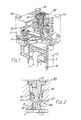
- FIG. 1 this illustrates the upper part of a single cylinder piston-type air compressor, with the crankcase and crankshaft assembly now shown.
- the crankshaft is conmmunicated via a connecting rod, the upper end of which is indicated by reference 1, pivotally connected to a piston 2 via a gudgeon pin 3.
- the piston 2 is thereby reciprocable in a bore 4 of a cylinder 5 alternatively to increase and decrease the volume of a compression chamber6 of which the piston 2 forms one wall.
- the compressor is also conveniently provided with a valve plate 7 carrying a delivery reed valve 8 and an inlet reed valve 9.
- the delivery reed valve 8 provides one way communication from the compression chamber 6 through the valve plate to a delivery port 10 of a cylinder head 11 and the inlet valve 9 provides one way communication between a induction or inlet chamber 12 through a passage 13 in the valve plate.
- the cylinder head and valve plate are assembled to the cylinder by conventional bolts denoted by ref. 14.
- the cylinder head is further provided with an unloader valve illustrated on a larger scale in Fig. 2 and comprising a valve member 15 sealingly slideable in a bore 16 to open and close a passage 17 between the compression chamber 6 and the inlet chamber 12.
- This valve member has an annular pressure responsive area 23 wubject to control pressure at a control port 27 acting in a sense to overcome the bias of a spring 18 when a desired reservoir pressure is attained. Additionally, the pressure responsive member is provided with an internal passage-way 19 which communicates with a further area 20 located to act in a sense to enhance the bias of spring 18 in the presence of pressure in the chamber 6.
- the whole assembly of the unloader valve is held together by a vented closure member 21 located in the cylinder head by an internal circlip 22.
- the closure member 21 being provided with a spigot 25 having an annular seal 23 upon which the valve member is sealingly slideable.
- the unloader valve tends to close during induction strokes but to partially open on compression strokes, such opening being caused by recovering reservoir pressure enhanced by compression chamber pressure acting on the valve closure area of 17.
- the result of this partial opening can be substantial energy dissipation and over heating.
- the additional area 20 is at least as large as the area of the valve member covering the vent passage 17 which is subject to compression chamber pressure in the closed position thereof.
Landscapes
- Engineering & Computer Science (AREA)
- Mechanical Engineering (AREA)
- General Engineering & Computer Science (AREA)
- Compressor (AREA)
Abstract
Description
- This invention relates to gas compressors and relates more especially to air compressors fitted with unloader valves which when signalled operate to connect a compression chamber to atmosphere.
- In air compressors of a type fitted to and driven by heavy vehicle engines for supplying compressed air to reservoirs of compressed air braking systems, it is common to fit an unloader valve signalled in response to a desired reservoir pressure being attained for connecting the compression chamber to atmosphere. Typically, such a valve is fitted in the cylinder head of a piston and cylinder compressor and arranged to open when signalled to connect the compression chamber to the inlet chamber so as to interrupt supply of compressed air to a delivery port and the reservoirs. In such compressors it has been found that undue heating has occurred and the object of the present invention is to reduce such heating.
- According to the present invention there is provided a gas compressor comprising a reciprocating member forming a movable wall of a compression chamber for cyclicly increasing and decreasing the volume thereof to induce and deliver compressed gas to a delivery port, an unloader valve having a biassed valve member acting in a sense to close a vent passage communicating with said chamber said unloader valve being operable by a fluid pressure signal acting on a pressure responsive area in a sense to counteract the bias and characterised by a further area subject to the pressure in said chamber acting in a sense to enhance the bias.
- In a preferred embodiment of the invention said further pressure area is at least as large as the area presented to the pressure in said chamber by the valve member in the closed position thereof.
- In order that the invention may be more clearly understood and readily carried into effect the same will be further described by way of example with reference to the accompanying drawing of which,
- Fig. 1 illustrates a part sectional perspective view of a single cylinder piston air compressor and,
- Fig. 2 illustrates an unloader valve on an enlarged scale.
- Referring to Fig. 1, this illustrates the upper part of a single cylinder piston-type air compressor, with the crankcase and crankshaft assembly now shown. The crankshaft is conmmunicated via a connecting rod, the upper end of which is indicated by reference 1, pivotally connected to a piston 2 via a
gudgeon pin 3. The piston 2 is thereby reciprocable in a bore 4 of a cylinder 5 alternatively to increase and decrease the volume of a compression chamber6 of which the piston 2 forms one wall. The compressor is also conveniently provided with avalve plate 7 carrying a delivery reed valve 8 and an inlet reed valve 9. The delivery reed valve 8 provides one way communication from the compression chamber 6 through the valve plate to adelivery port 10 of acylinder head 11 and the inlet valve 9 provides one way communication between a induction orinlet chamber 12 through a passage 13 in the valve plate. The cylinder head and valve plate are assembled to the cylinder by conventional bolts denoted by ref. 14. The cylinder head is further provided with an unloader valve illustrated on a larger scale in Fig. 2 and comprising avalve member 15 sealingly slideable in abore 16 to open and close apassage 17 between the compression chamber 6 and theinlet chamber 12. This valve member has an annular pressureresponsive area 23 wubject to control pressure at acontrol port 27 acting in a sense to overcome the bias of aspring 18 when a desired reservoir pressure is attained. Additionally, the pressure responsive member is provided with an internal passage-way 19 which communicates with afurther area 20 located to act in a sense to enhance the bias ofspring 18 in the presence of pressure in the chamber 6. The whole assembly of the unloader valve is held together by a ventedclosure member 21 located in the cylinder head by aninternal circlip 22. Theclosure member 21 being provided with aspigot 25 having anannular seal 23 upon which the valve member is sealingly slideable. - Considering the operation of the compressor and the included unloader valve, when the pressure in the reservoir or reservoirs being supplied via the
delivery port 10 has attained a desired pressure value, this pressure applied to thecontrol port 27 and acting on the pressure responsiveannular control area 24 of the unloader valve, is sufficient to lift thevalve member 15 against the bias ofspring 18. Thevent passage 17 is therefore uncovered and the compression chamber 6 is connected to theinlet chamber 12 which is at approximately atmospheric pressure. On a downward stroke of the piston 2, whilst air induced via the inlet valve on the next compression stroke of the piston 2 this air is expelled with minimum energy absorption via theopen passage 17. - Ignoring for the present the
inner area 20 which assists the bias by being connected to the compression chamber, and assuming a small control signal pressure drop occurs at thecontrol port 27, the unloader valve tends to close during induction strokes but to partially open on compression strokes, such opening being caused by recovering reservoir pressure enhanced by compression chamber pressure acting on the valve closure area of 17. The result of this partial opening can be substantial energy dissipation and over heating. By including the additional area subject to the compression chamber pressure and effective in a sense to enhance the bias on the unloader valve, such over heating can be appreciably reduced or prevented. Preferably theadditional area 20 is at least as large as the area of the valve member covering thevent passage 17 which is subject to compression chamber pressure in the closed position thereof.
Claims (3)
Applications Claiming Priority (2)
| Application Number | Priority Date | Filing Date | Title |
|---|---|---|---|
| GB08607955A GB2188682A (en) | 1986-04-01 | 1986-04-01 | Unloader valve for compressor |
| GB8607955 | 1986-04-01 |
Publications (3)
| Publication Number | Publication Date |
|---|---|
| EP0240278A2 true EP0240278A2 (en) | 1987-10-07 |
| EP0240278A3 EP0240278A3 (en) | 1989-08-30 |
| EP0240278B1 EP0240278B1 (en) | 1991-10-16 |
Family
ID=10595495
Family Applications (1)
| Application Number | Title | Priority Date | Filing Date |
|---|---|---|---|
| EP19870302717 Expired EP0240278B1 (en) | 1986-04-01 | 1987-03-30 | Improvements relating to gas compressors |
Country Status (4)
| Country | Link |
|---|---|
| EP (1) | EP0240278B1 (en) |
| DE (1) | DE3773723D1 (en) |
| ES (1) | ES2026529T3 (en) |
| GB (1) | GB2188682A (en) |
Cited By (4)
| Publication number | Priority date | Publication date | Assignee | Title |
|---|---|---|---|---|
| EP0575880A1 (en) * | 1992-06-22 | 1993-12-29 | Bendix Heavy Vehicle Systems Italia S.P.A. | A reciprocating piston volumetric compressor, particularly for pneumatic braking systems |
| US20150167663A1 (en) * | 2013-12-16 | 2015-06-18 | WABCO Compressor Manufacturing Co., | Compressor for a Vehicle Air Supply System |
| CN107667239A (en) * | 2015-04-09 | 2018-02-06 | 奔迪士商业运输系统公司 | Piston component for the feather valve of air compressor |
| EP3718844A1 (en) * | 2019-04-05 | 2020-10-07 | KNORR-BREMSE Systeme für Nutzfahrzeuge GmbH | Piston assembly for an unloader valve of an air compressor |
Families Citing this family (1)
| Publication number | Priority date | Publication date | Assignee | Title |
|---|---|---|---|---|
| GB2319569A (en) * | 1996-11-22 | 1998-05-27 | Knorr Bremse Systeme | Unloading gas compressors |
Family Cites Families (4)
| Publication number | Priority date | Publication date | Assignee | Title |
|---|---|---|---|---|
| FR1352457A (en) * | 1963-03-29 | 1964-02-14 | Normalair Ltd | Vacuum device for compressor |
| DE1940736A1 (en) * | 1969-08-09 | 1971-02-18 | Condor Werk Frede Kg Geb | Control device for compressor systems |
| CH566505A5 (en) * | 1974-04-09 | 1975-09-15 | Von Roll Ag | |
| DE3042069A1 (en) * | 1980-11-07 | 1982-06-16 | Knorr-Bremse GmbH, 8000 München | VALVE DEVICE FOR A PNEUMATICALLY CONTROLLED COMPRESSOR SHUT-OFF COUPLING |
-
1986
- 1986-04-01 GB GB08607955A patent/GB2188682A/en active Granted
-
1987
- 1987-03-30 EP EP19870302717 patent/EP0240278B1/en not_active Expired
- 1987-03-30 DE DE8787302717T patent/DE3773723D1/en not_active Expired - Lifetime
- 1987-03-30 ES ES87302717T patent/ES2026529T3/en not_active Expired - Lifetime
Cited By (9)
| Publication number | Priority date | Publication date | Assignee | Title |
|---|---|---|---|---|
| EP0575880A1 (en) * | 1992-06-22 | 1993-12-29 | Bendix Heavy Vehicle Systems Italia S.P.A. | A reciprocating piston volumetric compressor, particularly for pneumatic braking systems |
| US20150167663A1 (en) * | 2013-12-16 | 2015-06-18 | WABCO Compressor Manufacturing Co., | Compressor for a Vehicle Air Supply System |
| US9657733B2 (en) * | 2013-12-16 | 2017-05-23 | Wabco Compressor Manufacturing Co. | Compressor for a vehicle air supply system |
| CN107667239A (en) * | 2015-04-09 | 2018-02-06 | 奔迪士商业运输系统公司 | Piston component for the feather valve of air compressor |
| CN107667239B (en) * | 2015-04-09 | 2019-10-11 | 奔迪士商业运输系统公司 | Piston assembly for unloader valve of air compressor |
| US10746300B2 (en) | 2015-04-09 | 2020-08-18 | Bendix Commercial Vehicle Systems Llc | Piston assembly for an unloader valve of an air compressor |
| EP3718844A1 (en) * | 2019-04-05 | 2020-10-07 | KNORR-BREMSE Systeme für Nutzfahrzeuge GmbH | Piston assembly for an unloader valve of an air compressor |
| WO2020201429A1 (en) * | 2019-04-05 | 2020-10-08 | Knorr-Bremse Systeme für Nutzfahrzeuge GmbH | Piston assembly for an unloader valve of an air compressor |
| US12258955B2 (en) | 2019-04-05 | 2025-03-25 | Knorr-Bremse Systeme Fuer Nutzfahrzeuge Gmbh | Piston assembly for an unloader valve of an air compressor |
Also Published As
| Publication number | Publication date |
|---|---|
| GB2188682A (en) | 1987-10-07 |
| ES2026529T3 (en) | 1992-05-01 |
| GB2188682B (en) | 1989-11-15 |
| GB8607955D0 (en) | 1986-05-08 |
| EP0240278B1 (en) | 1991-10-16 |
| EP0240278A3 (en) | 1989-08-30 |
| DE3773723D1 (en) | 1991-11-21 |
Similar Documents
| Publication | Publication Date | Title |
|---|---|---|
| EP1490598B1 (en) | Head pressure relief assembly | |
| US5147190A (en) | Increased efficiency valve system for a fluid pumping assembly | |
| US4522568A (en) | Compressor apparatus | |
| US4060340A (en) | Air compressor with inlet diversion valve | |
| US5022832A (en) | Ring valve type air compressor | |
| US4472112A (en) | Pressure control arrangements for an air compression system | |
| US3834837A (en) | Air compressor with governor | |
| CA2089413A1 (en) | Compressor suction and discharge valve assembly | |
| US5885061A (en) | Pneumatic pump | |
| EP0240278B1 (en) | Improvements relating to gas compressors | |
| EP1600631A1 (en) | A compressor | |
| US4408967A (en) | Piston cylinder and head for compressors | |
| GB2319569A (en) | Unloading gas compressors | |
| EP0206539B1 (en) | Boost pump with cylinder head assembly | |
| US4710108A (en) | Isolation valve construction | |
| US2036846A (en) | Compressor | |
| EP0254524A2 (en) | Gas compressor apparatus | |
| US2667299A (en) | Compressor inlet valve actuating mechanism | |
| US1519705A (en) | Unloader | |
| EP0293213B1 (en) | Improvements relating to gas compressor apparatus | |
| US3936236A (en) | Compressor intake valve and control means | |
| US4492529A (en) | Compressors efficiency improvement | |
| CN217002232U (en) | Unloading device of air compressor | |
| US5378116A (en) | Over-pressure relief means | |
| US3358908A (en) | Fluid compressor |
Legal Events
| Date | Code | Title | Description |
|---|---|---|---|
| PUAI | Public reference made under article 153(3) epc to a published international application that has entered the european phase |
Free format text: ORIGINAL CODE: 0009012 |
|
| AK | Designated contracting states |
Kind code of ref document: A2 Designated state(s): BE DE ES FR IT NL SE |
|
| PUAL | Search report despatched |
Free format text: ORIGINAL CODE: 0009013 |
|
| AK | Designated contracting states |
Kind code of ref document: A3 Designated state(s): BE DE ES FR IT NL SE |
|
| 17P | Request for examination filed |
Effective date: 19900228 |
|
| 17Q | First examination report despatched |
Effective date: 19900809 |
|
| GRAA | (expected) grant |
Free format text: ORIGINAL CODE: 0009210 |
|
| AK | Designated contracting states |
Kind code of ref document: B1 Designated state(s): BE DE ES FR IT NL SE |
|
| ITF | It: translation for a ep patent filed | ||
| REF | Corresponds to: |
Ref document number: 3773723 Country of ref document: DE Date of ref document: 19911121 |
|
| ET | Fr: translation filed | ||
| REG | Reference to a national code |
Ref country code: ES Ref legal event code: FG2A Ref document number: 2026529 Country of ref document: ES Kind code of ref document: T3 |
|
| PLBI | Opposition filed |
Free format text: ORIGINAL CODE: 0009260 |
|
| 26 | Opposition filed |
Opponent name: WABCO STANDARD GMBH Effective date: 19920616 |
|
| NLR1 | Nl: opposition has been filed with the epo |
Opponent name: WABCO STANDARD GMBH |
|
| PLBN | Opposition rejected |
Free format text: ORIGINAL CODE: 0009273 |
|
| STAA | Information on the status of an ep patent application or granted ep patent |
Free format text: STATUS: OPPOSITION REJECTED |
|
| 27O | Opposition rejected |
Effective date: 19931224 |
|
| NLR2 | Nl: decision of opposition | ||
| EAL | Se: european patent in force in sweden |
Ref document number: 87302717.1 |
|
| PGFP | Annual fee paid to national office [announced via postgrant information from national office to epo] |
Ref country code: NL Payment date: 20060305 Year of fee payment: 20 |
|
| PGFP | Annual fee paid to national office [announced via postgrant information from national office to epo] |
Ref country code: FR Payment date: 20060308 Year of fee payment: 20 |
|
| PGFP | Annual fee paid to national office [announced via postgrant information from national office to epo] |
Ref country code: DE Payment date: 20060323 Year of fee payment: 20 |
|
| PGFP | Annual fee paid to national office [announced via postgrant information from national office to epo] |
Ref country code: IT Payment date: 20060331 Year of fee payment: 20 |
|
| PGFP | Annual fee paid to national office [announced via postgrant information from national office to epo] |
Ref country code: ES Payment date: 20060425 Year of fee payment: 20 |
|
| PGFP | Annual fee paid to national office [announced via postgrant information from national office to epo] |
Ref country code: BE Payment date: 20060509 Year of fee payment: 20 |
|
| PG25 | Lapsed in a contracting state [announced via postgrant information from national office to epo] |
Ref country code: NL Free format text: LAPSE BECAUSE OF EXPIRATION OF PROTECTION Effective date: 20070330 |
|
| PG25 | Lapsed in a contracting state [announced via postgrant information from national office to epo] |
Ref country code: ES Free format text: LAPSE BECAUSE OF EXPIRATION OF PROTECTION Effective date: 20070331 |
|
| EUG | Se: european patent has lapsed | ||
| NLV7 | Nl: ceased due to reaching the maximum lifetime of a patent |
Effective date: 20070330 |
|
| REG | Reference to a national code |
Ref country code: ES Ref legal event code: FD2A Effective date: 20070331 |
|
| BE20 | Be: patent expired |
Owner name: *BENDIX LTD Effective date: 20070330 |
|
| PGFP | Annual fee paid to national office [announced via postgrant information from national office to epo] |
Ref country code: SE Payment date: 20060306 Year of fee payment: 20 |
|
| PLAB | Opposition data, opponent's data or that of the opponent's representative modified |
Free format text: ORIGINAL CODE: 0009299OPPO |