EP0239355B1 - Electromechanical drives for franking machines - Google Patents
Electromechanical drives for franking machines Download PDFInfo
- Publication number
- EP0239355B1 EP0239355B1 EP87302505A EP87302505A EP0239355B1 EP 0239355 B1 EP0239355 B1 EP 0239355B1 EP 87302505 A EP87302505 A EP 87302505A EP 87302505 A EP87302505 A EP 87302505A EP 0239355 B1 EP0239355 B1 EP 0239355B1
- Authority
- EP
- European Patent Office
- Prior art keywords
- substrate
- mechanical
- franking machine
- conductive tracks
- motor
- Prior art date
- Legal status (The legal status is an assumption and is not a legal conclusion. Google has not performed a legal analysis and makes no representation as to the accuracy of the status listed.)
- Expired
Links
- 239000000758 substrate Substances 0.000 claims description 32
- 230000005540 biological transmission Effects 0.000 claims 3
- 239000004020 conductor Substances 0.000 claims 2
- 238000010276 construction Methods 0.000 description 10
- 238000004519 manufacturing process Methods 0.000 description 2
- 230000000694 effects Effects 0.000 description 1
- 239000012811 non-conductive material Substances 0.000 description 1
- 238000012795 verification Methods 0.000 description 1
Images

Classifications
-
- G—PHYSICS
- G07—CHECKING-DEVICES
- G07B—TICKET-ISSUING APPARATUS; FARE-REGISTERING APPARATUS; FRANKING APPARATUS
- G07B17/00—Franking apparatus
- G07B17/00459—Details relating to mailpieces in a franking system
- G07B17/00508—Printing or attaching on mailpieces
-
- G—PHYSICS
- G07—CHECKING-DEVICES
- G07B—TICKET-ISSUING APPARATUS; FARE-REGISTERING APPARATUS; FRANKING APPARATUS
- G07B17/00—Franking apparatus
- G07B17/00459—Details relating to mailpieces in a franking system
- G07B17/00508—Printing or attaching on mailpieces
- G07B2017/00516—Details of printing apparatus
- G07B2017/00524—Printheads
- G07B2017/00548—Mechanical printhead
Definitions
- This invention relates to electromechanical drives and in particular to the construction of apparatus comprising a combination of electronic circuitry and an electromechanical drive for use in postage franking machines.
- settable printing elements In franking machines for printing a postal franking on mail items, settable printing elements must be set to the required value of franking prior to effecting the printing operation.
- Current franking machines utilise electronic circuitry for entering the desired value of franking into a register or memory and for effecting the various accounting operations which need to be carried out during use of the machine. Accordingly it is convenient to utilise electromechanical drives controlled by the electronic circuitry to physically set the mechanical printing elements to the required settings.
- Stepper motors have been proposed for setting the print elements, the shaft of the stepper motor being provided with a pinion engaging with a toothed rack and the distant end of the rack having further teeth engaging a toothed wheel rotatable with a rotatable printing element. Rotation of the stepper motor through one or more steps causes the rack to be moved longitudinally and this movement of the rack results in rotational movement of the printing element.
- franking machines In franking machines it is essential that at all times there is verification that the printing elements are set to the required position corresponding to the franking value entered into the machine and on which the accounting functions will be based. For this reason, means are provided to sense the setting of the printing elements and to provide control signals during resetting of the printing elements from one value to another value.
- the franking machine must be able to print franking values represented by a number of digits and hence the machine is provided with, for example, four printing elements each individually settable.
- the stepper motors have been mechanically mounted on a frame member of the machine (cf. e.g. EP-A-0 111 314).
- This member also carries the mechanical components for setting and retaining the printing elements in positions corresponding to the required franking value.
- a printed circuit board carrying the electronic components is secured to the frame member and flying leads provide electrical connections between the stepper motors and the printed circuit board.
- the position sensors for the printing elements are mechanically coupled to the racks and electrically connected to the printed circuit board.
- Such a construction has disadvantages in manufacture in that electrical connections have to be provided between what is essentially a mechanical assembly and an electronic circuit board and, if the sensors are mounted on the circuit board, it is also necessary to provide operational mechanical connections between them. This form of construction is not convenient when servicing of the machine is required.
- a franking machine including an electromechanical drive assembly comprising a printed circuit board consisting of an electrically insulating substrate carrying a plurality of electrically conductive tracks; electronic components mounted on said substrate and electrically interconnected by said electrically conductive tracks; and an electric motor connected to the conductive tracks; is characterised in that the electric motor is mounted on the insulating substrate of the printed circuit board.
- a franking machine comprising mechanical components including one or more printing elements settable to print a selected franking value; means operable to set said printing elements; a printed circuit board consisting of an electrically insulating substrate carrying a plurality of electrically conductive tracks and electronic components electrically interconnected by said electrically conductive tracks; and an electric motor connected to the conductive tracks and energisable to drive the setting means to set the print elements to print a selected franking value is characterised in that the mechanical components constitute a first module; that the electric motor is mounted on the substrate of the printed circuit board to constitute a second module and that a mechanical drive connection between the modules is provided from the motor power output shaft to said means to set the printing elements
- a printed circuit board 10 comprises a rigid substrate 11 of electrically non-conductive material.
- the circuit board is of conventional construction and has, on one or both surfaces of the substrate, a pattern of electrically conductive tracks 7 to provide interconnections between electronic components 8 forming an electronic circuit.
- a stepper motor 12 is mounted on the substrate 11 and rigidly secured thereto by means of screws 13 engaging a base plate 14 of the motor. Electrical connections 9 are made between the conductive tracks 7 of the electronic circuit and terminals of the motor.
- the motor may be provided with terminal pins which protrude through the substrate or it may be provided with flying leads which are connected to terminal pins secured in the substrate and connected to the conductive tracks.
- the motor has a power output shaft 15 extending through an aperture 16 in the substrate 11.
- the shaft 15 projects beyond the face of the substrate and carries a drive pinion 17.
- the pinion 17 engages an intermediate pinion 18 rotatably mounted on a stub shaft 19.
- the stub shaft 19 is secured to a bracket 20 rigidly mounted on the substrate 11.
- the free end of the stub shaft engages in a further aperture in the substrate.
- An output pinion 21 is formed integrally with the intermediate pinion 18 and rotates with the intermediate pinion.
- the printed circuit substrate, with the motor and gear train mounted thereon, is mounted on a frame 22 of a postal franking machine.
- This frame member carries an assembly of mechanical components whose function is the setting of print elements in a printing drum and then maintaining these elements in the required set position while a printing operation is effected by rotation of the drum.
- the constructional details of these components are not required for an understanding of the present invention and therefore it is considered to be unnecessary to describe in detail the construction of these mechanical components.
- the franking machine has rotatable printing elements 30 located in a printing drum 31 carried on the end of a hollow shaft 23.
- the printing elements can be set into angular positions corresponding respectively to franking values to be printed.
- Each printing element has a toothed wheel 32 formed integrally therewith, or secured thereto, engaged by teeth on a rack 33 which is movable longitudinally.
- the rack 33 is formed on one end of a selector bar 34 which extends through the hollow shaft 23 into the interior of the frame 22.
- the selector bar 34 adjacent its other end, is engaged by an annular member 24 rotatable with the hollow shaft 23 and slidable along the shaft.
- the periphery of the member 24 engages in a groove in a carriage 25 slidable on guides 26,27 parallel with the axis of the shaft 23.
- the carriage 25 has a linear row of teeth 28 with which the teeth of the pinion 21 mesh when the substrate 11 is mounted on the frame 22.
- a sensor operative to generate signals, or from which signals can be derived, indicative of the position of the print element.
- One form of such a sensor is described in the specification of British patent No. 2034991.
- the sensor comprises a pattern of conductive tracks in the form of concentric part circular segments so arranged and interconnected that as they are swept by rotatable contacts a "2 out of 5" code signal is derived which represents the angular position of the rotatable contacts.
- a sensor of this type is provided in the present embodiment by electrical contacts 29 carried on a face of the intermediate pinion 18 adjacent the surface of the printed circuit board and concentric part circular conductive segments 35 formed by conductive tracks on the face of the substrate concentric with the axis of the stub shaft 19.
- the intermediate pinion 18 serves not only to transmit mechanical torque from the motor to the slidable carriage but also carries the rotatable part of the angular position sensor.
- franking machines commonly are required to print franking values having up to four digits.
- Each printing element is formed to print a single digit and therefore four printing elements are provided each individually settable to a selected value.
- a motor, gear train, sensor, carriage and selector bar are provided for each print element which it is desired to set to a selected position.
- Each motor, gear train and sensor with associated circuitry is carried on the one printed circuit substrate 11.
- the annular members 24 are disposed to slide along axially spaced portions of the shaft 23 and in order to achieve a compact construction the carriages 25 engaging two of the annular members 24 are disposed to one side of the shaft 23 and the carriages engaging the other two annular members are disposed to the other side of the shaft 23.
- a single guide 26 may serve to support all four of the carriages whereas two guides 27 may be provided, one to each side of the shaft 23, each supporting two of the carriages.
- the construction described hereinbefore consists of a first module comprising a printed circuit board carrying electronic and electromechanical components and a second module comprising an assembly of mechanical components on which the printed circuit board of the first module is mounted.
- the only operational interconnection required between the printed circuit board of the first module and the assembly of mechanical components comprising the second module is the meshing of the pinion 21 with the teeth 28 on the carriage 25. No electrical connections are needed between the modules.
- the manufacture of the franking machine can be separated into two distinct operations, one being the assembly of mechanical components and the other being the assembly of electronic and electromechanical components.
- the electronic and electromechanical part of the machine forming the first module can be tested as an integral unit.
Landscapes
- Engineering & Computer Science (AREA)
- Computer Security & Cryptography (AREA)
- Physics & Mathematics (AREA)
- General Physics & Mathematics (AREA)
- Devices For Checking Fares Or Tickets At Control Points (AREA)
- Combinations Of Printed Boards (AREA)
Description
- This invention relates to electromechanical drives and in particular to the construction of apparatus comprising a combination of electronic circuitry and an electromechanical drive for use in postage franking machines.
- In franking machines for printing a postal franking on mail items, settable printing elements must be set to the required value of franking prior to effecting the printing operation. Current franking machines utilise electronic circuitry for entering the desired value of franking into a register or memory and for effecting the various accounting operations which need to be carried out during use of the machine. Accordingly it is convenient to utilise electromechanical drives controlled by the electronic circuitry to physically set the mechanical printing elements to the required settings.
- Stepper motors have been proposed for setting the print elements, the shaft of the stepper motor being provided with a pinion engaging with a toothed rack and the distant end of the rack having further teeth engaging a toothed wheel rotatable with a rotatable printing element. Rotation of the stepper motor through one or more steps causes the rack to be moved longitudinally and this movement of the rack results in rotational movement of the printing element.
- In franking machines it is essential that at all times there is verification that the printing elements are set to the required position corresponding to the franking value entered into the machine and on which the accounting functions will be based. For this reason, means are provided to sense the setting of the printing elements and to provide control signals during resetting of the printing elements from one value to another value. Generally the franking machine must be able to print franking values represented by a number of digits and hence the machine is provided with, for example, four printing elements each individually settable.
- In known constructions of franking machine, the stepper motors have been mechanically mounted on a frame member of the machine (cf. e.g. EP-A-0 111 314). This member also carries the mechanical components for setting and retaining the printing elements in positions corresponding to the required franking value. A printed circuit board carrying the electronic components is secured to the frame member and flying leads provide electrical connections between the stepper motors and the printed circuit board. In addition the position sensors for the printing elements are mechanically coupled to the racks and electrically connected to the printed circuit board. Such a construction has disadvantages in manufacture in that electrical connections have to be provided between what is essentially a mechanical assembly and an electronic circuit board and, if the sensors are mounted on the circuit board, it is also necessary to provide operational mechanical connections between them. This form of construction is not convenient when servicing of the machine is required.
- According to one aspect of the present invention a franking machine including an electromechanical drive assembly comprising a printed circuit board consisting of an electrically insulating substrate carrying a plurality of electrically conductive tracks; electronic components mounted on said substrate and electrically interconnected by said electrically conductive tracks; and an electric motor connected to the conductive tracks; is characterised in that the electric motor is mounted on the insulating substrate of the printed circuit board.
- According to another aspect of the invention a franking machine comprising mechanical components including one or more printing elements settable to print a selected franking value; means operable to set said printing elements; a printed circuit board consisting of an electrically insulating substrate carrying a plurality of electrically conductive tracks and electronic components electrically interconnected by said electrically conductive tracks; and an electric motor connected to the conductive tracks and energisable to drive the setting means to set the print elements to print a selected franking value is characterised in that the mechanical components constitute a first module; that the electric motor is mounted on the substrate of the printed circuit board to constitute a second module and that a mechanical drive connection between the modules is provided from the motor power output shaft to said means to set the printing elements
- An embodiment of the invention will now be described by way of example with reference to the drawings in which:-
- Figure 1 is a side view partly in section of an electromechanical drive assembly mounted on a mechanical assembly and
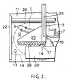
- Figure 2 is an underneath view in section on the line 2-2 of Figure 1.
- Referring to the drawings, a
printed circuit board 10 comprises arigid substrate 11 of electrically non-conductive material. The circuit board is of conventional construction and has, on one or both surfaces of the substrate, a pattern of electricallyconductive tracks 7 to provide interconnections between electronic components 8 forming an electronic circuit. The construction of printed circuit boards and the mounting of electronic components thereon to form electronic circuits is well known and hence it is considered unnecessary for an understanding of the present invention to describe such construction in detail. Astepper motor 12 is mounted on thesubstrate 11 and rigidly secured thereto by means ofscrews 13 engaging abase plate 14 of the motor. Electrical connections 9 are made between theconductive tracks 7 of the electronic circuit and terminals of the motor. For this purpose the motor may be provided with terminal pins which protrude through the substrate or it may be provided with flying leads which are connected to terminal pins secured in the substrate and connected to the conductive tracks. The motor has apower output shaft 15 extending through anaperture 16 in thesubstrate 11. Theshaft 15 projects beyond the face of the substrate and carries adrive pinion 17. Thepinion 17 engages anintermediate pinion 18 rotatably mounted on astub shaft 19. Thestub shaft 19 is secured to abracket 20 rigidly mounted on thesubstrate 11. The free end of the stub shaft engages in a further aperture in the substrate. Anoutput pinion 21 is formed integrally with theintermediate pinion 18 and rotates with the intermediate pinion. - The printed circuit substrate, with the motor and gear train mounted thereon, is mounted on a
frame 22 of a postal franking machine. This frame member carries an assembly of mechanical components whose function is the setting of print elements in a printing drum and then maintaining these elements in the required set position while a printing operation is effected by rotation of the drum. The constructional details of these components are not required for an understanding of the present invention and therefore it is considered to be unnecessary to describe in detail the construction of these mechanical components. Briefly, as shown in Figure 1, the franking machine hasrotatable printing elements 30 located in aprinting drum 31 carried on the end of ahollow shaft 23. The printing elements can be set into angular positions corresponding respectively to franking values to be printed. Each printing element has atoothed wheel 32 formed integrally therewith, or secured thereto, engaged by teeth on arack 33 which is movable longitudinally. Therack 33 is formed on one end of aselector bar 34 which extends through thehollow shaft 23 into the interior of theframe 22. Theselector bar 34, adjacent its other end, is engaged by anannular member 24 rotatable with thehollow shaft 23 and slidable along the shaft. The periphery of themember 24 engages in a groove in acarriage 25 slidable onguides shaft 23. Thecarriage 25 has a linear row ofteeth 28 with which the teeth of thepinion 21 mesh when thesubstrate 11 is mounted on theframe 22. It will be appreciated that rotation of thepinion 21 by thestepper motor 12 causes thecarriage 25 to move parallel to theshaft 23. This movement of the carriage causes theannular member 24 to slide along theshaft 23 and, due to its engagement with the selector bar, to move the selector bar longitudinally of the shaft and hence cause therack 33 to rotate thetoothed wheel 32 and theprinting element 30. Means not shown are provided to retain theprinting element 30 in a precise angular position during rotation of theprinting drum 31 by theshaft 23 such that it will effect printing of the desired value of franking. - By providing the gear train consisting of the
pinions - In order to control the motor such that the
printing element 30 is set to a required angular position it is necessary to provide a sensor operative to generate signals, or from which signals can be derived, indicative of the position of the print element. One form of such a sensor is described in the specification of British patent No. 2034991. The sensor comprises a pattern of conductive tracks in the form of concentric part circular segments so arranged and interconnected that as they are swept by rotatable contacts a "2 out of 5" code signal is derived which represents the angular position of the rotatable contacts. A sensor of this type is provided in the present embodiment byelectrical contacts 29 carried on a face of theintermediate pinion 18 adjacent the surface of the printed circuit board and concentric part circularconductive segments 35 formed by conductive tracks on the face of the substrate concentric with the axis of thestub shaft 19. Thus theintermediate pinion 18 serves not only to transmit mechanical torque from the motor to the slidable carriage but also carries the rotatable part of the angular position sensor. - As mentioned above, franking machines commonly are required to print franking values having up to four digits. Each printing element is formed to print a single digit and therefore four printing elements are provided each individually settable to a selected value. Thus although for clarity in the drawing only a single printing element and associated print setting elements and drive motor are shown, it is to be understood that a motor, gear train, sensor, carriage and selector bar are provided for each print element which it is desired to set to a selected position. Each motor, gear train and sensor with associated circuitry is carried on the one printed
circuit substrate 11. Theannular members 24 are disposed to slide along axially spaced portions of theshaft 23 and in order to achieve a compact construction thecarriages 25 engaging two of theannular members 24 are disposed to one side of theshaft 23 and the carriages engaging the other two annular members are disposed to the other side of theshaft 23. Asingle guide 26 may serve to support all four of the carriages whereas twoguides 27 may be provided, one to each side of theshaft 23, each supporting two of the carriages. - It will be appreciated that the construction described hereinbefore consists of a first module comprising a printed circuit board carrying electronic and electromechanical components and a second module comprising an assembly of mechanical components on which the printed circuit board of the first module is mounted. As a result the only operational interconnection required between the printed circuit board of the first module and the assembly of mechanical components comprising the second module is the meshing of the
pinion 21 with theteeth 28 on thecarriage 25. No electrical connections are needed between the modules. Thus the manufacture of the franking machine can be separated into two distinct operations, one being the assembly of mechanical components and the other being the assembly of electronic and electromechanical components. Furthermore when servicing of the machine becomes necessary access to the mechanical components is easily effected by removal of the first module. The electronic and electromechanical part of the machine forming the first module can be tested as an integral unit.
Claims (12)
Applications Claiming Priority (2)
| Application Number | Priority Date | Filing Date | Title |
|---|---|---|---|
| GB8607365 | 1986-03-25 | ||
| GB868607365A GB8607365D0 (en) | 1986-03-25 | 1986-03-25 | Electromechanical drives |
Publications (3)
| Publication Number | Publication Date |
|---|---|
| EP0239355A2 EP0239355A2 (en) | 1987-09-30 |
| EP0239355A3 EP0239355A3 (en) | 1988-07-06 |
| EP0239355B1 true EP0239355B1 (en) | 1992-03-04 |
Family
ID=10595196
Family Applications (1)
| Application Number | Title | Priority Date | Filing Date |
|---|---|---|---|
| EP87302505A Expired EP0239355B1 (en) | 1986-03-25 | 1987-03-24 | Electromechanical drives for franking machines |
Country Status (4)
| Country | Link |
|---|---|
| US (1) | US4735138A (en) |
| EP (1) | EP0239355B1 (en) |
| DE (1) | DE3776934D1 (en) |
| GB (1) | GB8607365D0 (en) |
Families Citing this family (34)
| Publication number | Priority date | Publication date | Assignee | Title |
|---|---|---|---|---|
| US4852479A (en) * | 1987-12-07 | 1989-08-01 | Pitney Bowes Inc. | Postage meter having a worm gear drive |
| US4846715A (en) * | 1987-12-21 | 1989-07-11 | Pitney Bowes Inc. | Postage meter voice coil motor printwheel setting assembly |
| GB9020596D0 (en) * | 1990-09-21 | 1990-10-31 | Alcatel Business Systems | Data transmission method and apparatus |
| US5445074A (en) * | 1994-11-02 | 1995-08-29 | Pitney Bowes Inc. | Value selection and printing apparatus including a security device |
| US5719381A (en) * | 1995-04-14 | 1998-02-17 | Ascom Hasler Mailing Systems Ag | Postage meter with hollow rotor axle |
| US8412377B2 (en) | 2000-01-24 | 2013-04-02 | Irobot Corporation | Obstacle following sensor scheme for a mobile robot |
| US8788092B2 (en) | 2000-01-24 | 2014-07-22 | Irobot Corporation | Obstacle following sensor scheme for a mobile robot |
| US6956348B2 (en) | 2004-01-28 | 2005-10-18 | Irobot Corporation | Debris sensor for cleaning apparatus |
| US6690134B1 (en) | 2001-01-24 | 2004-02-10 | Irobot Corporation | Method and system for robot localization and confinement |
| US7571511B2 (en) | 2002-01-03 | 2009-08-11 | Irobot Corporation | Autonomous floor-cleaning robot |
| US7429843B2 (en) | 2001-06-12 | 2008-09-30 | Irobot Corporation | Method and system for multi-mode coverage for an autonomous robot |
| US8396592B2 (en) | 2001-06-12 | 2013-03-12 | Irobot Corporation | Method and system for multi-mode coverage for an autonomous robot |
| US9128486B2 (en) | 2002-01-24 | 2015-09-08 | Irobot Corporation | Navigational control system for a robotic device |
| US8428778B2 (en) | 2002-09-13 | 2013-04-23 | Irobot Corporation | Navigational control system for a robotic device |
| US8386081B2 (en) | 2002-09-13 | 2013-02-26 | Irobot Corporation | Navigational control system for a robotic device |
| US7332890B2 (en) | 2004-01-21 | 2008-02-19 | Irobot Corporation | Autonomous robot auto-docking and energy management systems and methods |
| DE112005000738T5 (en) | 2004-03-29 | 2007-04-26 | Evolution Robotics, Inc., Pasadena | Method and device for determining position using reflected light sources |
| KR101214723B1 (en) | 2004-06-24 | 2012-12-24 | 아이로보트 코퍼레이션 | Remote control scheduler and method for autonomous robotic device |
| US8972052B2 (en) | 2004-07-07 | 2015-03-03 | Irobot Corporation | Celestial navigation system for an autonomous vehicle |
| US7706917B1 (en) | 2004-07-07 | 2010-04-27 | Irobot Corporation | Celestial navigation system for an autonomous robot |
| US8392021B2 (en) | 2005-02-18 | 2013-03-05 | Irobot Corporation | Autonomous surface cleaning robot for wet cleaning |
| ES2346343T3 (en) | 2005-02-18 | 2010-10-14 | Irobot Corporation | AUTONOMOUS SURFACE CLEANING ROBOT FOR DRY AND WET CLEANING. |
| US7620476B2 (en) | 2005-02-18 | 2009-11-17 | Irobot Corporation | Autonomous surface cleaning robot for dry cleaning |
| US8930023B2 (en) | 2009-11-06 | 2015-01-06 | Irobot Corporation | Localization by learning of wave-signal distributions |
| EP2829939B1 (en) | 2005-12-02 | 2019-11-13 | iRobot Corporation | Autonomous coverage robot navigation system |
| EP2816434A3 (en) | 2005-12-02 | 2015-01-28 | iRobot Corporation | Autonomous coverage robot |
| US8584305B2 (en) | 2005-12-02 | 2013-11-19 | Irobot Corporation | Modular robot |
| EP2533120B1 (en) | 2005-12-02 | 2019-01-16 | iRobot Corporation | Robot system |
| KR101300492B1 (en) | 2005-12-02 | 2013-09-02 | 아이로보트 코퍼레이션 | Coverage robot mobility |
| US8528157B2 (en) | 2006-05-19 | 2013-09-10 | Irobot Corporation | Coverage robots and associated cleaning bins |
| US8417383B2 (en) | 2006-05-31 | 2013-04-09 | Irobot Corporation | Detecting robot stasis |
| ES2559128T3 (en) | 2007-05-09 | 2016-02-10 | Irobot Corporation | Autonomous compact covering robot |
| JP5027735B2 (en) * | 2007-05-25 | 2012-09-19 | サッポロビール株式会社 | Method for producing sparkling alcoholic beverage |
| KR101497197B1 (en) | 2010-02-16 | 2015-02-27 | 아이로보트 코퍼레이션 | Vacuum brush |
Family Cites Families (4)
| Publication number | Priority date | Publication date | Assignee | Title |
|---|---|---|---|---|
| DE2745109A1 (en) * | 1977-10-07 | 1979-04-12 | Bosch Gmbh Robert | ELECTRIC MACHINE, IN PARTICULAR HAND TOOL MACHINE |
| IT7922514U1 (en) * | 1979-09-12 | 1981-03-12 | Star Utensili Elett S P A | MOUNTING ARRANGEMENT OF A CONTROL SWITCH IN AN ELECTRIC TOOL. |
| GB2079223B (en) * | 1980-07-09 | 1984-03-14 | Roneo Alcatel Ltd | Postal franking meter |
| US4441420A (en) * | 1982-12-08 | 1984-04-10 | Pitney Bowes | Envelope ejection mechanism for a mailing machine |
-
1986
- 1986-03-25 GB GB868607365A patent/GB8607365D0/en active Pending
-
1987
- 1987-03-23 US US07/028,754 patent/US4735138A/en not_active Expired - Lifetime
- 1987-03-24 DE DE8787302505T patent/DE3776934D1/en not_active Expired - Lifetime
- 1987-03-24 EP EP87302505A patent/EP0239355B1/en not_active Expired
Also Published As
| Publication number | Publication date |
|---|---|
| GB8607365D0 (en) | 1986-04-30 |
| EP0239355A3 (en) | 1988-07-06 |
| DE3776934D1 (en) | 1992-04-09 |
| US4735138A (en) | 1988-04-05 |
| EP0239355A2 (en) | 1987-09-30 |
Similar Documents
| Publication | Publication Date | Title |
|---|---|---|
| US4735138A (en) | Electromechanical drives for franking machines | |
| CA1089242A (en) | Electromechanical pulse-generator | |
| CA1155962A (en) | Printwheel homing apparatus | |
| US4195940A (en) | Line control for platen printing devices | |
| US4759283A (en) | Value selection mechanism for postal franking machines | |
| US4507526A (en) | Module unit time switch disk assembly | |
| US4723486A (en) | Device for automatic angular positioning of a plurality of indexable rotary machine elements, and a machine comprising a device of this type, especially a postal franking machine | |
| EP0139411B1 (en) | Device for controlling the rotary movement of a platen | |
| FI75064C (en) | ELEKTRONISKT STYRD FRANKERINGSMASKIN OCH FRISTAEMPLARE. | |
| GB2054937A (en) | Teleindicator for information boards | |
| US3518652A (en) | Remote meter reading attachment utilizing rotary switches | |
| US2818557A (en) | Digitizer | |
| US2886661A (en) | Electrical switching mechanism for intervalometer | |
| US4603238A (en) | Fast indexing encoder apparatus | |
| US2812170A (en) | Weighing apparatus | |
| US2935250A (en) | reppert | |
| US4313105A (en) | Encoding switches | |
| EP0225068A2 (en) | Electronic postage meter | |
| US4858174A (en) | Electronic postage meter control system employing a membrane switch mechanism | |
| US4236446A (en) | Check-digit printing means | |
| US4129815A (en) | Postal meter actuator | |
| US5628035A (en) | Moving body position detecting device | |
| CA1244370A (en) | Paper feed control in a printer | |
| GB2223575A (en) | Optical position encoder | |
| GB2154513A (en) | Improvements in or relating to a type carrying member |
Legal Events
| Date | Code | Title | Description |
|---|---|---|---|
| PUAI | Public reference made under article 153(3) epc to a published international application that has entered the european phase |
Free format text: ORIGINAL CODE: 0009012 |
|
| AK | Designated contracting states |
Kind code of ref document: A2 Designated state(s): DE FR GB |
|
| PUAL | Search report despatched |
Free format text: ORIGINAL CODE: 0009013 |
|
| AK | Designated contracting states |
Kind code of ref document: A3 Designated state(s): DE FR GB |
|
| 17P | Request for examination filed |
Effective date: 19881115 |
|
| RAP1 | Party data changed (applicant data changed or rights of an application transferred) |
Owner name: ALCATEL BUSINESS SYSTEMS LIMITED |
|
| 17Q | First examination report despatched |
Effective date: 19910605 |
|
| GRAA | (expected) grant |
Free format text: ORIGINAL CODE: 0009210 |
|
| AK | Designated contracting states |
Kind code of ref document: B1 Designated state(s): DE FR GB |
|
| REF | Corresponds to: |
Ref document number: 3776934 Country of ref document: DE Date of ref document: 19920409 |
|
| ET | Fr: translation filed | ||
| PLBE | No opposition filed within time limit |
Free format text: ORIGINAL CODE: 0009261 |
|
| STAA | Information on the status of an ep patent application or granted ep patent |
Free format text: STATUS: NO OPPOSITION FILED WITHIN TIME LIMIT |
|
| 26N | No opposition filed | ||
| REG | Reference to a national code |
Ref country code: GB Ref legal event code: 732E |
|
| REG | Reference to a national code |
Ref country code: FR Ref legal event code: CD |
|
| REG | Reference to a national code |
Ref country code: FR Ref legal event code: TP |
|
| REG | Reference to a national code |
Ref country code: GB Ref legal event code: IF02 |
|
| PGFP | Annual fee paid to national office [announced via postgrant information from national office to epo] |
Ref country code: FR Payment date: 20060313 Year of fee payment: 20 |
|
| PGFP | Annual fee paid to national office [announced via postgrant information from national office to epo] |
Ref country code: DE Payment date: 20060314 Year of fee payment: 20 |
|
| PGFP | Annual fee paid to national office [announced via postgrant information from national office to epo] |
Ref country code: GB Payment date: 20060322 Year of fee payment: 20 |
|
| PG25 | Lapsed in a contracting state [announced via postgrant information from national office to epo] |
Ref country code: GB Free format text: LAPSE BECAUSE OF EXPIRATION OF PROTECTION Effective date: 20070323 |