EP0238114B1 - Data display - Google Patents
Data display Download PDFInfo
- Publication number
- EP0238114B1 EP0238114B1 EP87200222A EP87200222A EP0238114B1 EP 0238114 B1 EP0238114 B1 EP 0238114B1 EP 87200222 A EP87200222 A EP 87200222A EP 87200222 A EP87200222 A EP 87200222A EP 0238114 B1 EP0238114 B1 EP 0238114B1
- Authority
- EP
- European Patent Office
- Prior art keywords
- display
- memory
- data
- processor
- background
- Prior art date
- Legal status (The legal status is an assumption and is not a legal conclusion. Google has not performed a legal analysis and makes no representation as to the accuracy of the status listed.)
- Expired - Lifetime
Links
- 238000000034 method Methods 0.000 claims description 32
- 239000013598 vector Substances 0.000 description 18
- 230000006872 improvement Effects 0.000 description 8
- RRLHMJHRFMHVNM-BQVXCWBNSA-N [(2s,3r,6r)-6-[5-[5-hydroxy-3-(4-hydroxyphenyl)-4-oxochromen-7-yl]oxypentoxy]-2-methyl-3,6-dihydro-2h-pyran-3-yl] acetate Chemical compound C1=C[C@@H](OC(C)=O)[C@H](C)O[C@H]1OCCCCCOC1=CC(O)=C2C(=O)C(C=3C=CC(O)=CC=3)=COC2=C1 RRLHMJHRFMHVNM-BQVXCWBNSA-N 0.000 description 7
- 238000010586 diagram Methods 0.000 description 6
- 239000003086 colorant Substances 0.000 description 4
- 238000013459 approach Methods 0.000 description 3
- 230000008901 benefit Effects 0.000 description 3
- 230000001788 irregular Effects 0.000 description 3
- 230000009286 beneficial effect Effects 0.000 description 2
- 230000000694 effects Effects 0.000 description 2
- 230000006870 function Effects 0.000 description 2
- 230000008569 process Effects 0.000 description 2
- 206010042618 Surgical procedure repeated Diseases 0.000 description 1
- 238000004458 analytical method Methods 0.000 description 1
- 125000004122 cyclic group Chemical group 0.000 description 1
- 238000013479 data entry Methods 0.000 description 1
- 230000003247 decreasing effect Effects 0.000 description 1
- 239000011159 matrix material Substances 0.000 description 1
- 239000000203 mixture Substances 0.000 description 1
- 238000012986 modification Methods 0.000 description 1
- 230000004048 modification Effects 0.000 description 1
- 230000000306 recurrent effect Effects 0.000 description 1
- 238000012546 transfer Methods 0.000 description 1
Images

Classifications
-
- G—PHYSICS
- G09—EDUCATION; CRYPTOGRAPHY; DISPLAY; ADVERTISING; SEALS
- G09G—ARRANGEMENTS OR CIRCUITS FOR CONTROL OF INDICATING DEVICES USING STATIC MEANS TO PRESENT VARIABLE INFORMATION
- G09G5/00—Control arrangements or circuits for visual indicators common to cathode-ray tube indicators and other visual indicators
- G09G5/36—Control arrangements or circuits for visual indicators common to cathode-ray tube indicators and other visual indicators characterised by the display of a graphic pattern, e.g. using an all-points-addressable [APA] memory
- G09G5/39—Control of the bit-mapped memory
- G09G5/393—Arrangements for updating the contents of the bit-mapped memory
Definitions
- the invention relates to a method of operating a display apparatus to display a moving object against a background on the screen of a display device, the screen display being in the form of discrete pixels or dots each of which has its colour and/or luminance defined by a respective digital code in a display memory of the apparatus at a location corresponding to the position of the pixel in the display, the apparatus including a processor for controlling digitally the storage, selection and display of data in the display memory.
- the invention further relates to digitally operable data display apparatus of a type for displaying as an entity on the screen of a CRT (cathode ray tube) or other display device a quantity of data which is represented by digital codes stored in a display memory.
- CTR cathode ray tube
- the display data can be, for example, a 320 x 250 resolution dot matrix colour display and in the case of raster scan display device the digital codes stored in the display memory are accessed repeatedly by the processor to update the display in a recurrent cycle of scanning lines which may be produced with or without interlaced field scanning.
- a problem that is encountered with such bit-map displays, as they are termed, is to produce real-time movement (or animation) of an object in the display under logic processor control, because the time available for plotting the object in one position, erasing it, re-plotting the background at that object position and then re-plotting the object at a new position, is very small.
- the cycle of logic operations which is required to move an object against a fixed background comprises:
- steps (i) and (iv) can involve a known technique of manipulating digital data for the smallest rectangular area of background which the object will fit into.
- steps (i) and (iv) can involve a known technique of manipulating digital data for the smallest rectangular area of background which the object will fit into.
- the object has an irregular shape, the digital data for more pixels than are strictly necessary has to be manipulated.
- the invention provides a method of displaying a moving object against a background as set forth in the opening paragraph characterised in that the method comprises converting the shape of the object before display of said moving object commences into at least one machine code program, storing the or each such program in a program memory of the processor and subsequently causing the processor to run the program to write into the appropriate locations of the display memory at machine code operating speed of the processor the digital codes which represent the object, and causing the display of the object as represented by the digital codes in the display memory on the screen of the display device.
- the method of the invention affords the advantage that since all the logic decisions on which to copy (or not to copy) to create the object are taken in advance, that is when the picture to be displayed is initially prepared rather than during the "animated" running of the picture, redundant (background) pixels do not have to be considered.
- the method of the invention allows advantage to be taken of any unique aspects in the hardware architecture of the processor used for the data display apparatus, for instance an architecture which allows a horizontal strip of pixels (say 4) to be copied using a single machine code instruction.
- the net improvement in the speed at which an object can be redefined at successive new positions (animated) in a display depends to a significant extent on the shape of the object.
- the improvement in speed is marginal in comparison with the aforesaid known technique used in an existing data display apparatus.
- the improvement in the speed of operation can be as much as 100 times.
- the method of the invention does, however, require much more computer memory for the machine code instructions than was hitherto required for the known technique and these instructions take some time to generate.
- the invention further provides data display apparatus for displaying on the screen of a display device display data in the form of discrete pixels or dots each of which has its colour and/or luminance defined by a respective digital code in a display memory of the apparatus at a location corresponding to the position of the pixel in the display, the apparatus including a processor for controlling digitally the storage, selection and display of data in the display memory and movement means for moving an object against a background in the display, said movement means comprising means for storing before display of said object commences in a program memory of the processor at least one machine code program specific to the shape of the object and means for causing the processor to run the machine code program to write into the appropriate locations of the display memory at machine code operating speed of the processor the digital codes which represent the object.
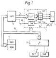
- the data display apparatus shown in Figure 1 comprises a display device 1, a display generator 2, a processor 3, a background memory 4, a display memory 5 and user interface apparatus 6 and 7.
- the display device is suitably a colour television monitor which is connected to receive R, G, B video signals from the display generator 2. These R, G, B video signals are produced in the display generator 2 by three digital-to-analogue converters 8, 9 and 10, respectively.
- the display generator 2 also includes a colour look-up table 11 which is a read/write memory and is responsive to dot information received from the display memory 5 over a bus 12 to produce digital signals for driving the converters 8, 9 and 10.
- a display timer 13 in the display generator 2 provides line and field synchronisation signals LS and FS for the television monitor 1 over a connection 14. The timer 13 also provides over a connection 15 timing signals T for controlling the transfer of dot information from the display memory 5 to the colour look-up table 11.
- the display memory 5 is a random-access memory which has a capacity for storing dot information for at least one display frame.
- the dot information comprises digital codes composed of one or more bits per dot to be displayed, depending on the range of colours afforded by the colour look-up table 11.
- a combined address/data bus 16 interconnects the display generator 2 and the display memory 5 with the processor 3.
- the background memory 4 which is also at least partially a random-access memory, is also connected to the address/data bus 16.
- the background memory 4 may also have a read-only memory part which contains permanent program data for controlling the "house-keeping" operations of the processor 3.
- the user interface apparatus comprises a keyboard data entry device 6 and a writing tablet 7. Such interface apparatus is well-known in the art and specific details thereof are unnecessary for a understanding of the present invention.
- the processor 3 can be a commercially available microprocessor, for instance, the Signetics S68000 »p.
- the writing tablet 7 By means of the writing tablet 7, a user draws a background for display on the screen of the display device 1.
- the writing tablet 7 can include a colour palette to enable a coloured background to be drawn.
- the background is displayed as it is being drawn and the digital codes for the pixels which form the display background are stored in the display memory 5. They may also be transferred to the background memory 4 for permanent storage. This process is well-known in the art, as are programmes for implementing it, and will not therefore be elaborated on.
- An 'animation' mode selection signal is now entered by the user. This mode gives the user the option of selecting one 'cell' size from a small selection of predetermined 'cell' sizes.
- the display screen is partitioned into fixed rectangles of that the selected 'cell' size.
- the user can now draw an object of any shape within the selected 'cell' size.
- the object is drawn in the rectangle in the top left-hand corner of the screen and subsequent versions of the object can then be generated automatically in successive other rectangles using a 'replicate' function.
- the 'replicate' function can be used in conjunction with writing tablet control to make appropriate modifications to the basic shape of the object.
- the objects are displayed as they are created.
- the digital codes for all the object shapes created are stored in the background memory 4.
- the animation facilities available to a user should also be able to specify that displayed objects should 'jump' apparently instantaneously from one position to another, and a user should also be able to specify that background should not be replaced after an object has been moved.
- This allows 'a growing pile of coins' effect to be achieved by initially displaying a 'coin' object at the base of the display and then causing the object to move (slowly) towards the top of the display without replacing the previous object copies by background to eliminate them during the progression.
- a user should also be able to produce 'a pile of coins' that changes shape as the pile grows, by progressively altering the shape of the object used for the pile.
- the facility to include a 'GOTO' instruction in a suitable programme sequence would enable a user to generate loops of continuous motion. Such a programme sequence might be:-
- the programme sequence would also include some form of loop counter to allow for the eventual termination of loops of motion.
- Fast moving objects would have the 'delay' set to 0, and x and y position co-ordinates would define only a few spaced-apart points along the vector.
- Slow moving objects would have the 'delay' set to appropriate non-zero values and the x and y position co-ordinates would define nearly adjacent pixels.
- the programme step "(10) struct. shape” is machine code sub-routine which is generated at run-time by a special 'shape compiler' programme from the specification of the cell for an object. The purpose of doing this is to use the 'shape compiler' programme before display commences when time is unimportant. The machine code is then run during display time to generate the data for the object shape in the display memory.
- the 'shape compiler' analyses the object data in the cells produced by a user and generates one machine code sub-routine for each object shape. These sub-routines all have the same specification and inspect in a first register TARGET the start address of the display memory location corresponding to the current vector point as identified by the relevant x posn and y posn co-ordinates.
- the sub-routines inspect the start address of the display memory locations corresponding to the previous current vector in the primary and secondary displays as identified by the relevant two pairs of x posn and y posn co-ordinates.
- Scan synchronisation is employed to ensure that writing operations for writing object shapes into the appropriate locations of the display memory do not clash with the cyclic read-out operations from the display memory for the actual display.
- the problem of achieving scan synchronisation is complicated by the fact that the processor has to write two sets of data into the display memory, that is, one set of data to replace the old background at a vector point where an object shape was previously displayed and a second set of data to redefine the object shape at a new vector point.
- the first case one should wait for the scan to pass the new object and plot that, and then ensure that the scan has passed the old object before erasing it with the background.
- the second case one must reverse the process.
- the third case one need only wait for the lowest of the two cells to be passed.
- the fourth case one must be careful to ensure that the old background is replaced before the new object is written.
- the fifth case is easy because only one cell has to be written.
- the compiler could (in principle) calculate the time taken to write the shape and only wait long enough to ensure that display reads and processor writes do not overtake one another. This should mean that one need only wait until the scan has passed (say) halfway down the object before starting to write - being sure that it will have moved on far enough to reach the bottom of the object before the processor. This will have a particularly beneficial effect for short, wide objects where the processor is working much slower than the display system. All this data needs to be compiled into a movement code.
- Object shape coding will be with a mixture of instructions, some using literal data encoded into the instruction, and some being read out of data areas. Where long runs of identical pixels occur 'MOVEML' instructions may be used to advantage and 'holes' or transparent areas of the object should take up little or no code space and execution time.
- the cell required for this letter group PRL comprises approximately a 70 x 40 pixel rectangle with a fair degree of emptyness and some very short runs. Note that some of these runs are of odd length: this can be achieved with the 68000 processor addressing modes but requires more byte-wide operations.
- the first three rows of this object cell may be compiled as follows into likely (but not 100% optimal) machine code: it is assumed that an address register A0 points initially at the display memory address for the top-left-hand pixel. The sequence above takes the following amount of time:- Row No. CPU Clock Periods Program reads Display writes 1 12 21 18 2 12 22 20 3 20 17 9 total 44 60 47
- a worst case situation for a display access is when the processor attempts to write a pixel or pair of pixels during the active line time. Under these circumstances the processor will be held in a wait state for at most 8 clock periods and the access itself can take a further 8 clock periods (this includes the VME bus overhead).
- the display subsystem clock runs at 13.5 MHz so that an access during the 52 »s active line time could take as long as 1.2 »s. During the 12 »s line blanking period and during the whole of frame blanking the worst case access of 0.6 »s.
- the time taken to redraw the background will be roughly two MOVEML instructions for every (approx) 40 pixels horizontally, plus to ADD instructions at the end of each line - All of this must then be multiplied by the number of pixels vertically.
- a total of 482 instruction reads + 3,200 CPU clock periods + 6,400 display read/write operations. This make a total of 641 »s of processor + 7,040 »s of display access time for the MOVEML's plus 160 instruction reads ( 20 »s) for the ADD's.
- the overriding criterion for speed seems to be the time taken to actually access the display memory, so decreasing the number of pixels read/written from there would be beneficial.
- the only possible optimisation could be from the background replacement operation. As can be seen from the calculations above, most time, at least in the example given, is spent in re-writing the background for the object.
- Another possibility would be to write the object shape out from right to left, using auto-decrement instructions to move the address register, in which case very long runs might be made more efficient both in time and memory usage by use of the MOVEML instruction, although this would require more registers for storing colour data if the previous optimisation were employed.
- the object compiler really only needs to standardize the width of objects so that the MOVEML instruction may be used efficiently to replace the background. Matters could also be improved by taking the actual height of the object into consideration when re-writing the background.
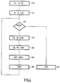
- Figure 3 is a flow diagram illustrating a method of displaying a moving object against a fixed background.
- the first step, shown in box 100 (GEN.CHAR.SHPS.), of the method is to generate one or more object or character shapes. These shapes are then converted into a machine code program, box 101 (CON.MAC.CDS) and the machine code program for each shape is stored in the background memory, box 102 (ST).
- a background scene against which the motion is to be effected is generated, box 103 (GEN.BKGD) and stored.
- the generation of the object shapes and background may be effected by the user with the aid of the interface apparatus 6 and 7 which could also include apparatus for digitising real scenes for background use, for example originating from video tape or video disc players.
- the user specifies the motion of the object or character, box 104 (SPEC. CHAR/MOT). This will include the start and stop positions, the speed of motion and the vectors along which the motion is to take place.
- This information is compiled, box 105 (COMP), by combining the selected shape(s), background, and motion.
- This compiled sequence is then fed to the RAM5 to be passed to the display screen to enable the sequence to be viewed, box 106 (VW.SEQ.).
- Figure 4 illustrates in greater detail the steps represented by boxes 104 to 106 in Figure 3.
- Box 200 (SEL.IN.SHP) represents the selection of a particular object which is to be moved against the fixed background and box 201 (SEL.IN.POSN) represents the setting of the initial position of the object.
- a decision, box 202 (ENDSEQ?), is then taken as to whether the movement sequence has been completed. If not, then the next object position is specified, box 203 (SEL.NX.POSN) and the next object shape is also specified, box 204 (SEL.NX.CHAR).
- the object shape and object position may both be changed or one of the shape and position may be kept constant with the other changed.
- next step of the method is to generate the code for replacing the background where the object was last displayed, box 205 (REP.BKGD), followed by the step of compiling the code required to enable the information defining that picture of the sequence to be entered into the display memory and storing the compiled code in the background memory, box 206 (COMP).
- the decision, box 202, as to whether the motion sequence has ended is again taken and the procedure repeated until the end of the sequence of pictures is reached.
- the user can call up the compiled code which represents the series of pictures, box 207 (DISP).
- the compiled code causes each picture of the sequence to be generated and stored in the display memory (RAM5) in turn to enable the sequence of pictures to be displayed on the display device 1.
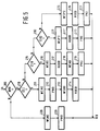
- Figure 5 illustrates the scan synchronisation techiques discussed hereinbefore.
- This sequence is entered at A from box 204 (SEL.NX.CHAR) shown in Figure 4 and starts with a decision as to whether background replacement is required, box 209 (BRR?). If background replacement is required then a decision is made as to whether the new character position gives rise to CASE I, box 210 (CS.1?). If it does then the next step is to wait until the scan has passed the new object position, box 211 (WSNO). The new object is then written into the appropriate part of the RAM5, box 212 (PNO.). The next step is to wait until the scan has passed the old object position, box 213 (WSOO). The old object is then replaced by the background which had previously been stored, box 214 (ROOB). The exit B re-enters Figure 4 at the input of decision box 202.
- CASE II is applicable, box 215 (CS.II?). If this is so then the next step is to wait until the scan has passed the old object, box 216 (WSOO) and then to replace the old object by the background which had previously been stored, box 217 (ROOB). The next step is to wait until the scan has passed the position of the new object, box 218 (WSNO) and then write the new object into the appropriate part of the RAM5, box 219 (PNO).
- box 220 If it is determined that the new object position gives rise to CASE III, box 220 (CS.III?), then the next step is to wait for the scan to pass the position of the lowest of the old and new objects, box 221 (WSPO). Then the old object is replaced by the background, box 222 (ROOB), and the new object is written in to the appropriate part of the RAM5, box 223 (PNO).
- the first step is then to wait for the scan to pass the position of the lowest of the old and new object positions, box 225 (WSPO).
- the old object is then replaced by the background, box 226 (ROOB) and the new object written into the appropriate part of the RAM5, box 227 (PNO).
Landscapes
- Engineering & Computer Science (AREA)
- Physics & Mathematics (AREA)
- Computer Hardware Design (AREA)
- General Physics & Mathematics (AREA)
- Theoretical Computer Science (AREA)
- Processing Or Creating Images (AREA)
- Controls And Circuits For Display Device (AREA)
- Image Generation (AREA)
Description
- The invention relates to a method of operating a display apparatus to display a moving object against a background on the screen of a display device, the screen display being in the form of discrete pixels or dots each of which has its colour and/or luminance defined by a respective digital code in a display memory of the apparatus at a location corresponding to the position of the pixel in the display, the apparatus including a processor for controlling digitally the storage, selection and display of data in the display memory.
- The invention further relates to digitally operable data display apparatus of a type for displaying as an entity on the screen of a CRT (cathode ray tube) or other display device a quantity of data which is represented by digital codes stored in a display memory.
- The display data can be, for example, a 320 x 250 resolution dot matrix colour display and in the case of raster scan display device the digital codes stored in the display memory are accessed repeatedly by the processor to update the display in a recurrent cycle of scanning lines which may be produced with or without interlaced field scanning.
- A problem that is encountered with such bit-map displays, as they are termed, is to produce real-time movement (or animation) of an object in the display under logic processor control, because the time available for plotting the object in one position, erasing it, re-plotting the background at that object position and then re-plotting the object at a new position, is very small.
- The cycle of logic operations which is required to move an object against a fixed background comprises:-
- (i) reading out from the relevant memory locations in the display memory the digital data for an area of background corresponding to a new position where the object is to be moved to and storing this data elsewhere to save it,
- (ii) writing into the display memory at the vacated memory locations the digital data defining the shape of the object, with residual background, if any,
- (iii) waiting at least one frame (refresh) period to allow the object to be displayed at the new position,
- (iv) replacing the digital data for the area of background in its original memory locations in the display memory to "cancel" the object at the position,
- (v) computing the next position for the object.
- In existing data display apparatus, steps (i) and (iv) can involve a known technique of manipulating digital data for the smallest rectangular area of background which the object will fit into. Thus, if the object has an irregular shape, the digital data for more pixels than are strictly necessary has to be manipulated.
- It is preferable to do this because the computing time which is necessary to perform the logic decision for deciding to copy or not a pixel is usually longer than the computing time actually required to perform the copy. However, existing systems cannot avoid performing this logic decision for step (ii) in order to enter any residual background in the rectangular space occupied by the object.
- It is an object of the present invention to provide an improved method of moving an object against a fixed background in a data display apparatus.
- The invention provides a method of displaying a moving object against a background as set forth in the opening paragraph characterised in that the method comprises converting the shape of the object before display of said moving object commences into at least one machine code program, storing the or each such program in a program memory of the processor and subsequently causing the processor to run the program to write into the appropriate locations of the display memory at machine code operating speed of the processor the digital codes which represent the object, and causing the display of the object as represented by the digital codes in the display memory on the screen of the display device.
- By having this facility of generating this machine code program automatically from the object as initially display using, say, a writing tablet, a user can produce the machine code program without the need to be a programmer.
- The method of the invention affords the advantage that since all the logic decisions on which to copy (or not to copy) to create the object are taken in advance, that is when the picture to be displayed is initially prepared rather than during the "animated" running of the picture, redundant (background) pixels do not have to be considered.
- Additionally, the method of the invention allows advantage to be taken of any unique aspects in the hardware architecture of the processor used for the data display apparatus, for instance an architecture which allows a horizontal strip of pixels (say 4) to be copied using a single machine code instruction.
- The net improvement in the speed at which an object can be redefined at successive new positions (animated) in a display depends to a significant extent on the shape of the object. For an object having a simple rectangular shape, the improvement in speed is marginal in comparison with the aforesaid known technique used in an existing data display apparatus. However, for objects of highly complex shapes with holes and irregular outlines, it has been found that the improvement in the speed of operation can be as much as 100 times. The method of the invention does, however, require much more computer memory for the machine code instructions than was hitherto required for the known technique and these instructions take some time to generate.
- It is mentioned that alternative known methods of improving the speed of operation of real-time animation in a data display device use a hardware-only approach with either a special processor instruction called a "raster-op" or a dedicated piece of hardware called a "bit-blitter". However, both these known methods are only methods for speeding-up the rectangular area copy and will therefore still be slow compared with the method of the present invention when dealing with irregular shaped objects.
- The invention further provides data display apparatus for displaying on the screen of a display device display data in the form of discrete pixels or dots each of which has its colour and/or luminance defined by a respective digital code in a display memory of the apparatus at a location corresponding to the position of the pixel in the display, the apparatus including a processor for controlling digitally the storage, selection and display of data in the display memory and movement means for moving an object against a background in the display, said movement means comprising means for storing before display of said object commences in a program memory of the processor at least one machine code program specific to the shape of the object and means for causing the processor to run the machine code program to write into the appropriate locations of the display memory at machine code operating speed of the processor the digital codes which represent the object.
- In further considering the nature of the invention, reference will now be made by way of example to the accompanying drawings of which:-
- Figure 1 shows a block diagram of a data display apparatus in which the present invention can be embodied;
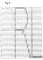
- Figure 2 illustrates an object which is to be moved against a fixed background;
- Figure 3 is a flow diagram illustrating a method of displaying a moving object according to the invention and which may be implemented in apparatus as shown in Figure 1;
- Figure 4 is a flow diagram showing part of the diagram of Figure 3 in greater detail; and
- Figure 5 is a flow diagram illustrating a scan synchronisation technique which may be included in the method according to the invention.
- Referring to the drawings, the data display apparatus shown in Figure 1 comprises a
display device 1, adisplay generator 2, aprocessor 3, a background memory 4, adisplay memory 5 anduser interface apparatus display generator 2. These R, G, B video signals are produced in thedisplay generator 2 by three digital-to-analogue converters 8, 9 and 10, respectively. Thedisplay generator 2 also includes a colour look-up table 11 which is a read/write memory and is responsive to dot information received from thedisplay memory 5 over abus 12 to produce digital signals for driving the converters 8, 9 and 10. Adisplay timer 13 in thedisplay generator 2 provides line and field synchronisation signals LS and FS for thetelevision monitor 1 over aconnection 14. Thetimer 13 also provides over aconnection 15 timing signals T for controlling the transfer of dot information from thedisplay memory 5 to the colour look-up table 11. - The
display memory 5 is a random-access memory which has a capacity for storing dot information for at least one display frame. The dot information comprises digital codes composed of one or more bits per dot to be displayed, depending on the range of colours afforded by the colour look-up table 11. A combined address/data bus 16 interconnects thedisplay generator 2 and thedisplay memory 5 with theprocessor 3. The background memory 4, which is also at least partially a random-access memory, is also connected to the address/data bus 16. The background memory 4 may also have a read-only memory part which contains permanent program data for controlling the "house-keeping" operations of theprocessor 3. The user interface apparatus comprises a keyboarddata entry device 6 and awriting tablet 7. Such interface apparatus is well-known in the art and specific details thereof are unnecessary for a understanding of the present invention. Theprocessor 3 can be a commercially available microprocessor, for instance, the Signetics S68000 »p. - Consider now the performance of the method according to the invention in displaying an animated object on a standard background.
- By means of the
writing tablet 7, a user draws a background for display on the screen of thedisplay device 1. Thewriting tablet 7 can include a colour palette to enable a coloured background to be drawn. The background is displayed as it is being drawn and the digital codes for the pixels which form the display background are stored in thedisplay memory 5. They may also be transferred to the background memory 4 for permanent storage. This process is well-known in the art, as are programmes for implementing it, and will not therefore be elaborated on. - An 'animation' mode selection signal is now entered by the user. This mode gives the user the option of selecting one 'cell' size from a small selection of predetermined 'cell' sizes.
- Once the selection has been made the display screen is partitioned into fixed rectangles of that the selected 'cell' size.
- The user can now draw an object of any shape within the selected 'cell' size. Conveniently, the object is drawn in the rectangle in the top left-hand corner of the screen and subsequent versions of the object can then be generated automatically in successive other rectangles using a 'replicate' function. The 'replicate' function can be used in conjunction with writing tablet control to make appropriate modifications to the basic shape of the object. The objects are displayed as they are created. The digital codes for all the object shapes created are stored in the background memory 4.
- Before a sequence of object shapes as thus created and stored can be displayed to show animation the sequence must first be 'compiled'. This requires the user to specify the initial display position, final display position and duration of each direction vector that the object is to move along, and to specify which set of the pre-drawn 'cells' is to be used for each vector.
- In a particular embodiment of the invention using a processor in the 68000 series, the following limitations as to cell size and position are dictated by the 68000 instruction set:-
- (i) cells must be some multiple of 2 pixels in width.
- (ii) cells can only be plotted at even horizontal pixel boundaries.
- (iii) cells are restricted in size as determined by the amount of data that can be copied in one frame period.
- However, using a processor in the 68020 series should eliminate restrictions (i) and (ii) and allow an increase in cell size as specified in (iii) as the 68020 series have a more flexible instruction set and wider buses.
- The animation facilities available to a user should also be able to specify that displayed objects should 'jump' apparently instantaneously from one position to another, and a user should also be able to specify that background should not be replaced after an object has been moved. This allows 'a growing pile of coins' effect to be achieved by initially displaying a 'coin' object at the base of the display and then causing the object to move (slowly) towards the top of the display without replacing the previous object copies by background to eliminate them during the progression. A user should also be able to produce 'a pile of coins' that changes shape as the pile grows, by progressively altering the shape of the object used for the pile. The facility to include a 'GOTO' instruction in a suitable programme sequence would enable a user to generate loops of continuous motion. Such a programme sequence might be:-
- 1. struct. vector(s) = determine the direction and limits of object movement along a selected vector.
- 2. int. number of posns. = indicate the number of points along the vector at which the object is to be displayed.
- 3. int. x posn = these two instructions indicate the
- 4. int. y posn co-ordinates of each object display point along the vector.
- 5. int. delay = indicate the number of display frames at which the object is held at each point.
- 6. int. leave background? = this is a decision to replace or not the background at the previous point at which the object was displayed.
- 7. vector list = indicates which vectors are available for execution.
- 8. struct. vector GOTO = this specifies which vector in the "vector list" is to be executed next.
- 9. cur. shape = this indicates which object shape is to be displayed at the current vector point.
- 10. struct. shape = this is a machine code operation for forming the shape of objects in accordance with the invention. This machine code operation is dealt with more fully below.
- The programme sequence would also include some form of loop counter to allow for the eventual termination of loops of motion. Fast moving objects would have the 'delay' set to 0, and x and y position co-ordinates would define only a few spaced-apart points along the vector. Slow moving objects would have the 'delay' set to appropriate non-zero values and the x and y position co-ordinates would define nearly adjacent pixels.
- The programme step "(10) struct. shape" is machine code sub-routine which is generated at run-time by a special 'shape compiler' programme from the specification of the cell for an object. The purpose of doing this is to use the 'shape compiler' programme before display commences when time is unimportant. The machine code is then run during display time to generate the data for the object shape in the display memory. The 'shape compiler' analyses the object data in the cells produced by a user and generates one machine code sub-routine for each object shape. These sub-routines all have the same specification and inspect in a first register TARGET the start address of the display memory location corresponding to the current vector point as identified by the relevant x posn and y posn co-ordinates. In second and third registers PBACKGROUND and SBACKGROUND the sub-routines inspect the start address of the display memory locations corresponding to the previous current vector in the primary and secondary displays as identified by the relevant two pairs of x posn and y posn co-ordinates.
- Scan synchronisation is employed to ensure that writing operations for writing object shapes into the appropriate locations of the display memory do not clash with the cyclic read-out operations from the display memory for the actual display. The problem of achieving scan synchronisation is complicated by the fact that the processor has to write two sets of data into the display memory, that is, one set of data to replace the old background at a vector point where an object shape was previously displayed and a second set of data to redefine the object shape at a new vector point.
- One solution to this scan synchronisation problem is to wait for the display read-out cycle to read past the bottom-most line of an area where an object shape is to be re-written. This will be either the bottom line of the new object shape if the object is moving down the screen, or the bottom line of the old shape if the object is moving up the screen. However, this solution may not be adequate if the object is moving rapidly in a vertical direction from top to bottom because re-writing the background at the top of the screen cannot be started until the display scan has reached the bottom of the screen.
- It is possible to distinguish five cases:
- CASE I :
- Upward movement by more than the height of the cell,
- CASE II :
- Downward movement by more then the height of the cell (both I & II could have a horizontal component),
- CASE III:
- Sideways movement of more than the width of the cell but with a vertical component less than or equal to the height of the cell.
- CASE IV :
- Small movements which result in the new cell overlapping.
- CASE V :
- Background replacement not required.
- In the first case one should wait for the scan to pass the new object and plot that, and then ensure that the scan has passed the old object before erasing it with the background. In the second case one must reverse the process. In the third case one need only wait for the lowest of the two cells to be passed. In the fourth case one must be careful to ensure that the old background is replaced before the new object is written. The fifth case is easy because only one cell has to be written.
- In addition the compiler could (in principle) calculate the time taken to write the shape and only wait long enough to ensure that display reads and processor writes do not overtake one another. This should mean that one need only wait until the scan has passed (say) halfway down the object before starting to write - being sure that it will have moved on far enough to reach the bottom of the object before the processor. This will have a particularly beneficial effect for short, wide objects where the processor is working much slower than the display system. All this data needs to be compiled into a movement code.
- In order to erase the last picture of the object, a standard sized block of background from the place pointed at by the register SBACKGROUND is copied to the place pointed at by the register PBACKGROUND. This may be performed with a fixed sequence of 'MOVEML' instructions of a 68000 series processor because it has already been specified that each cell will start on an even x address and will be some multiple of 4 bytes across.
- Object shape coding will be with a mixture of instructions, some using literal data encoded into the instruction, and some being read out of data areas. Where long runs of identical pixels occur 'MOVEML' instructions may be used to advantage and 'holes' or transparent areas of the object should take up little or no code space and execution time.
- In order to give an example let it be assumed that the group of letters 'PRL' is to be animated, with each letter drawn in a different colour. Using the
symbols - The cell required for this letter group PRL comprises approximately a 70 x 40 pixel rectangle with a fair degree of emptyness and some very short runs. Note that some of these runs are of odd length: this can be achieved with the 68000 processor addressing modes but requires more byte-wide operations. The first three rows of this object cell may be compiled as follows into likely (but not 100% optimal) machine code: it is assumed that an address register A0 points initially at the display memory address for the top-left-hand pixel.


The sequence above takes the following amount of time:-Row No. CPU Clock Periods Program reads Display writes 1 12 21 18 2 12 22 20 3 20 17 9 total 44 60 47 - Assuming no interrupts and nil-wait-state program memory there is a total of 284 clock periods plus the time taken to write 47 words into display memory since each program read takes four clock cycles. Assuming these three lines to be typical (a pessimistic assumption) then the entire 43 line object would take 4,000 clock periods plus 670 display memory cycles.
- With an 8 Mhz 68000 processor the programme memory component takes up 500 »s but the time taken for the display cycles may not be easy to determine due to the VME bus overhead and the statistical nature of processor access/display access collisions. A worst case situation for a display access is when the processor attempts to write a pixel or pair of pixels during the active line time. Under these circumstances the processor will be held in a wait state for at most 8 clock periods and the access itself can take a further 8 clock periods (this includes the VME bus overhead). The display subsystem clock runs at 13.5 MHz so that an access during the 52 »s active line time could take as long as 1.2 »s. During the 12 »s line blanking period and during the whole of frame blanking the worst case access of 0.6 »s.
- The improved access times during frame blanking will be ignored for the moment because drawing will be scan-synchronised and most accesses will therefore be during normal display lines. This gives a likely average access time of

Thus 670 display cycles will take of the order to 740 »s giving a total time for drawing the object shape of 1,240 »s. - The time taken to redraw the background will be roughly two MOVEML instructions for every (approx) 40 pixels horizontally, plus to ADD instructions at the end of each line - All of this must then be multiplied by the number of pixels vertically. For the example object shape this means 160 MOVEML's plus 80 ADD's. A total of 482 instruction reads + 3,200 CPU clock periods + 6,400 display read/write operations. This make a total of 641 »s of processor + 7,040 »s of display access time for the MOVEML's plus 160 instruction reads (= 20 »s) for the ADD's.
- This object can thus be rewritten against any background in approximately 9 ms. Assuming that the scan synchronisation takes negligible time and works sufficiently well then it may be predicted that objects up to about twice this size could be animated. (150 pixels by 40 or 70 by 80 pixels).
- Using a 10 MHz processor rather than an 8 MHz processor will not improve the speed of display cycles but will speed up processor and instruction read operations. This means that the 9 ms. redraw time given above could be reduced by about 250 »s. a 2 to 3% improvement!
- The overriding criterion for speed seems to be the time taken to actually access the display memory, so decreasing the number of pixels read/written from there would be beneficial. However, since all the pixels for the object shape itself must be re-written, the only possible optimisation could be from the background replacement operation. As can be seen from the calculations above, most time, at least in the example given, is spent in re-writing the background for the object.
- One could (for some object shapes) only replace the background in those pixels that were actually changed. This would mean compiling a code sequence similar to the one used for writing the object except that the pixel colour information would have to be read from a second display memory instead of being built into the code itself. This approach is only of use when, as in the example above, the object itself has many 'holes'. A very clever compiler should examine both possibilities and choose the fastest approach on a shape-by-shape basis.
- One could optimise the object writing sequence still further by noting the contents of the registers after one row of dots has been processed so that reloading them is unnecessary when a run of one colour is followed by a gap and then a run of some other colour.
- In addition, use could be made of more registers to remember more of the colours involved so that some improvement could be expected for patterns with less than, say, 8 colours. This might produce a 1% or 2% improvement in performance for some objects.
- Another possibility would be to write the object shape out from right to left, using auto-decrement instructions to move the address register, in which case very long runs might be made more efficient both in time and memory usage by use of the MOVEML instruction, although this would require more registers for storing colour data if the previous optimisation were employed.
- A doubling of performance could be achieved by only animating on a field-by-field basis. This would mean only writing to every alternate line of the display memory. It might also mean forcing the motion of the cell to steps of two pixels vertically which might look jerky for very slow speed motion. A more complex sequence of events as follows would be needed for alternate field animation:-


- One could re-calculate the co-ordinates of the object between fields to overcome the jerky nature of slow-speed motion but this might have unfortunate effects if the object is moving at speeds around 2 pixels per frame because only the even numbered lines of the object would ever be seen. This corresponds to an object which would travel the height of the screen in 11.5 seconds which is probably much slower than one is likely to be concerned about.
- Although the user would be required to fit the object shape into one of a range of standard sized cells, the object compiler really only needs to standardize the width of objects so that the MOVEML instruction may be used efficiently to replace the background. Matters could also be improved by taking the actual height of the object into consideration when re-writing the background.
- If the horizontal resolution of an object could be reduced by a factor two so that all runs of identical pixels were of even length, then every run would start on an even boundary and there would never by any need to generate wasteful MOVEB instructions at the start and end of sequences that are either of odd length, or worse, that the start on an odd byte boundary.
- Where an immediate MOVEB instruction is followed by another immediate MOVEB instruction, when there is a run of one colour ending on an odd byte boundary, followed by a run in a different colour, this would be optimised to an immediate MOVEW instruction. This would improve performance only marginally for simple objects or objects with many holes but would show a reasonable improvement for complex, multi-coloured objects.
- With these improvements one could perhaps hope to animate 120 x 100 pixel objects smoothly and without flicker, bearing in mind that the shape of the object can be changed on a frame-by-frame basis. The speed of the technique depends very heavily on the complexity of the object that is being animated. An object with big 'holes' in it can be much larger than a dense, multi-coloured object.
- Figure 3 is a flow diagram illustrating a method of displaying a moving object against a fixed background. The first step, shown in box 100 (GEN.CHAR.SHPS.), of the method is to generate one or more object or character shapes. These shapes are then converted into a machine code program, box 101 (CON.MAC.CDS) and the machine code program for each shape is stored in the background memory, box 102 (ST). A background scene against which the motion is to be effected is generated, box 103 (GEN.BKGD) and stored. The generation of the object shapes and background may be effected by the user with the aid of the
interface apparatus - Figure 4 illustrates in greater detail the steps represented by
boxes 104 to 106 in Figure 3. Box 200 (SEL.IN.SHP) represents the selection of a particular object which is to be moved against the fixed background and box 201 (SEL.IN.POSN) represents the setting of the initial position of the object. A decision, box 202 (ENDSEQ?), is then taken as to whether the movement sequence has been completed. If not, then the next object position is specified, box 203 (SEL.NX.POSN) and the next object shape is also specified, box 204 (SEL.NX.CHAR). Clearly the object shape and object position may both be changed or one of the shape and position may be kept constant with the other changed. In each case the next step of the method is to generate the code for replacing the background where the object was last displayed, box 205 (REP.BKGD), followed by the step of compiling the code required to enable the information defining that picture of the sequence to be entered into the display memory and storing the compiled code in the background memory, box 206 (COMP). The decision,box 202, as to whether the motion sequence has ended is again taken and the procedure repeated until the end of the sequence of pictures is reached. When the sequence has been compiled and stored the user can call up the compiled code which represents the series of pictures, box 207 (DISP). The compiled code causes each picture of the sequence to be generated and stored in the display memory (RAM5) in turn to enable the sequence of pictures to be displayed on thedisplay device 1. - Figure 5 illustrates the scan synchronisation techiques discussed hereinbefore. This sequence is entered at A from box 204 (SEL.NX.CHAR) shown in Figure 4 and starts with a decision as to whether background replacement is required, box 209 (BRR?). If background replacement is required then a decision is made as to whether the new character position gives rise to CASE I, box 210 (CS.1?). If it does then the next step is to wait until the scan has passed the new object position, box 211 (WSNO). The new object is then written into the appropriate part of the RAM5, box 212 (PNO.). The next step is to wait until the scan has passed the old object position, box 213 (WSOO). The old object is then replaced by the background which had previously been stored, box 214 (ROOB). The exit B re-enters Figure 4 at the input of
decision box 202. - If it is determined that the new character position does not give rise to CASE I, then a decision as to whether CASE II is applicable, box 215 (CS.II?). If this is so then the next step is to wait until the scan has passed the old object, box 216 (WSOO) and then to replace the old object by the background which had previously been stored, box 217 (ROOB). The next step is to wait until the scan has passed the position of the new object, box 218 (WSNO) and then write the new object into the appropriate part of the RAM5, box 219 (PNO).
- If it is determined that the new object position gives rise to CASE III, box 220 (CS.III?), then the next step is to wait for the scan to pass the position of the lowest of the old and new objects, box 221 (WSPO). Then the old object is replaced by the background, box 222 (ROOB), and the new object is written in to the appropriate part of the RAM5, box 223 (PNO).
- If background replacement is required and the object movement does not give rise to any of CASES I, II and III then it must give rise to CASE IV. The first step is then to wait for the scan to pass the position of the lowest of the old and new object positions, box 225 (WSPO). The old object is then replaced by the background, box 226 (ROOB) and the new object written into the appropriate part of the RAM5, box 227 (PNO).
- It should be noted that in CASE IV it is necessary to replace the old object with the background before writing the new object whereas in CASE III it is immaterial in which order these two steps are taken.
- If background replacement is not required (CASE V) then all that is required is to wait for the scan to pass the new object position, box 228 (WSNO), and then to write the new object into the appropriate part of the RAM5, box 229 (PNO).
Claims (10)
- A method of operating a display apparatus to display a moving object against a background on the screen of a display device, the screen display being in the form of discrete pixels or dots each of which has its colour and/or luminance defined by a respective digital code in a display memory of the apparatus at a location corresponding to the position of the pixel in the display, the apparatus including a processor for controlling digitally the storage, selection and display of data in the display memory, characterised in that the method comprises converting the shape of the object before display of said moving object commences into at least one machine code program, storing the or each such program in a program memory of the processor and subsequently causing the processor to run the program to write into the appropriate locations of the display memory at machine code operating speed of the processor the digital codes which represent the object, and causing the display of the object as represented by the digital codes in the display memory on the screen of the display device.
- A method as claimed in Claim 1, comprising creating the object shape on the display screen with a writing tablet or other user interface means and using a compiler programme to generate the machine code program from data defining the object shape.
- A method as claimed in Claim 1 or Claim 2, using a scan synchronisation technique to avoid conflict between read-out from the display memory for the display and writing into the display memory the data for both "new" object shapes and background areas which replace "old" object shapes.
- A method as claimed in any preceding Claim, wherein the animation of an object shape is achieved on a field-by-field basis comprising writing only to memory locations in the display memory that correspond to alternate display lines.
- A method as claimed in any of Claims 1 to 4 further comprising re-writing background data into the display memory in locations from which the moving object has moved.
- A method as claimed in Claim 5 comprising re-writing the background data only into locations in the display memory defining the shape and position of the moving object in the previous display frame.
- Data display apparatus for displaying on the screen of a display device display data in the form of discrete pixels or dots each of which has its colour and/or luminance defined by a respective digital code in a display memory of the apparatus at a location corresponding to the position of the pixel in the display, the apparatus including a processor for controlling digitally the storage, selection and display of data in the display memory and movement means for moving an object against a background in the display, said movement means comprising means for storing before display of said object commences in a program memory of the processor at least one machine code program specific to the shape of the object and means for causing the processor to run the machine code program to write into the appropriate locations of the display memory at machine code operating speed of the processor the digital codes which represent the object.
- Data display apparatus as claimed in Claim 7, comprising a compiler program for generating the machine code program to be stored from data generated by a user creating the object shape on the display screen with a writing tablet or other user interface means.
- Data display apparatus as claimed in Claim 7 or Claim 8, wherein data is displayed on the display screen by line and field scanning comprising means for synchronising the scanning of the display screen and the access to the display memory to avoid conflict between read-out from the display memory for the display and writing into the display memory the data for both "new" object shapes and background areas which replace "old" object shapes.
- Data display apparatus as claimed in any preceding Claim, wherein the animation of an object shape is achieved on a field-by-field basis the apparatus comprising means for writing only to memory locations in the display memory that correspond to alternate display lines.
Applications Claiming Priority (2)
| Application Number | Priority Date | Filing Date | Title |
|---|---|---|---|
| GB8603851 | 1986-02-17 | ||
| GB08603851A GB2186767A (en) | 1986-02-17 | 1986-02-17 | Animated display apparatus |
Publications (3)
| Publication Number | Publication Date |
|---|---|
| EP0238114A2 EP0238114A2 (en) | 1987-09-23 |
| EP0238114A3 EP0238114A3 (en) | 1991-07-17 |
| EP0238114B1 true EP0238114B1 (en) | 1994-06-08 |
Family
ID=10593183
Family Applications (1)
| Application Number | Title | Priority Date | Filing Date |
|---|---|---|---|
| EP87200222A Expired - Lifetime EP0238114B1 (en) | 1986-02-17 | 1987-02-12 | Data display |
Country Status (5)
| Country | Link |
|---|---|
| US (1) | US5068646A (en) |
| EP (1) | EP0238114B1 (en) |
| JP (1) | JP2712123B2 (en) |
| DE (1) | DE3789981T2 (en) |
| GB (1) | GB2186767A (en) |
Families Citing this family (6)
| Publication number | Priority date | Publication date | Assignee | Title |
|---|---|---|---|---|
| US5519826A (en) * | 1994-04-29 | 1996-05-21 | Atari Games Corporation | Stop motion animation system |
| EP0839368A2 (en) * | 1996-05-17 | 1998-05-06 | Koninklijke Philips Electronics N.V. | Display device |
| US7068294B2 (en) | 2001-03-30 | 2006-06-27 | Koninklijke Philips Electronics N.V. | One-to-one direct communication |
| US7265663B2 (en) | 2001-11-28 | 2007-09-04 | Trivinci Systems, Llc | Multimedia racing experience system |
| US20030105558A1 (en) * | 2001-11-28 | 2003-06-05 | Steele Robert C. | Multimedia racing experience system and corresponding experience based displays |
| US8458597B1 (en) * | 2010-02-04 | 2013-06-04 | Adobe Systems Incorporated | Systems and methods that facilitate the sharing of electronic assets |
Family Cites Families (13)
| Publication number | Priority date | Publication date | Assignee | Title |
|---|---|---|---|---|
| US3747087A (en) * | 1971-06-25 | 1973-07-17 | Computer Image Corp | Digitally controlled computer animation generating system |
| US3874669A (en) * | 1973-03-26 | 1975-04-01 | Rosalba Ariano | Electronic device for the simulation of an animated game, in particular the game of football |
| US4296930A (en) * | 1975-11-26 | 1981-10-27 | Bally Manufacturing Corporation | TV Game apparatus |
| DE2847085C2 (en) * | 1977-10-31 | 1983-07-14 | Khaled Mahmud 32809 Orlando Fla. Diab | Method and device for processing Arabic-Farsi text data |
| JPS55108072A (en) * | 1979-02-13 | 1980-08-19 | Toshiba Corp | Processing system for real time animation |
| JPS56143485A (en) * | 1980-04-11 | 1981-11-09 | Tokyo Shibaura Electric Co | Moving picture display unit |
| JPS58146959A (en) * | 1982-02-25 | 1983-09-01 | Nippon Telegr & Teleph Corp <Ntt> | Method for forming animation |
| US4600919A (en) * | 1982-08-03 | 1986-07-15 | New York Institute Of Technology | Three dimensional animation |
| GB2141607A (en) * | 1983-06-15 | 1984-12-19 | Philips Electronic Associated | Video display system with index pages |
| JPS60171572A (en) * | 1984-02-16 | 1985-09-05 | Toshiba Corp | Animation system |
| JPS60205580A (en) * | 1984-03-30 | 1985-10-17 | オークマ株式会社 | Animation processing |
| FR2569020B1 (en) * | 1984-08-10 | 1986-12-05 | Radiotechnique Compelec | METHOD FOR CREATING AND MODIFYING A SYNTHETIC IMAGE |
| US4760390A (en) * | 1985-02-25 | 1988-07-26 | Computer Graphics Laboratories, Inc. | Graphics display system and method with enhanced instruction data and processing |
-
1986
- 1986-02-17 GB GB08603851A patent/GB2186767A/en not_active Withdrawn
-
1987
- 1987-02-12 DE DE3789981T patent/DE3789981T2/en not_active Expired - Fee Related
- 1987-02-12 EP EP87200222A patent/EP0238114B1/en not_active Expired - Lifetime
- 1987-02-17 JP JP62034372A patent/JP2712123B2/en not_active Expired - Lifetime
-
1989
- 1989-02-02 US US07/306,283 patent/US5068646A/en not_active Expired - Fee Related
Also Published As
| Publication number | Publication date |
|---|---|
| EP0238114A3 (en) | 1991-07-17 |
| DE3789981D1 (en) | 1994-07-14 |
| GB8603851D0 (en) | 1986-03-26 |
| JPS62249290A (en) | 1987-10-30 |
| GB2186767A (en) | 1987-08-19 |
| EP0238114A2 (en) | 1987-09-23 |
| DE3789981T2 (en) | 1994-12-15 |
| JP2712123B2 (en) | 1998-02-10 |
| US5068646A (en) | 1991-11-26 |
Similar Documents
| Publication | Publication Date | Title |
|---|---|---|
| US5451981A (en) | Tear free updates of computer graphical output displays | |
| US4442495A (en) | Real time toroidal pan | |
| US4714919A (en) | Video display with improved smooth scrolling | |
| US5594473A (en) | Personal computer apparatus for holding and modifying video output signals | |
| EP0237706B1 (en) | Electrical display system | |
| GB2040146A (en) | Electronic graticule system | |
| US5579458A (en) | Display control system for a scan type display apparatus | |
| GB2070399A (en) | Real time toroidal pan | |
| EP0525986B1 (en) | Apparatus for fast copying between frame buffers in a double buffered output display system | |
| US5068646A (en) | Data display | |
| EP0140555A2 (en) | Apparatus for displaying images defined by a plurality of lines of data | |
| EP0887768A2 (en) | A graphic processor and a graphic processing method | |
| EP0062669B1 (en) | Graphic and textual image generator for a raster scan display | |
| US5371513A (en) | Apparatus for generating programmable interrupts to indicate display positions in a computer | |
| JP2623541B2 (en) | Image processing device | |
| EP0238113B1 (en) | Data display | |
| EP0410743A2 (en) | Graphics display split-serial register system | |
| JPS5931714B2 (en) | display device | |
| JPH04354069A (en) | Picture processor | |
| JP2535841B2 (en) | Display controller | |
| JP3647556B2 (en) | Cursor detection device | |
| EP0410744A2 (en) | Graphics processor trapezoidal fill instruction method and apparatus | |
| JPS6224296A (en) | Animation display unit | |
| JPH05341751A (en) | High-speed image drawing device | |
| JPS62250480A (en) | Display controller |
Legal Events
| Date | Code | Title | Description |
|---|---|---|---|
| PUAI | Public reference made under article 153(3) epc to a published international application that has entered the european phase |
Free format text: ORIGINAL CODE: 0009012 |
|
| AK | Designated contracting states |
Kind code of ref document: A2 Designated state(s): DE FR GB IT SE |
|
| RAP3 | Party data changed (applicant data changed or rights of an application transferred) |
Owner name: N.V. PHILIPS' GLOEILAMPENFABRIEKEN Owner name: PHILIPS ELECTRONIC AND ASSOCIATED INDUSTRIES LIMIT |
|
| PUAL | Search report despatched |
Free format text: ORIGINAL CODE: 0009013 |
|
| AK | Designated contracting states |
Kind code of ref document: A3 Designated state(s): DE FR GB IT SE |
|
| 17P | Request for examination filed |
Effective date: 19920117 |
|
| RAP3 | Party data changed (applicant data changed or rights of an application transferred) |
Owner name: N.V. PHILIPS' GLOEILAMPENFABRIEKEN Owner name: PHILIPS ELECTRONICS UK LIMITED |
|
| 17Q | First examination report despatched |
Effective date: 19920514 |
|
| GRAA | (expected) grant |
Free format text: ORIGINAL CODE: 0009210 |
|
| AK | Designated contracting states |
Kind code of ref document: B1 Designated state(s): DE FR GB IT SE |
|
| REF | Corresponds to: |
Ref document number: 3789981 Country of ref document: DE Date of ref document: 19940714 |
|
| ITF | It: translation for a ep patent filed | ||
| ET | Fr: translation filed | ||
| EAL | Se: european patent in force in sweden |
Ref document number: 87200222.5 |
|
| PLBE | No opposition filed within time limit |
Free format text: ORIGINAL CODE: 0009261 |
|
| STAA | Information on the status of an ep patent application or granted ep patent |
Free format text: STATUS: NO OPPOSITION FILED WITHIN TIME LIMIT |
|
| ITPR | It: changes in ownership of a european patent |
Owner name: CAMBIO RAGIONE SOCIALE;PHILIPS ELECTRONICS N.V. |
|
| 26N | No opposition filed | ||
| REG | Reference to a national code |
Ref country code: FR Ref legal event code: CD |
|
| PGFP | Annual fee paid to national office [announced via postgrant information from national office to epo] |
Ref country code: GB Payment date: 19970203 Year of fee payment: 11 |
|
| PGFP | Annual fee paid to national office [announced via postgrant information from national office to epo] |
Ref country code: FR Payment date: 19970218 Year of fee payment: 11 |
|
| PGFP | Annual fee paid to national office [announced via postgrant information from national office to epo] |
Ref country code: SE Payment date: 19970225 Year of fee payment: 11 |
|
| PGFP | Annual fee paid to national office [announced via postgrant information from national office to epo] |
Ref country code: DE Payment date: 19970422 Year of fee payment: 11 |
|
| PG25 | Lapsed in a contracting state [announced via postgrant information from national office to epo] |
Ref country code: GB Free format text: LAPSE BECAUSE OF NON-PAYMENT OF DUE FEES Effective date: 19980212 |
|
| PG25 | Lapsed in a contracting state [announced via postgrant information from national office to epo] |
Ref country code: SE Free format text: LAPSE BECAUSE OF NON-PAYMENT OF DUE FEES Effective date: 19980213 |
|
| PG25 | Lapsed in a contracting state [announced via postgrant information from national office to epo] |
Ref country code: FR Free format text: THE PATENT HAS BEEN ANNULLED BY A DECISION OF A NATIONAL AUTHORITY Effective date: 19980228 |
|
| GBPC | Gb: european patent ceased through non-payment of renewal fee |
Effective date: 19980212 |
|
| EUG | Se: european patent has lapsed |
Ref document number: 87200222.5 |
|
| PG25 | Lapsed in a contracting state [announced via postgrant information from national office to epo] |
Ref country code: DE Free format text: LAPSE BECAUSE OF NON-PAYMENT OF DUE FEES Effective date: 19981103 |
|
| REG | Reference to a national code |
Ref country code: FR Ref legal event code: ST |
|
| PG25 | Lapsed in a contracting state [announced via postgrant information from national office to epo] |
Ref country code: IT Free format text: LAPSE BECAUSE OF NON-PAYMENT OF DUE FEES;WARNING: LAPSES OF ITALIAN PATENTS WITH EFFECTIVE DATE BEFORE 2007 MAY HAVE OCCURRED AT ANY TIME BEFORE 2007. THE CORRECT EFFECTIVE DATE MAY BE DIFFERENT FROM THE ONE RECORDED. Effective date: 20050212 |