EP0237249B1 - Powder charging apparatus and electrostatic powder painting apparatus - Google Patents
Powder charging apparatus and electrostatic powder painting apparatus Download PDFInfo
- Publication number
- EP0237249B1 EP0237249B1 EP87301832A EP87301832A EP0237249B1 EP 0237249 B1 EP0237249 B1 EP 0237249B1 EP 87301832 A EP87301832 A EP 87301832A EP 87301832 A EP87301832 A EP 87301832A EP 0237249 B1 EP0237249 B1 EP 0237249B1
- Authority
- EP
- European Patent Office
- Prior art keywords
- powder
- plasma
- electrode
- polarity
- electrodes
- Prior art date
- Legal status (The legal status is an assumption and is not a legal conclusion. Google has not performed a legal analysis and makes no representation as to the accuracy of the status listed.)
- Expired - Lifetime
Links
Images






Classifications
-
- B—PERFORMING OPERATIONS; TRANSPORTING
- B05—SPRAYING OR ATOMISING IN GENERAL; APPLYING FLUENT MATERIALS TO SURFACES, IN GENERAL
- B05B—SPRAYING APPARATUS; ATOMISING APPARATUS; NOZZLES
- B05B5/00—Electrostatic spraying apparatus; Spraying apparatus with means for charging the spray electrically; Apparatus for spraying liquids or other fluent materials by other electric means
- B05B5/025—Discharge apparatus, e.g. electrostatic spray guns
- B05B5/03—Discharge apparatus, e.g. electrostatic spray guns characterised by the use of gas, e.g. electrostatically assisted pneumatic spraying
- B05B5/032—Discharge apparatus, e.g. electrostatic spray guns characterised by the use of gas, e.g. electrostatically assisted pneumatic spraying for spraying particulate materials
Definitions
- This invention relates to powder charging for example for electrostatic powder painting.
- the object of the invention is to solve these problems and provide improvements.
- a powder charging apparatus which comprises an insulative tubular passage, means for delivering to the tubular passage a conveying gas and the powder to be charged, a pair of plasma electrodes for respectively generating plasma of required polarity and plasma of opposite polarity, means for applying DC voltage to said plasma electrodes, said plasma electrodes being connected so that the field therebetween extends in said tubular passage and the apparatus being arranged so that the said powder flows in a dispersed state in said gas through an area of said field where mainly ions of required polarity exist.
- an electrostatic powder painting apparatus which comprises a powder charging apparatus including an insulative tubular passage, means for delivering to the tubular passage a conveying gas and the powder to be charged, a pair of plasma electrodes for respectively generating plasma of required polarity and plasma of opposite polarity, means for applying DC voltage to said plasma electrodes, said plasma electrodes being connected so that the field therebetween extends in said tubular passage and the apparatus being arranged so that the said powder flows in a dispersed state in said gas through an area of said field where mainly ions
- the invention provides a powder charging method including the steps of delivering a conveying gas and the powder to a tubular insulative passage with a pair of plasma generating electrodes therein, for respectively generating plasma of required polarity and plasma of opposite polarity and applying D.C voltage intermittently to said plasma electrodes which are so connected that the field therebetween extends in said tubular passage and so that the powder flows in said gas through an area of the field where mainly ions of required polarity exist and characterised in that the location of the electrode for generating plasma of opposite polarity relative to the powder flow is such that it is substantially avoided that the powder in the dispersed state flows through the area of the field where mainly ions of said opposite polarity exist, and in that said powder is caused to flow only through the area where the mainly desired polarity ions exist
- a desired polarity plasma electrode 3 is a needle electrode having a small radius of curvature at its tip end and forms a low voltage side plasma electrode
- an opposite polarity plasma electrode 4 is a needle electrode having a large radius of curvature at its tip end and forms a high voltage side plasma electrode
- between these two electrodes is intermittently applied a high voltage of 20,000 - 80,000 volts from a D.C. voltage source 5 through a discharge gap 5b.
- a discharge gap 5b As a result, between the respective electrodes is intermittently generated bipolar corona discharge as shown in Fig. 1, and at the tip ends of the respective electrodes is respectively formed plasma.
- a desired polarity ionic current 6 drawn from this electrode is large as compared to an opposite polarity ionic current 7 drawn from the opposite polarity plasma electrode 4, and also is present over a long broad region. Accordingly, powder carried by gas indicated by an arrow 8 is stirred by a choke 10 and a dispersing gas 11a ejected from a dispersing gas jet 11 provided at this choce and becomes well dispersed powder 12, and then it is charged while passing through a space 13 where mainly desired polarity ions exist and becomes charged powder 9.
- the plasma electrodes have the effects of charging the particles existing in the proximity of the electrode and ejecting them, so that powder particles would not adhere to and accumulate on the electrodes during operation, performances of the electrodes would not change and operation can be continued stably for a long period of time.
- a desired polarity plasma electrode gas jet port 16 in a ring shape, and through this gas jet 16 an adhesion preventing gas 17 is blown in at a high velocity.
- the adhesion preventing gases 17 and 19 are for the purpose of preventing adhesion of powder to the tip ends of the elctrodes under a transient condition mainly upon starting and stopping of operation of a torch.
- the opposite polarity electrode 4 Since an output terminal 5a of the D.C. voltage source 5 and the opposite polarity plasma electrode 4 are connected via a discharge gap 5b, the opposite polarity electrode 4 is fed with a voltage from the D.C. voltage source 5 via the discharge gap 5b, and while the voltage is increasing as the feeding time elapses, when the voltage has become a high voltage, between that electrode 4 and the desired polarity plasma electrode 3 are momentarily generated the opposite polarity ionic current 7 and the desire polarity ionic current 6, hence the voltage of the opposite polarity plasma electrode 4 is lowered abruptly, and the above-mentioned respective ionic currents 6 and 7 would cease.
- the voltage of the opposite polarity plasma electrode 4 is again raised by the voltage of the D.C. voltage source 5 fed through the discharge gap 5b, and the above-described operation is repeated.
- the repetition is effected normally at a frequency of 5KC - 50KC.
- the respective ionic currents 13 and 14 flow intermittently, and by varying the relative velocity between the ion particles and the powder particles at that time, a charging rate can be enhanced.
- the object can be achieved by providing the electrode pair in multiple along the direction of flow in the tubular passage.
- a tubular passage 2 for transporting powder 8 carried by gas on the inside of a cylindrical body 1 made of insulating material whose cross-section configuration is circular, is formed a tubular passage 2 for transporting powder 8 carried by gas, on the axis of this tubular passage 2 is disposed a thin corona discharge electrode so as to operate as a desired polarity plasma electrode 3, and a thick corona discharge electode opposed to that plasma electrode 3 is provided on an outer peripheral surface of the tubular passage 2 so as to operate as an opposite polarity plasma electrode 4.
- the inner surface of the tubular passage 2 where the opposite polarity plasma electrode 4 is disposed form a surface converging towards the upstream which is contiguous to a choke 10 at the upstream, also at the downstream of that inner surface, a dispersing gas indicated by an arrow 11a is ejected from a ring-shaped dispersing gas jet port 11 to keep the tip end of the opposite polarity plasma electrode 4 always clean, hence well dispersed powder 12 is produced by the effect that the dispersing gas traverses the tubular passage 2 to stir and disperse the powder and is blown towards a space 13 where mainly a desired polarity ionic current 6 drawn from the tip end of the desired polarity plasma electrode 3 exists, and thereby the powder can be charged.
- reference numeral 5 designates a D.C. voltage source for applying D.C. voltages to the respective electrodes, one end of a lead wire 5c is connected to an output terminal 5d of the D.C.
- Reference numeral 5a designates a high frequency voltage source for supplying electric power to that electrode.
- the desired polarity plasma electrode 3 operates as a high voltage side plasma electrode and is disposed within a protective tube 3a, and an adhesion preventing gas 17 ejected at a high velocity from a high voltage side plasma electrode gas jet port 16a at the tip end of the protective tube 3a, serves to prevent discharge products produced in the discharge gap 5b and the powder from adhering to the tip end of the desired polarity plasma discharge electrode 3, which would occur mainly under a transient condition upon starting or stopping.
- Fig. 4 shows another preferred embodiment, in which a desired polarity plasma electrode 3 is provided on an inner surface of a tubular passage 2 formed by a cylindrical body 1.
- powder 8 carried by gas is introduced from a tangential direction of the tubular passage 2 to the upstream side of the desired polarity plasma electrode 3 by means of a powder introducing tubular passage 1a, and an adhesion preventing gas 19 is supplied through an opposite polarity plasma electrode gas jet port 18 formed around an opposite polarity plasma electrode 4.
- a desired polarity ionic current 6 drawn from the desired polarity plasma electrode 3 forms a space 13 along the tube wall where mainly desired polarity ions exist.
- the powder introduced into the tubular passage 2 through a powder introducing side port 24 would turn round at a high velocity in the tubular passage 2 and would become well dispersed powder 12 along the tube wall, then it flows out as traversing the space 13 where mainly the desired polarity ions exist, and therefore, well charged powder 9 can be obtained.
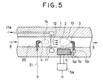
- Fig. 5 shows still another preferred embodiment of the present invention, in which on the inside of a cylindrical body 1 whose cross-section configulation is circular, is formed a tubular passage 2 for transporting powder 8 carried by gas, a desired polarity plasma electrode 3 consisting of a needle electrode having a small radius of curvature at its tip end is disposed on the axis of the tubular passage 2, also an opposite polarity plasma electrode 4 having a large radius of curvature at its tip end is disposed on the same axis as opposed to the desired polarity plasma electrode 3, and between these two plasma electrodes is intermittently applied a D.C. high voltage from a high frequency voltage source 5a through a multi-stage voltage step-up circuit 5 and a discharge gap 5b.
- a desired polarity plasma electrode 3 consisting of a needle electrode having a small radius of curvature at its tip end is disposed on the axis of the tubular passage 2
- an opposite polarity plasma electrode 4 having a large radius of curvature at its tip end
- a ring-shaped dispersing gas jet port 11 is provided at a location a little shifted from the middle of the respective electrodes towards the upstream side.
- a dispersing gas 11a is blown into the tubular passage 2 through this jet port.
- a dispersing gas 11a spout strongly from a dispersing gas jet port 11 just behind this space 14 and making well dispersed powder 12 pass through a space 13 where mainly desired polarity ions exist charging by only the desired polarity ions can be practiced while substantially avoiding neutralization by the opposite polarity ions, and thereby charged powder 9 can be obtained stably for a long period of time.
- positive means for bringing powder remote from the space where the opposite polarity ions exist is provided in other preferred embodiments (Figs. 1, 4, 6 and 8) of the present invention, the embodiment shown in Fig. 5 can be deemed to include means for bringing powder remote from a space where opposite polarity ions exist according to the present invention in certain means, as will be seen from the above description.
- a tubular passage 2 for transporting powder 8 carried by gas along the axis on the upstream side of the inner surface of that tubular passage 2 is disposed on opposite polarity plasma electrode 4 consisting of a needle electrode having a large radius of convature at its tip end, conical means 15 for bringing the powder remote from the electrode 4 is disposed just upstream of the electrode 4, and a desired polarity plasma electrode assembly 3a is disposed as opposed to the conical means 15.
- the desired polarity plasma electrode assembly 3a in this preferred embodiment is composed of two electrodes 3a-1 and 3a-2 disposed close to each other, which are applied with high voltages of different magnitudes from different positions of a D.C. voltage source 5 contained in the cylindrical body 1 through a protective resistor 3a-1R and a discharge gap 5b-1, and a protective resistor 3a-2R and a discharge gap 5b-2, respectively, hence plasma induced by minute spark discharge is formed between the respective electrodes 3a-1 and 3a-2, and thereby a desired magnitude ionic current of sufficient magnitude is drawn intermittently towards the opposite polarity plasma electrode 4, so that a space 13 where mainly desired polarity ions exist can be formed.
- reference numeral 5a designates a high frequency voltage source for supplying electric power to the D.C. voltage source.
- a dispersing gas 11a is fed through these jet ports 11, and after the powder 8 existing within the tubular passage 2 has been well stirred and dispersed by the dispersing gas 11a, the powder comes close to the tube wall and passes through the space 13 where mainly the desired polarity ions exist, and monopolarly charged powder 9 can be obtained.
- a tubular passage 2 for transporting powder 8 carried by gas a desired polarity plasma electrode consisting of a needle electrode having a small radius of curventure at its tip end is disposed on the outlet side of the axis of the tubular passage 2, a high voltage fed from a D.C.
- an adhesion preventing gas 17 is ejected from a desired polarity plasma electrode gas jet port 16 formed around the plasma electrode 3
- an opposite polarity plasma electrode 4 consisting of a needle electrode 4 having a large radius of curvature at its tip end is disposed as opposed to the plasma electrode 3
- around the plasma electrode 4 is disposed a hollow conical body 15 serving as means for bringing powder remote from the opposite polarity plasma electrode 4, and arrangement is done such that an adhesion preventing gas 19 may be blown from the periphery of the opposite polarity plasma electrode 4 through an opposite polarity plasma electrode gas jet port 18.
- the powder would pass through the region around the opposite polarity plasma electrode 4 without entering a space 14 where mainly opposite polarity ions exist, and since thereafter the powder is introduced into a space 13 where mainly desired polarity ion exist while being gathered to the central region of the tubular passage 2 under the condition where the powder has been well dispersed by a dispersing gas 11a ejected from a ring-shaped gas jet port 11, charging of powder can be practiced at a high efficiency, substantially without neutralization of charge caused by the opposite polarity plasma electrode 4, and well charged powder 9 can be obtained.
- a high efficiency can be easily obtained if a voltage-current characteristic of a desired polarity plasma electrode is chosen larger than a voltage-current characteristic of an opposite polarity plasma electrode.
- a voltage-current characteristic of a desired polarity plasma electrode is chosen larger than a voltage-current characteristic of an opposite polarity plasma electrode.
- means for bringing powder remote from a space 14 in which mainly opposite polarity ions exist is provided as in the case with Figs. 1, 3, 4, 5, 6 and 8, in some cases it is not always necessary to make the voltage-current characteristics of the respective plasma electrodes different.
- Fig. 9 shows a still further preferred embodiment of the present invention, in which charging of powder is practiced relying upon a principal effect of the fact that a large difference is maintained between voltage-current characteristics in an operating state of a desired polarity plasma electrode 3 and an opposite polarity plasma electrode 4 according to the present invention.
- Fig. 9 shows a still further preferred embodiment of the present invention, in which charging of powder is practiced relying upon a principal effect of the fact that a large difference is maintained between voltage-current characteristics in an operating state of a desired polarity plasma electrode 3 and an opposite polarity plasma electrode 4 according to the present invention.
- a tubular passage 2 for transporting powder 8 carried by gas a desired polarity plasma electrode 3 having an extremely small radius of curvature at its tip end and having good durability is disposed on the axis of the tubular passage 2, an opposite polarity plasma electrode 4 having a large radius of curvature at its tip end is disposed as opposed to the former plasma electrode 3 and is grounded, also a high voltage is intermittently applied to the desired polarity plasma electrode 3 from a D.C.
- reference numeral 5a designates a high frequency voltage source for feeding electric power to the D.C. high voltage circuit 5.
- the powder carried by gas is already in a well dispersed state and is liable to be charged, and since it passes, at first, through a space 14 where mainly opposite polarity ions exist that is formed downstream of the opposite polarity plasma electrode 4, it is once charged in the opposite polarity, but as it subsequently passes through a space 13 where a strong desired polarity ionic current drawn from the desired polarity plasma electrode 3 having a sufficiently large voltage-current characteristic exists, the previously given charge is offset here, and after the powder has been charged sufficiently in the desired polarity it is ejected as shown by an arrow 9.
- the structure is extremely simple, and depending upon use, the illustrated structure can well achieve the object of the present invention.
- a tubular passage 2 for transporting powder 8 carried by gas on the inner surface of the tubular passage 2 is disposed a desired polarity plasma electrode 3 having an extremely small radius of curveture at its tip end, an opposite polarity plasma electrode 4 having a large radius of curvature at its tip end is disposed as opposed to the former plasma electrode 3, and a D.C. voltage difference is intermittently applied between these plasma electrode from a D.C. voltage source 5 via a discharge gap 5b.
- a dispersing gas jet port 11 for blowing in a dispersing gas 11a in a tangential direction is provided on the inner surface of the tubular passage 2, thereby the gas can be well dispersed under the condition where it has approached to the tube wall, then at first the gas passes through a space 14 where mainly opposite polarity ions exist which space is formed in the proximity of the opposite polarity plasma electrode 4, and thereafter it passes through a space 13 where mainly desired polarity ions exist.
- the space 13 where mainly the desired polarity ions exist is far greater and stronger than the space 14 where mainly the opposite polarity ions exist, and therefore, the powder can be sufficiently charged with the desired polarity as a whole, and is ejected from the apparatus as charged powder 9.
- Fig. 11 shows a still further preferred embodiment of the present invention which is especially suitable for practicing a high-efficiency large-capacity powder charging apparatus in that a plasma generating capability of the desired polarity plasma electrode is chosen especially large.
- a tubular passage 2 for transporting powder 8 carried by gas on the inside of a cylindrical body 1 made of insulating material and having a circular cross-section configuration is formed a tubular passage 2 for transporting powder 8 carried by gas, and on the axis of that tubular passage 2 is disposed an A.C. drive type plasma generating electrode which operates as a desired polarity plasma electrode 3.
- this desired polarity plasma electrode 3 at the center of a thin tubular insulator 3Y made of ceramics or the like is disposed a central electrodes 3Z, on the outside of them is disposed a surface electrode 3X in a head-band shape, between these central electrode 3Z and the surface electrode 3X is applied an A.C. high voltage from an A.C. voltage source 26 via a transformer 27, and furthermore to these electrodes is intermittently applied a D.C. voltage from a D.C. voltage source 5 through a discharge gap 5b.
- An opposite polarity plasma electrode opposed to these electrodes could be normally a corona discharge electrode 4 having a large radius of curvature at its tip end, and if necessary, arrangement is such that an adhesion preventing gas 19 is ejected from an opposite polarity electrode gas jet port 18 provided around the opposite polarity plasma electrode 4 so that adhesion of powder to the tip end of the electrode 4 may be prevented, and this electrode 4 is grounded.
- the apparatus is constructed in such manner that a dispersing gas 11a may be ejected from a ring-shaped dispersing gas jet port 11 opening between the respective electrodes and at this position the carried powder may take a sufficiently dispersed condition.
- the desired polarity plasma electrode used in this embodiment is favorable for realizing an especially strong and large-capacity powder charging apparatus according to the present invention, because extremely strong A.C. plasma is generated in the proximity of the surface electrode 3X by the A.C. high voltage applied between the surface electrode 3X and the central electrode 3Z and thereby the space 13 where mainly the desired polarity ions exist is strongly formed.
- voltage between the respective plasma exciting electrodes 3X and 3Z should not be limited to the system employing a transformer as illustrated in this embodiment, but a ripple voltage superposed on a D.C. voltage could be utilized by appropriately selecting a number of stages and circuit parameters in a high voltage generator circuit.
- Fig. 12 shows a powder charging apparatus according to the present invention which is characterized in that on the inside of a cylindrical body 1 made of insulating material and having a circular cross-section configuration is formed a tubular passage 2 for transporting powder 8 carried by gas, an A.C. plasma generating electrode for intensely generating desired polarity ions is disposed in a ring shape on the inner surface of the tubular passage 2, and an opposite polarity plasma electrode 4 having a large radius of curvature at its tip end is disposed on the axis of the tubular passage 2 as opposed to the A.C. plasma generating electrode.
- an A.C. plasma generating electrode for intensely generating desired polarity ions is disposed in a ring shape on the inner surface of the tubular passage 2
- an opposite polarity plasma electrode 4 having a large radius of curvature at its tip end is disposed on the axis of the tubular passage 2 as opposed to the A.C. plasma generating electrode.
- a thin wire-shaped surface electrode 3X on an inner surface of a ring 3Y normally made of ceramic insulator and provided on the inner surface of the tubular passage 2, is disposed a thin wire-shaped surface electrode 3X, also on the back side of the ring 3Y is disposed a broad planar ring-shaped electrode 3Z, these respective electrodes are supplied with A.C. power by an A.C. voltage 26 so that an A.C. high voltage may be applied between the respective electrodes via a transformer 27, and also a D.C. voltage source 5 for raising the potentials of the respective electrodes applied with the A.C. voltage as a whole is connected to these electrodes through a discharge gap 5b for switching on and off the voltage.
- the opposite polarity plasma electrode 4 is grounded through a lead wire 21, an adhesion preventing gas 19 is adapted to be ejected through an opposite polarity plasma electrode gas jet port 18 around the electrode 4, also a dispersing gas 11a is ejected through a dispersing gas jet port 11 from the middle between the respective electrode and thereby powder can pass through the tubular passage 2 in a well disparsed state as approaching to the inner wall of the tube.
- an adhesion preventing gas 19 is adapted to be ejected through an opposite polarity plasma electrode gas jet port 18 around the electrode 4
- a dispersing gas 11a is ejected through a dispersing gas jet port 11 from the middle between the respective electrode and thereby powder can pass through the tubular passage 2 in a well disparsed state as approaching to the inner wall of the tube.
- a desired polarity plasma electrode mainly a corona discharge electrode having a small radius of curvature or an A.C. plasma generating electrode is employed, as an opposite polarity plasma electrode a corona discharge electrode consisting of a needle electrode having a relatively large radius of curvature is employed, and besides, as means for dispersing powder some embodiments employ a choke, some employ a dispersing gas and some employ a turning flow, or else a dispersing plate consisting of a baffe plate could be employed.
- some embodiments employ a space where the gas carrying the powder is not flowing, some employ a conical body, or else a diameter of a tubular passage is varied along the lengthwise direction of the tube, or as shown in Fig. 6 a baffle device is employed.
- a baffle device is employed.
- a system in which gas is ejected so as to surround the electrodes a system employing an A.C.-driven plasma generating electrode as shown in Figs. 11 and 12 as an electrode, or a system consisting of a combination of the above-mentioned systems, could be utilized as selected according to necessity.
- Fig. 13 shows one preferred embodiment in which an electrostatic powder painting apparatus having extremely excellent penetrating performance is formed by making use of the above-descried powder charging apparatus according to the present invention.
- a desired polarity plasma electrode 3 consisting of a needle electrode having a small radius of curvature at its tip end is disposed in the proximity of a terminal end of the tubular passage 2
- an opposite polarity plasma electrode 4 consisting of a needle-like corona discharge electrode having a large radius of curvature at its tip end is disposed as opposed to the former plasma electrode 3, a high voltage is applied intermittently to the opposite polarity plasma electrode 4 from a D.C.
- Reference numeral 5a designates a high frequency voltage source for feeding electric power to the D.C. voltage source.
- a choke 10 At the upstream of the opposite polarity plasma electrode 4 is disposed, for example, a choke 10, if necessary, for the purpose of well dispersing the powder, thereby the powder passes at first through a space where mainly opposite polarity ions exist in a well dispersed state, thereafter it passes a space where mainly desired polarity ions exist, and it is ejected from the end of the tubular passage 2 as charged powder 9.
- a dispersing plate 28 is disposed, thereby appropriate divergence is given to the ejecting pattern, and in the case where the divergence caused by the dispersing plate is made small, provision is made such that a pattern adjusting gas indicated by an arrow 30 may be ejected from a pattern adjusting gas jet port 29 to adjust the pattern.
- reference numeral 31 designates an article to be painted.
- the lead wire 20 is connected to a terminal having an appropriate magnitude of D.C. potential in the voltage source 5 to form a weak electric field and thereby an electrostatic powder painting apparatus having an appropriate and high efficiency and an excellent penetrating performance is provided.
- Such embodiments are also included in the scope of the present invention.
- adhesion preventing gases 17 and 19 are used.
- Fig. 14 shows another embodiment for providing an electrostatic powder painting apparatus that is very favorable in the case of practicing a thick-film electrostatic powder painting apparatus by making use of the powder charging apparatus according to the present invention.
- a tubular passage 2 for transporting powder 8 carried by gas on the inside of a cylindrical body 1 made of insulating material and having a circular cross-section configuration is formed a tubular passage 2 for transporting powder 8 carried by gas, a short tube 22 including an adjusting device 29 for adjusting a powder ejecting pattern is provided on the outlet side of the tubular passage 2 along its axis, a desired polarity plasma electrode 3 consisting of a corona discharge electrode having an extremely small radius of curvature at its tip end is disposed at the upstream of the short tube 22, an opposite polarity plasma electrode 4 having a relatively large radius of curvature at its tip end is disposed as opposed to the former plasma electrode 3 and is grounded, and a D.C.
- discharge gap 5b is shown as located in the both end portions of a lead wire 5c in the drawings, this indicates merely possible mount positions of the discharge gap 5b, and it suffices to provide only in either one end portion.
- reference numeral 5a designates a high frequency voltage source for feeding electric power to the D.C. high voltage source 5.
- reference numeral 31 designates an article to be painted
- reference numeral 16 designates a jet port for ejecting an adhesion preventing gas 17 which serves to prevent the powder from adhering to the tip end of the desired polarity plasma electrode.
- well dispersed powder can be sufficiently charged between the desired polarity plasma electrode and the opposite polarity plasma electrode, and it passes through the short tube 22 and is blown to the article to be painted.
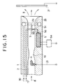
- Fig. 15 shows still another embodiment for providing a very high performance electrostatic powder painting apparatus having a very high painting efficiency and an excellent back painting property by making use of the powder charging apparatus according to the present invention.
- a desired polarity plasma electrode 3 is disposed on the axis of the tubular passage 2 on its outlet side, a high voltage is applied intermittently to this plasma electrode 3 by means of a voltage source 5 and a discharge gap 5b, and also there is provided an anti-object corona electrode 23 connected to the plasma electrode 3 and directed to the outlet side.
- a corona discharge electrode having a relatively large radius of curvature at its tip end is disposed as shown in Fig. 15, and this plasma electrode 4 is grounded via a lead wire 21.
- reference numeral 5a designates a high frequency voltage source for feeding electric power to the D.C. voltage source 5.
- an adhesion preventing gas indicated by an arrow 17 is used for the purpose of preventing the powder from adhering to the tip end of the desired polarity plasma electrode and the tip end of the anti-object corona electrode 23.
- a pattern adjusting gas indicated by an arrow 30 is ejected in a turning flow from a pattern adjusting gas jet port 29 opening in the proximity of an end of the tubular passage 2 so that an ejecting pattern of the charged powder 9 blown from the electrostatic powder painting apparatus can be adjusted by regulating the flow rate of this gas.
- powder charged very strongly in the same polarity as the desired polarity plasma electrode in the region between the desired polarity plasma electrode 3 and the opposite polarity plasma electrode 4 is ejected, and furthermore, in addition thereto since the powder is again charged by an intense electric field and a corona discharge current established from the tip end of the anti-object corona electrode 23 towards the object, i.e. the article to be painted, the powder can practice electrostatic powder painting with extremely high painting efficiency and back painting property, owing to a strong electric field directed from the tip end of the electrostatic powder painting apparatus towards the article to be painted as well as a large amount of charge on the powder.
- the means for practicing the basic elements of the powder charging apparatus according to the present invention as described in detail above can be arbitrarily selected and combined depending upon the purpose, and also with regard to the methods for forming and adjusting the ejecting pattern, besides the illustrated means, every means known in the art can be employed. This is also true with respect to the embodiments shown in Figs. 13 and 14, respectively.
- Fig. 16 shows yet another embodiment, in which an electrostatic powder painting apparatus having well matched penetrating performance and painting efficiency can be provided by making use of the powder charging apparatus according to the present invention.
- a tubular passage for transporting powder 8 carried by gas on the inside of a cylindrical body 1 made of insulating material and having a circular cross-section area, is formed a tubular passage for transporting powder 8 carried by gas, an anti-object corona electrode 23 opposed to an article 31 to be painted is provided on the axis of the tubular passage 2 on the outlet side thereof, a desired polarity plasma electrode 3 is disposed at the upstream of the corona electrode 23 a little apart therefrom, an output terminal 5d at the highest voltage of a D.C.
- an electrostatic powder painting apparatus having both a penetrating performance and a painting efficiency which are intermediate and well matched with each other, can be provided.
- the present invention has the above-described features, and since the pair of electrodes used for charging powder are both plasma generating electrodes such as needle electrodes, knife-edge electrodes, wire electrodes, A.C. drive type electrodes, etc., stable operation in powder for a long period of time can be assumed without adhesion and accumulation of powder to and on the respective electrodes, and for the purpose of charging of powder paint, strong long-time stable charging performance can be assured almost independently of material properties of the powder. Especially, according to the present invention, since a D.C. voltage is applied intermittently between the respective electrodes, as compared to the case where the same D.C. voltage is applied continuously, an amount of charge can be increased by 30 - 100 %.
- an electrostatic powder painting apparatus having extremely excellent penetrating performance, thick painting performance, painting efficiency and back painting performance, can be newly provided, and all these apparatuses present high performance stability in a long term operation.
- the external electrical field and the external ionic current employed in the above-described electrostatic powder painting apparatus is very inportant even in the case where the external electric field and the external ionic current are not present at all, and it was considered almost impossible in the prior art to practice such electrostatic powder painting stably and at a high efficiency for a long term independently of material properties of powder paint.
- one of a pair of electrodes employed for charging powder is a corona discharge electrode 43, while the other is a cylindrical electrode 44 which can be deemed substantially to be a plane, and under an operating conditions, since there exist only a high voltage applied between the respective electrodes and a monopolar desired polarity ionic current flowing unidirectionally, essentially powder is apt to adhere to and accumulate on the surface of the cylindrical electrode 44, and even a little powder, once it has adhered to the electrode 44, it causes generation of back corona discharge, an opposite polarity ionic current flows inversely from this electrode 44 towards the corona discharge electrode 43, resulting in neutralization of the desired polarity ions and electric charge, thereby charging performance of the electrodes would be lowered quickly as the powder adheres and accumulates, and continuous operation for a long term would become difficult.
- This phenomenon is especially remarkable in the case of charging powder having a low melting point and strong adhesiveness, and it is practically impossible to realize practical stable operation for more than several hours even with counter-measures such as improvements in the material, shape and surface working of the cylindrical electrode 49 and in the flow rate and ejecting velocity of a clean air 58.
Landscapes
- Electrostatic Spraying Apparatus (AREA)
- Physical Or Chemical Processes And Apparatus (AREA)
Description
- This invention relates to powder charging for example for electrostatic powder painting.
- It is known from DE-A-2646798 to provide an insulative tubular passage with a pair of needle electrodes connected to high potential sources of opposite polarity and thus create a field therebetween through which the powder flows carried by a conveying gas.
- Further prior art is shown in Figures 17 and 18 of the drawings accompanying this specification, in which the field is generated between the corona
discharge needle electrode 43 and thecylindrical electrode 44. Additional gas is blown into the passage with the object of reducing or minimising powder build-up on the electrodes. - The problems with the prior art are that powder may be caused to adhere to one of the electrodes even despite the cleaning gas, and this causes generation of back corona discharge, an opposite polarity ionic current and effectively neutralization of the desired charging of the power particles. Further problems are due to gravitational effects on the powder which tend to cause it to flow non-uniformly in relation to the cross section of the passage, and the non-uniformity of the current density in relation thereto.
- The object of the invention is to solve these problems and provide improvements.
- According to the invention there is provided a powder charging apparatus which comprises an insulative tubular passage, means for delivering to the tubular passage a conveying gas and the powder to be charged, a pair of plasma electrodes for respectively generating plasma of required polarity and plasma of opposite polarity, means for applying DC voltage to said plasma electrodes, said plasma electrodes being connected so that the field therebetween extends in said tubular passage and the apparatus being arranged so that the said powder flows in a dispersed state in said gas through an area of said field where mainly ions of required polarity exist. one of said pair of plasma electrodes being a plasma electrode of required polarity and the other being a plasma electrode of opposite polarity, and is characterised in that the location of the other of the electrodes relative to the powder flow is such that it is substantially avoided that the powder in the dispersed state flows through the area of the field where mainly ions of said opposite polarity exist, and said DC voltage is intermittently applied via a gap which disperses ions well in said insulative tubular passage
Also according to the invention there is provided an electrostatic powder painting apparatus which comprises a powder charging apparatus including an insulative tubular passage, means for delivering to the tubular passage a conveying gas and the powder to be charged, a pair of plasma electrodes for respectively generating plasma of required polarity and plasma of opposite polarity, means for applying DC voltage to said plasma electrodes, said plasma electrodes being connected so that the field therebetween extends in said tubular passage and the apparatus being arranged so that the said powder flows in a dispersed state in said gas through an area of said field where mainly ions of required polarity exist, one of said plasma electrodes being a plasma electrode of required polarity and the other being a plasma electrode of opposite polarity, and is characterised in that the location of said other electrode relative to the powder flow is such that it is substantially avoided that the powder in the dispersed state flows through the area of the field where mainly ions of said opposite polarity exist, and said DC voltage is intermittently applied via a gap which disperses ions well in said insulative tubular passage
The invention also provides a powder charging method including the steps of providing an insulative tubular passage, with one plasma electrode on an axis there in for generating plasma of required polarity and another plasma electrode therein for generating plasma of opposite polarity, delivering a conveying gas and powder to be charged to the passage, applying D.C. voltage to said electrodes to create a field therebetween extending in said tubular passage so that the powder flows in dispersed state through an area of said field where mainly ions of required polarity exist, and characterised in that the location of said other electrode relative to the powder flow is such that it is substantially avoided that the powder in the dispersed state flows through the area of the field where mainly ions of said opposite polarity exist, and in that said D C. voltage is applied intermittently between said electrodes to generate plasma in said passage in the direction of said axis and the powder is transported in said passage in the direction of said axis
Finally the invention provides a powder charging method including the steps of delivering a conveying gas and the powder to a tubular insulative passage with a pair of plasma generating electrodes therein, for respectively generating plasma of required polarity and plasma of opposite polarity and applying D.C voltage intermittently to said plasma electrodes which are so connected that the field therebetween extends in said tubular passage and so that the powder flows in said gas through an area of the field where mainly ions of required polarity exist and characterised in that the location of the electrode for generating plasma of opposite polarity relative to the powder flow is such that it is substantially avoided that the powder in the dispersed state flows through the area of the field where mainly ions of said opposite polarity exist, and in that said powder is caused to flow only through the area where the mainly desired polarity ions exist -
- Fig. 1 is a longitudinal cross-section view of a powder charging apparatus according to the present invention;
- Fig. 2 is a cross-section view token along line II-II in Fig. 1 as viewed in the direction of arrows;
- Figs. 3, 4, 5 and 6, respectively, are longitudinal cross-section views of other preferred embodiments of the present invention;
- Fig. 7 is a cross-section view taken along line VII-VII in Fig. 6 as viewed in the direction of arrows;
- Figs. 8, 9, 10, 11 and 12, respectively, are longitudinal cross-section views of still other preferred embodiments of the present invention;
- Figs. 13, 14, 15 and 16, respectively, are longitudinal cross-section views of different preferred embodiments of an electrostatic powder painting apparatus according to the present invention; and
- Figs. 17 and 18, respectively, are longitudinal cross-section views of two different examples of the powder charging apparatuses in the prior art.
- In the preferred embodiment of the present invention illustrated in Figs. 1 and 2, a desired
polarity plasma electrode 3 is a needle electrode having a small radius of curvature at its tip end and forms a low voltage side plasma electrode, whereas an oppositepolarity plasma electrode 4 is a needle electrode having a large radius of curvature at its tip end and forms a high voltage side plasma electrode, and between these two electrodes is intermittently applied a high voltage of 20,000 - 80,000 volts from aD.C. voltage source 5 through adischarge gap 5b. As a result, between the respective electrodes is intermittently generated bipolar corona discharge as shown in Fig. 1, and at the tip ends of the respective electrodes is respectively formed plasma. In this instance, since the radius of curvature at the tip end of the desiredpolarity plasma electrode 3 is small, a desired polarityionic current 6 drawn from this electrode is large as compared to an opposite polarityionic current 7 drawn from the oppositepolarity plasma electrode 4, and also is present over a long broad region. Accordingly, powder carried by gas indicated by anarrow 8 is stirred by achoke 10 and a dispersinggas 11a ejected from a dispersinggas jet 11 provided at this choce and becomes well dispersedpowder 12, and then it is charged while passing through aspace 13 where mainly desired polarity ions exist and becomes chargedpowder 9. - In this case, as will be apparent from Fig. 1, since a
space 14 where mainly opposite polarity ions exist is substantially separated from thetubular passage 2 bymeans 14 for bringing the powder remote from this space, it scarcely occurs that the electric charge produced by the desired polarity ionic current is neutralized by the opposite polarityionic current 7, and furthermore, this is further assured by anadhesion preventing gas 19 fed through an opposite polarity plasma electrodegas jet port 18 around the opposite polarity plasma electrode. In the powder charging apparatus according to the present invention, since the used electrodes are both corona discharge electrodes having plasma formed at their tip ends, owing to the effects of ionic currents, electric winds, D.C. repulsions, etc. issued from the electrodes by the actions of the plasmas and the electric fields generated at the tip ends of the respective corona discharge electrodes, the plasma electrodes have the effects of charging the particles existing in the proximity of the electrode and ejecting them, so that powder particles would not adhere to and accumulate on the electrodes during operation, performances of the electrodes would not change and operation can be continued stably for a long period of time. It is to be noted that around the desiredpolarity plasma electrode 3 is also provided a desired polarity plasma electrodegas jet port 16 in a ring shape, and through thisgas jet 16 anadhesion preventing gas 17 is blown in at a high velocity. Theadhesion preventing gases - Since an
output terminal 5a of theD.C. voltage source 5 and the oppositepolarity plasma electrode 4 are connected via adischarge gap 5b, theopposite polarity electrode 4 is fed with a voltage from theD.C. voltage source 5 via thedischarge gap 5b, and while the voltage is increasing as the feeding time elapses, when the voltage has become a high voltage, between thatelectrode 4 and the desiredpolarity plasma electrode 3 are momentarily generated the opposite polarityionic current 7 and the desire polarityionic current 6, hence the voltage of the oppositepolarity plasma electrode 4 is lowered abruptly, and the above-mentioned respectiveionic currents - If the currents cease, the voltage of the opposite
polarity plasma electrode 4 is again raised by the voltage of theD.C. voltage source 5 fed through thedischarge gap 5b, and the above-described operation is repeated. The repetition is effected normally at a frequency of 5KC - 50KC. - In this way, the respective
ionic currents - It is to be noted that if a powder charging apparatus according to the present invention of the type shown in Fig. 1 and having a large capacity is necessitated, the object can be achieved by providing the electrode pair in multiple along the direction of flow in the tubular passage.
- In another preferred embodiment shown in Fig. 3, on the inside of a
cylindrical body 1 made of insulating material whose cross-section configuration is circular, is formed atubular passage 2 for transportingpowder 8 carried by gas, on the axis of thistubular passage 2 is disposed a thin corona discharge electrode so as to operate as a desiredpolarity plasma electrode 3, and a thick corona discharge electode opposed to thatplasma electrode 3 is provided on an outer peripheral surface of thetubular passage 2 so as to operate as an oppositepolarity plasma electrode 4. In this instance, the inner surface of thetubular passage 2 where the oppositepolarity plasma electrode 4 is disposed form a surface converging towards the upstream which is contiguous to achoke 10 at the upstream, also at the downstream of that inner surface, a dispersing gas indicated by anarrow 11a is ejected from a ring-shaped dispersinggas jet port 11 to keep the tip end of the oppositepolarity plasma electrode 4 always clean, hence well dispersedpowder 12 is produced by the effect that the dispersing gas traverses thetubular passage 2 to stir and disperse the powder and is blown towards aspace 13 where mainly a desired polarityionic current 6 drawn from the tip end of the desiredpolarity plasma electrode 3 exists, and thereby the powder can be charged. In this case, since the opposite polarityionic current 7 drawn from the oppositepolarity plasma electrode 4 is in itself small because of the large radius of curvature at the tip end of theelectrode 4 and the construction is such that the powder may be brought remote from thespace 7 where mainly the opposite polarity ions exist due to thechoce 10, neutralization of the charge of the desired polarity by the opposite polarity ions can be suppressed small, and after all, a charging efficiency can be made high as a whole. In this embodiment,reference numeral 5 designates a D.C. voltage source for applying D.C. voltages to the respective electrodes, one end of alead wire 5c is connected to anoutput terminal 5d of theD.C. voltage source 5, and the other end thereof is opposed to the desiredpolarity plasma electrode 3 via adischarge gap 5b of 1 - 5 mm.Reference numeral 5a designates a high frequency voltage source for supplying electric power to that electrode. It is to be noted that the desiredpolarity plasma electrode 3 operates as a high voltage side plasma electrode and is disposed within aprotective tube 3a, and anadhesion preventing gas 17 ejected at a high velocity from a high voltage side plasma electrodegas jet port 16a at the tip end of theprotective tube 3a, serves to prevent discharge products produced in thedischarge gap 5b and the powder from adhering to the tip end of the desired polarityplasma discharge electrode 3, which would occur mainly under a transient condition upon starting or stopping. - Fig. 4 shows another preferred embodiment, in which a desired
polarity plasma electrode 3 is provided on an inner surface of atubular passage 2 formed by acylindrical body 1. In this embodiment,powder 8 carried by gas is introduced from a tangential direction of thetubular passage 2 to the upstream side of the desiredpolarity plasma electrode 3 by means of a powder introducingtubular passage 1a, and anadhesion preventing gas 19 is supplied through an opposite polarity plasma electrodegas jet port 18 formed around an oppositepolarity plasma electrode 4. Thus, by a D.C. high voltage applied intermittently between the grounded oppositepolarity plasma electrode 4 and the desiredpolarity plasma electrode 3 from avoltage source 5 via adischarge gap 5b, corona discharge is generated intermittently between the respective electodes, and as shown in Fig. 3, a desired polarityionic current 6 drawn from the desiredpolarity plasma electrode 3 forms aspace 13 along the tube wall where mainly desired polarity ions exist. In this case, the powder introduced into thetubular passage 2 through a powder introducingside port 24 would turn round at a high velocity in thetubular passage 2 and would become well dispersedpowder 12 along the tube wall, then it flows out as traversing thespace 13 where mainly the desired polarity ions exist, and therefore, well chargedpowder 9 can be obtained. In this case, since thepowder 8 would not enter thespace 14 where mainly an opposite polarityionic current 7 exists as assisted by the action of theadhesion preventing gas 19, neutralization by the opposite polarityionic current 7 of the charge given by the desired polarityionic current 6 can be suppressed to a very small amount. In this embodiment, while an adhesion preventing gas could be blown towards the desiredpolarity plasma electrode 3 if necessary, in many cases the powder can be prevented from adhering to the desiredpolarity plasma electrode 3 by a strong turning flow itself with the illustrated construction. - Fig. 5 shows still another preferred embodiment of the present invention, in which on the inside of a
cylindrical body 1 whose cross-section configulation is circular, is formed atubular passage 2 for transportingpowder 8 carried by gas, a desiredpolarity plasma electrode 3 consisting of a needle electrode having a small radius of curvature at its tip end is disposed on the axis of thetubular passage 2, also an oppositepolarity plasma electrode 4 having a large radius of curvature at its tip end is disposed on the same axis as opposed to the desiredpolarity plasma electrode 3, and between these two plasma electrodes is intermittently applied a D.C. high voltage from a highfrequency voltage source 5a through a multi-stage voltage step-upcircuit 5 and adischarge gap 5b. In addition, at a location a little shifted from the middle of the respective electrodes towards the upstream side is provided a ring-shaped dispersinggas jet port 11, and a dispersinggas 11a is blown into thetubular passage 2 through this jet port. Normally, in a powder charging apparatus of the class required for electrostatic powder painting or the like, in many cases transportion of powder through a tubular passage is not effected at so high velocity, and in such cases the powder carried by gas form a deviated flow as shown at 25, hence even if the powder flow should pass through aspace 14 where mainly opposite polarity ions exist which space is formed in the proximity of the tip end of the oppositepolarity plasma electrode 4, in most cases the powder would not be charged so much in substance. Accordingly, by making a dispersinggas 11a spout strongly from a dispersinggas jet port 11 just behind thisspace 14 and making well dispersedpowder 12 pass through aspace 13 where mainly desired polarity ions exist, charging by only the desired polarity ions can be practiced while substantially avoiding neutralization by the opposite polarity ions, and thereby chargedpowder 9 can be obtained stably for a long period of time. Although positive means for bringing powder remote from the space where the opposite polarity ions exist is provided in other preferred embodiments (Figs. 1, 4, 6 and 8) of the present invention, the embodiment shown in Fig. 5 can be deemed to include means for bringing powder remote from a space where opposite polarity ions exist according to the present invention in certain means, as will be seen from the above description. - In yet another preferred embodiment of the present invention shown in Figs. 6 and 7, on the inside of a
cylindrical body 1 having a circular cross-section configuration and made of insulating material is formed atubular passage 2 for transportingpowder 8 carried by gas, along the axis on the upstream side of the inner surface of thattubular passage 2 is disposed on oppositepolarity plasma electrode 4 consisting of a needle electrode having a large radius of convature at its tip end,conical means 15 for bringing the powder remote from theelectrode 4 is disposed just upstream of theelectrode 4, and a desired polarityplasma electrode assembly 3a is disposed as opposed to theconical means 15. The desired polarityplasma electrode assembly 3a in this preferred embodiment is composed of twoelectrodes 3a-1 and 3a-2 disposed close to each other, which are applied with high voltages of different magnitudes from different positions of aD.C. voltage source 5 contained in thecylindrical body 1 through aprotective resistor 3a-1R and adischarge gap 5b-1, and aprotective resistor 3a-2R and adischarge gap 5b-2, respectively, hence plasma induced by minute spark discharge is formed between therespective electrodes 3a-1 and 3a-2, and thereby a desired magnitude ionic current of sufficient magnitude is drawn intermittently towards the oppositepolarity plasma electrode 4, so that aspace 13 where mainly desired polarity ions exist can be formed. It is to be noted thatreference numeral 5a designates a high frequency voltage source for supplying electric power to the D.C. voltage source. In the middle between these desired polarity plasma electrode and opposite polarity plasma electrode are formed a plurality of turningflow jet ports 11 opening in thetubular passage 2, a dispersinggas 11a is fed through thesejet ports 11, and after thepowder 8 existing within thetubular passage 2 has been well stirred and dispersed by the dispersinggas 11a, the powder comes close to the tube wall and passes through thespace 13 where mainly the desired polarity ions exist, and monopolarlycharged powder 9 can be obtained. In this embodiment, owing to the actions of both themeans 15 for bringing thepowder 8 remote from the oppositepolarity plasma electrode 4 and the turningflow jet port 11 which serves as a dispersing gas jet port, the powder would scarcely come close to aspace 14 where mainly opposite polarity ions exist, so that neutralization of charge caused by the opposite polarity ions can be substantially avoided, and thereby stable charging of powder can be practiced at a high efficiency for a long period of time. It is to be noted that either one of the above-describeddischarge gaps 5b-1 and 5b-2 can be omitted without any inconvenience. - In a further preferred embodiment shown in Fig. 8, on the inside of a
cylindrical body 1 made of insulating material and having a circular cross-section configuration is formed atubular passage 2 for transportingpowder 8 carried by gas, a desired polarity plasma electrode consisting of a needle electrode having a small radius of curventure at its tip end is disposed on the outlet side of the axis of thetubular passage 2, a high voltage fed from aD.C. voltage source 5 is intermittently applied to thisplasma electrode 3 through adischarge gap 5b, anadhesion preventing gas 17 is ejected from a desired polarity plasma electrodegas jet port 16 formed around theplasma electrode 3, an oppositepolarity plasma electrode 4 consisting of aneedle electrode 4 having a large radius of curvature at its tip end is disposed as opposed to theplasma electrode 3, around theplasma electrode 4 is disposed a hollowconical body 15 serving as means for bringing powder remote from the oppositepolarity plasma electrode 4, and arrangement is done such that anadhesion preventing gas 19 may be blown from the periphery of the oppositepolarity plasma electrode 4 through an opposite polarity plasma electrodegas jet port 18. - In this preferred embodiment, since the powder would pass through the region around the opposite
polarity plasma electrode 4 without entering aspace 14 where mainly opposite polarity ions exist, and since thereafter the powder is introduced into aspace 13 where mainly desired polarity ion exist while being gathered to the central region of thetubular passage 2 under the condition where the powder has been well dispersed by a dispersinggas 11a ejected from a ring-shapedgas jet port 11, charging of powder can be practiced at a high efficiency, substantially without neutralization of charge caused by the oppositepolarity plasma electrode 4, and wellcharged powder 9 can be obtained. - In the powder charging apparatus according to the present invention, generally a high efficiency can be easily obtained if a voltage-current characteristic of a desired polarity plasma electrode is chosen larger than a voltage-current characteristic of an opposite polarity plasma electrode. However, in the case where means for bringing powder remote from a
space 14, in which mainly opposite polarity ions exist, is provided as in the case with Figs. 1, 3, 4, 5, 6 and 8, in some cases it is not always necessary to make the voltage-current characteristics of the respective plasma electrodes different. - Fig. 9 shows a still further preferred embodiment of the present invention, in which charging of powder is practiced relying upon a principal effect of the fact that a large difference is maintained between voltage-current characteristics in an operating state of a desired
polarity plasma electrode 3 and an oppositepolarity plasma electrode 4 according to the present invention. In Fig. 9, on the inside of acylindrical body 1 made of insulating material and having a circular cross-section configuration is formed atubular passage 2 for transportingpowder 8 carried by gas, a desiredpolarity plasma electrode 3 having an extremely small radius of curvature at its tip end and having good durability is disposed on the axis of thetubular passage 2, an oppositepolarity plasma electrode 4 having a large radius of curvature at its tip end is disposed as opposed to theformer plasma electrode 3 and is grounded, also a high voltage is intermittently applied to the desiredpolarity plasma electrode 3 from aD.C. voltage source 5 via adischarge gap 5b, further a dispersinggas 11a is ejected from a ring-shaped dispersinggas jet port 11 provided in the region of achoke 10 formed at the upstream of the oppositepolarity plasma electrode 4 to feed the powder to the plasma electrodes in a well dispersed condition, and then the powder is made to pass through the desired polarity plasma electrode region, it is to be noted thatreference numeral 5a designates a high frequency voltage source for feeding electric power to the D.C.high voltage circuit 5. With the above-mentioned provision, the powder carried by gas is already in a well dispersed state and is liable to be charged, and since it passes, at first, through aspace 14 where mainly opposite polarity ions exist that is formed downstream of the oppositepolarity plasma electrode 4, it is once charged in the opposite polarity, but as it subsequently passes through aspace 13 where a strong desired polarity ionic current drawn from the desiredpolarity plasma electrode 3 having a sufficiently large voltage-current characteristic exists, the previously given charge is offset here, and after the powder has been charged sufficiently in the desired polarity it is ejected as shown by anarrow 9. In order to achieve such object, it is neccessary to give a large difference between the charging characteristics of the respective electrodes, and although in some cases selection of a flow rate and polarity of the powder to be processed may be limited, the structure is extremely simple, and depending upon use, the illustrated structure can well achieve the object of the present invention. - It is to be noted that even if the means 10, 11 for dispersing gas as employed in the above-described embodiment is not especially provided, in the event that powder can be supplied to the region where the electrodes exist already in a well dispersed state depending upon characteristics, a feed rate and a flow velocity of the carrier gas, in some cases these powder dispersing means are unnecessary to be especially provided. The embodiment in such cases is also included in the scope of the present invention.
- In a yet further preferred embodiment shown in Fig. 10, on the inside of a
cylindrical body 1 having a circular cross-section configuration is formed atubular passage 2 for transportingpowder 8 carried by gas, on the inner surface of thetubular passage 2 is disposed a desiredpolarity plasma electrode 3 having an extremely small radius of curveture at its tip end, an oppositepolarity plasma electrode 4 having a large radius of curvature at its tip end is disposed as opposed to theformer plasma electrode 3, and a D.C. voltage difference is intermittently applied between these plasma electrode from aD.C. voltage source 5 via adischarge gap 5b. In this case, like the other embodiments it is not always necessary to ground one of the electrodes, but the case where a potential difference is maintained between the respective electrodes while applying two different voltages from ungrounded terminals of thevoltage source 5 to the respective electrodes just as this embodiment, is also included in the scope of the present invention. - In addition, in this preferred embodiment, a dispersing
gas jet port 11 for blowing in a dispersinggas 11a in a tangential direction is provided on the inner surface of thetubular passage 2, thereby the gas can be well dispersed under the condition where it has approached to the tube wall, then at first the gas passes through aspace 14 where mainly opposite polarity ions exist which space is formed in the proximity of the oppositepolarity plasma electrode 4, and thereafter it passes through aspace 13 where mainly desired polarity ions exist. However, in this instance there is a large difference in the radius of curvature at the tip end of the corona electrode, hence thespace 13 where mainly the desired polarity ions exist is far greater and stronger than thespace 14 where mainly the opposite polarity ions exist, and therefore, the powder can be sufficiently charged with the desired polarity as a whole, and is ejected from the apparatus as chargedpowder 9. - In this embodiment also, like the embodiment shown in Fig. 9, in the event that the powder comes into the
tubular passage 2 in a already well dispersed state, in some case the dispersing means 11 and the dispersinggas 11a for the powder are not always necessary, but such case is also included in the scope of the present invention. - Fig. 11 shows a still further preferred embodiment of the present invention which is especially suitable for practicing a high-efficiency large-capacity powder charging apparatus in that a plasma generating capability of the desired polarity plasma electrode is chosen especially large.
- In Fig. 11, on the inside of a
cylindrical body 1 made of insulating material and having a circular cross-section configuration is formed atubular passage 2 for transportingpowder 8 carried by gas, and on the axis of thattubular passage 2 is disposed an A.C. drive type plasma generating electrode which operates as a desiredpolarity plasma electrode 3. In this desiredpolarity plasma electrode 3, at the center of a thintubular insulator 3Y made of ceramics or the like is disposed acentral electrodes 3Z, on the outside of them is disposed asurface electrode 3X in a head-band shape, between thesecentral electrode 3Z and thesurface electrode 3X is applied an A.C. high voltage from anA.C. voltage source 26 via atransformer 27, and furthermore to these electrodes is intermittently applied a D.C. voltage from aD.C. voltage source 5 through adischarge gap 5b. - An opposite polarity plasma electrode opposed to these electrodes could be normally a
corona discharge electrode 4 having a large radius of curvature at its tip end, and if necessary, arrangement is such that anadhesion preventing gas 19 is ejected from an opposite polarity electrodegas jet port 18 provided around the oppositepolarity plasma electrode 4 so that adhesion of powder to the tip end of theelectrode 4 may be prevented, and thiselectrode 4 is grounded. - In addition, the apparatus is constructed in such manner that a dispersing
gas 11a may be ejected from a ring-shaped dispersinggas jet port 11 opening between the respective electrodes and at this position the carried powder may take a sufficiently dispersed condition. The desired polarity plasma electrode used in this embodiment is favorable for realizing an especially strong and large-capacity powder charging apparatus according to the present invention, because extremely strong A.C. plasma is generated in the proximity of thesurface electrode 3X by the A.C. high voltage applied between thesurface electrode 3X and thecentral electrode 3Z and thereby thespace 13 where mainly the desired polarity ions exist is strongly formed. - It is to be noted that in the case of the above-described desired
polarity plasma electrode 3, since powder particles cannot approach to the proximity of thisplasma electrode 3 due to an action of an extremely strong and uneven A.C. electric field formed in the proximity of thesurface electrode 3X, in many cases there is no need to employ special adhesion preventing means, but for the purpose of preventing adhesion of powder upon starting and stopping an adhesion preventing gas could be introduced to the proximity of this electrode. In this figure, reference numerals not specifically referred to, are given to items which are common to other figures. In addition, the means for applying an A.C. voltage between the respective plasmaexciting electrodes - Fig. 12 shows a powder charging apparatus according to the present invention which is characterized in that on the inside of a
cylindrical body 1 made of insulating material and having a circular cross-section configuration is formed atubular passage 2 for transportingpowder 8 carried by gas, an A.C. plasma generating electrode for intensely generating desired polarity ions is disposed in a ring shape on the inner surface of thetubular passage 2, and an oppositepolarity plasma electrode 4 having a large radius of curvature at its tip end is disposed on the axis of thetubular passage 2 as opposed to the A.C. plasma generating electrode. In Fig. 12, on an inner surface of aring 3Y normally made of ceramic insulator and provided on the inner surface of thetubular passage 2, is disposed a thin wire-shapedsurface electrode 3X, also on the back side of thering 3Y is disposed a broad planar ring-shapedelectrode 3Z, these respective electrodes are supplied with A.C. power by anA.C. voltage 26 so that an A.C. high voltage may be applied between the respective electrodes via atransformer 27, and also aD.C. voltage source 5 for raising the potentials of the respective electrodes applied with the A.C. voltage as a whole is connected to these electrodes through adischarge gap 5b for switching on and off the voltage. In addition, the oppositepolarity plasma electrode 4 is grounded through alead wire 21, anadhesion preventing gas 19 is adapted to be ejected through an opposite polarity plasma electrodegas jet port 18 around theelectrode 4, also a dispersinggas 11a is ejected through a dispersinggas jet port 11 from the middle between the respective electrode and thereby powder can pass through thetubular passage 2 in a well disparsed state as approaching to the inner wall of the tube. In this embodiment, since extremely intense A.C. plasma is formed in the periphery of theelectrode 3X by the action of the high A.C. voltage applied between theelectrode 3X and theelectrode 3Z, an extremely large amount of desired polarity ions would flow without interruption towards the opposite polarity plasma electrode owing to an D.C. electric field established from theseelectrodes polarity plasma electrode 4 by theD.C. voltage source 5. Accordingly, the powder passing through the proximity of these electrodes as well dispersed and close to the tube wall can be ejected as very strongly chargedpowder 9, according to this system a preferred embodiment of the present invention which is extremely suitable in the event that it is desired to obtain powder having a high charge density in a large amount, can be established. - In the preferred embodiments of the present invention illustrated in Figs. 1 to 12 and described in detail above, as a desired polarity plasma electrode mainly a corona discharge electrode having a small radius of curvature or an A.C. plasma generating electrode is employed, as an opposite polarity plasma electrode a corona discharge electrode consisting of a needle electrode having a relatively large radius of curvature is employed, and besides, as means for dispersing powder some embodiments employ a choke, some employ a dispersing gas and some employ a turning flow, or else a dispersing plate consisting of a baffe plate could be employed. In addition, as means for bringing powder remote from a space where mainly opposite polarity ions exist, some embodiments employ a space where the gas carrying the powder is not flowing, some employ a conical body, or else a diameter of a tubular passage is varied along the lengthwise direction of the tube, or as shown in Fig. 6 a baffle device is employed. However, it is possible to employ any arbitrary combination of these means so long as it does not depart from the essence of the present invention, and depending upon the objects of utilizations, they could be used as selected from the respective group and as combined together.
- In addition, as means for preventing powder from adhering to and accumulating on the respective electrodes, a system in which gas is ejected so as to surround the electrodes, a system employing an A.C.-driven plasma generating electrode as shown in Figs. 11 and 12 as an electrode, or a system consisting of a combination of the above-mentioned systems, could be utilized as selected according to necessity.
- In the following, description will be made on preferred embodiments in which the powder charging apparatus according to the present invention is utilized in an electrostatic powder painting apparatus, and in these preferred embodiments also, as described above, the basic constituent elements of the present invention such as electrodes, means for dispersing powder, means for bringing powder remote from a space where opposite polarity ions mainly exist, and the like could be employed as appropriately selected and combined according to an object of practice.
- Fig. 13 shows one preferred embodiment in which an electrostatic powder painting apparatus having extremely excellent penetrating performance is formed by making use of the above-descried powder charging apparatus according to the present invention. In this embodiment, on the inside of a
cylindrical body 1 made of insulating material and having a circular cross-section configuration is formed atubular passage 2 for transportingpowder 8 carried by gas, a desiredpolarity plasma electrode 3 consisting of a needle electrode having a small radius of curvature at its tip end is disposed in the proximity of a terminal end of thetubular passage 2, while an oppositepolarity plasma electrode 4 consisting of a needle-like corona discharge electrode having a large radius of curvature at its tip end is disposed as opposed to theformer plasma electrode 3, a high voltage is applied intermittently to the oppositepolarity plasma electrode 4 from aD.C. voltage source 5 through adischarge gap 5b, and the above-described desiredpolarity plasma electrode 3 is grounded through alead wire 20.Reference numeral 5a designates a high frequency voltage source for feeding electric power to the D.C. voltage source. At the upstream of the oppositepolarity plasma electrode 4 is disposed, for example, achoke 10, if necessary, for the purpose of well dispersing the powder, thereby the powder passes at first through a space where mainly opposite polarity ions exist in a well dispersed state, thereafter it passes a space where mainly desired polarity ions exist, and it is ejected from the end of thetubular passage 2 as chargedpowder 9. In that instance, for the purpose of adjusting a pattern of ejection, a dispersingplate 28 is disposed, thereby appropriate divergence is given to the ejecting pattern, and in the case where the divergence caused by the dispersing plate is made small, provision is made such that a pattern adjusting gas indicated by anarrow 30 may be ejected from a pattern adjustinggas jet port 29 to adjust the pattern. In addition,reference numeral 31 designates an article to be painted. In the illustrated embodiment of the present invention constructed in the above-described manner, since the tip end of the electrostatic powder painting apparatus is held in a grounded condition by thelead wire 20, no electric field is formed between the apparatus and the article to be painted, hence when thepowder 9 ejected from the tip end of the electrostatic powder painting apparatus is blown to the article to be painted, the so-called Faraday cage effect in which by the action of the electric field directed from the tip end of a gun to an article to be painted, powder is deposited in concentration to the portion subjected to a strong electric field and not deposited to a recessed portion as is the case with the conventional electrostatic powder painting apparatus, would not arise at all, but only in the event that the powder blown to the article to be painted has come close to the article to be painted, the powder is deposited to the article to be painted by a space charge electric field effect generated by electric charge possessed by the powder itself, and therefore, an electrostatic powder painting apparatus having an extremely excellent penetrating performance can be provided. In this connection, in the case where the powder is very strongly charged, and no voltage is applied to the tip end of the gun, sometime it occurs that the powder is dispersed too much by mutual repulsion effects of the electric charge possessed by the powder itself and hence it becomes difficult to be blown into a narrow area, and in such instances, in some cases thelead wire 20 is connected to a terminal having an appropriate magnitude of D.C. potential in thevoltage source 5 to form a weak electric field and thereby an electrostatic powder painting apparatus having an appropriate and high efficiency and an excellent penetrating performance is provided. Such embodiments are also included in the scope of the present invention. - In addition, it is quite similar to the previously described embodiments of the powder charging apparatus that in order to prevent the powder from adhering to the tip ends of the electrodes under a transient condition of starting or stopping,
adhesion preventing gases - Fig. 14 shows another embodiment for providing an electrostatic powder painting apparatus that is very favorable in the case of practicing a thick-film electrostatic powder painting apparatus by making use of the powder charging apparatus according to the present invention. In this figure, on the inside of a
cylindrical body 1 made of insulating material and having a circular cross-section configuration is formed atubular passage 2 for transportingpowder 8 carried by gas, ashort tube 22 including an adjustingdevice 29 for adjusting a powder ejecting pattern is provided on the outlet side of thetubular passage 2 along its axis, a desiredpolarity plasma electrode 3 consisting of a corona discharge electrode having an extremely small radius of curvature at its tip end is disposed at the upstream of theshort tube 22, an oppositepolarity plasma electrode 4 having a relatively large radius of curvature at its tip end is disposed as opposed to theformer plasma electrode 3 and is grounded, and a D.C. high voltage is intermittently applied to the desiredpolarity plasma electrode 3 from a D.C. voltage source via adischarge gap 5b. It is to be noted that while thedischarge gap 5b is shown as located in the both end portions of alead wire 5c in the drawings, this indicates merely possible mount positions of thedischarge gap 5b, and it suffices to provide only in either one end portion. In addition,reference numeral 5a designates a high frequency voltage source for feeding electric power to the D.C.high voltage source 5. Furthermore, between theelectrode 3 and theelectrode 4 is provided means for dispersing powder by making use of achoke 10 which was already explained in detail above, and for the purpose of adjusting an ejecting pattern of chargedpowder 9, a flow rate of an ejecting pattern adjusting gas as indicated by anarrow 30 is adjusted. In addition,reference numeral 31 designates an article to be painted, andreference numeral 16 designates a jet port for ejecting anadhesion preventing gas 17 which serves to prevent the powder from adhering to the tip end of the desired polarity plasma electrode. In the electrostatic powder painting apparatus according to the present invention constructed as described above, as already explained in detail, well dispersed powder can be sufficiently charged between the desired polarity plasma electrode and the opposite polarity plasma electrode, and it passes through theshort tube 22 and is blown to the article to be painted. In this case, since the desired polarity plasma electrode applied with a high voltage is located in the proximity of the ejecting port, an intense electric field directed towards the article to be painted is formed thereby, hence powder charged by the action of this electric field travels towards the article to be painted and is deposited thereon, but in this instance since an electric current flowing from the desired polarity plasma electrode towards the article to be painted is sufficiently suppressed in substance due to existence of theshort tube 22, on the surface of the article to be painted an ionic current flowing from the tip end of the electrostatic powder painting apparatus to the surface of the article to be painted is not present, hence back corona discharge would hardly occur, also since only an electric field exists, a painting efficiency can be held considerably high, and thereby electrostatic powder painting of an extremely thick film without accompanied by back corona discharge, can be practiced. - Fig. 15 shows still another embodiment for providing a very high performance electrostatic powder painting apparatus having a very high painting efficiency and an excellent back painting property by making use of the powder charging apparatus according to the present invention. In Fig. 15, on the inside of a cylindrical body made of insulating material and having a circular cross-section configuration is formed a
tubular passage 2 for transportingpowder 8 carried by gas, a desiredpolarity plasma electrode 3 is disposed on the axis of thetubular passage 2 on its outlet side, a high voltage is applied intermittently to thisplasma electrode 3 by means of avoltage source 5 and adischarge gap 5b, and also there is provided ananti-object corona electrode 23 connected to theplasma electrode 3 and directed to the outlet side. In addition, as an oppositepolarity plasma electrode 4, a corona discharge electrode having a relatively large radius of curvature at its tip end is disposed as shown in Fig. 15, and thisplasma electrode 4 is grounded via alead wire 21. It is to be noted that while thedischarge gap 5b is disposed at two locations in the figure, in practice one of them is omitted. Also,reference numeral 5a designates a high frequency voltage source for feeding electric power to theD.C. voltage source 5. In addition, an adhesion preventing gas indicated by anarrow 17 is used for the purpose of preventing the powder from adhering to the tip end of the desired polarity plasma electrode and the tip end of theanti-object corona electrode 23. Also, a pattern adjusting gas indicated by anarrow 30 is ejected in a turning flow from a pattern adjustinggas jet port 29 opening in the proximity of an end of thetubular passage 2 so that an ejecting pattern of the chargedpowder 9 blown from the electrostatic powder painting apparatus can be adjusted by regulating the flow rate of this gas. According to the illustrated embodiment, owing to the powder charging action according to the present invention which was already explained in detail, powder charged very strongly in the same polarity as the desired polarity plasma electrode in the region between the desiredpolarity plasma electrode 3 and the oppositepolarity plasma electrode 4, is ejected, and furthermore, in addition thereto since the powder is again charged by an intense electric field and a corona discharge current established from the tip end of theanti-object corona electrode 23 towards the object, i.e. the article to be painted, the powder can practice electrostatic powder painting with extremely high painting efficiency and back painting property, owing to a strong electric field directed from the tip end of the electrostatic powder painting apparatus towards the article to be painted as well as a large amount of charge on the powder. It is to be noted that in the electrostatic powder painting system according to the above-described embodiment, the means for practicing the basic elements of the powder charging apparatus according to the present invention as described in detail above can be arbitrarily selected and combined depending upon the purpose, and also with regard to the methods for forming and adjusting the ejecting pattern, besides the illustrated means, every means known in the art can be employed. This is also true with respect to the embodiments shown in Figs. 13 and 14, respectively. - Fig. 16 shows yet another embodiment, in which an electrostatic powder painting apparatus having well matched penetrating performance and painting efficiency can be provided by making use of the powder charging apparatus according to the present invention. In Fig. 16, on the inside of a
cylindrical body 1 made of insulating material and having a circular cross-section area, is formed a tubular passage for transportingpowder 8 carried by gas, ananti-object corona electrode 23 opposed to anarticle 31 to be painted is provided on the axis of thetubular passage 2 on the outlet side thereof, a desiredpolarity plasma electrode 3 is disposed at the upstream of the corona electrode 23 a little apart therefrom, anoutput terminal 5d at the highest voltage of aD.C. voltage source 5 is connected to theelectrode 3 via adischarge gap 5b, an intermediate voltage terminal of theD.C. voltage source 5 is connected to theanti-object corona electrode 23, and an opposite polarity plasma electrode disposed at the most upstream position is grounded. In this preferred embodiment, charging of powder is effected in the region between theplasma electrode 4 and theplasma electrode 3 similarly to the previously described embodiments, and an appropriate intermediate voltage value is selected and applied to theelectrode 23 so that theelectrode 23 may establish such degree of somewhat weak electric field that it may not deteriorate a penetrating performance of the chargedpowder flow 9 but it may appropriately assist the flying of the powder towards the article to be painted. With the above-mentioned provision, an electrostatic powder painting apparatus having both a penetrating performance and a painting efficiency which are intermediate and well matched with each other, can be provided. - While the desired polarity plasma electrode and the opposite polarity plasma electrode used according to the present invention was explained in connection to a needle electrode and an A.C. driven plasma generating electrode in the above description, if necessary, other types of electrodes which can generate plasma such as a knife-edge electrode, a thin wire electrode, etc. could be employed.
- Since the present invention has the above-described features, and since the pair of electrodes used for charging powder are both plasma generating electrodes such as needle electrodes, knife-edge electrodes, wire electrodes, A.C. drive type electrodes, etc., stable operation in powder for a long period of time can be assumed without adhesion and accumulation of powder to and on the respective electrodes, and for the purpose of charging of powder paint, strong long-time stable charging performance can be assured almost independently of material properties of the powder. Especially, according to the present invention, since a D.C. voltage is applied intermittently between the respective electrodes, as compared to the case where the same D.C. voltage is applied continuously, an amount of charge can be increased by 30 - 100 %.
- In addition, by combining powder paint that has been internally strongly charged by the powder charging apparatus according to the present invention with an external electric field, an external ionic current and ejection pattern adjusting means, an electrostatic powder painting apparatus having extremely excellent penetrating performance, thick painting performance, painting efficiency and back painting performance, can be newly provided, and all these apparatuses present high performance stability in a long term operation. The external electrical field and the external ionic current employed in the above-described electrostatic powder painting apparatus is very inportant even in the case where the external electric field and the external ionic current are not present at all, and it was considered almost impossible in the prior art to practice such electrostatic powder painting stably and at a high efficiency for a long term independently of material properties of powder paint.
- Whereas in the prior art, as shown in Figs. 17 and 18, one of a pair of electrodes employed for charging powder is a
corona discharge electrode 43, while the other is acylindrical electrode 44 which can be deemed substantially to be a plane, and under an operating conditions, since there exist only a high voltage applied between the respective electrodes and a monopolar desired polarity ionic current flowing unidirectionally, essentially powder is apt to adhere to and accumulate on the surface of thecylindrical electrode 44, and even a little powder, once it has adhered to theelectrode 44, it causes generation of back corona discharge, an opposite polarity ionic current flows inversely from thiselectrode 44 towards thecorona discharge electrode 43, resulting in neutralization of the desired polarity ions and electric charge, thereby charging performance of the electrodes would be lowered quickly as the powder adheres and accumulates, and continuous operation for a long term would become difficult. This phenomenon is especially remarkable in the case of charging powder having a low melting point and strong adhesiveness, and it is practically impossible to realize practical stable operation for more than several hours even with counter-measures such as improvements in the material, shape and surface working of the cylindrical electrode 49 and in the flow rate and ejecting velocity of aclean air 58.
Claims (17)
- Powder charging apparatus comprising an insulative tubular passage (1), means for delivering to the tubular passage a conveying gas and the powder to be charged, a pair of plasma electrodes (3,4) for respectively generating plasma of required polarity and plasma of opposite polarity, means (5) for applying DC voltage to said plasma electrodes, said plasma electrodes being connected so that the field therebetween extends in said tubular passage and the apparatus being arranged so that the said powder flows in a dispersed state in said gas through an area of said field where mainly ions of required polarity exist, one (3) of said plasma electrodes (3,4) being a plasma electrode of required polarity and the other (4) being a plasma electrode of opposite polarity, characterised in that the location of the other (4) of the electrodes relative to the powder flow is such that it is substantially avoided that the powder in the dispersed state flows through the area of the field where mainly ions of said opposite polarity exist, and said DC voltage is intermittently applied via a gap (5b) which disperses ions well in said insulative tubular passage
- A power charging apparatus as claimed in Claim 1, characterised in that the discharge gap (5b) provided between the higher voltage side plasma electrode and the D.C. voltage source is formed in the lead wire (5c) connecting said higher voltage side plasma electrode to the D.C. voltage source (5)
- A powder charging apparatus as claimed in Claim 1, characterised in that the discharge gap (5b) provided between the higher voltage side plasma electrode and the D.C. voltage source is disposed within a gas jet port (16a) of the higher voltage side plasma electrode.
- A powder charging apparatus as claimed in Claim 2 characterised in that the discharge gap (5b) is provided between the higher voltage side plasma electrode among said pair of plasma electrodes and the D.C. voltage source between said higher voltage plasma electrode and an end portion of a lead wire connected to the D.C. voltage source within a gas jet port (16a) of the higher voltage side plasma electrode.
- A powder charging apparatus as claimed in Claim 1 characterised in that a voltage-current characteristic of a desired polarity plasma electrode (3) from which desired polarity ions are drawn is made larger than a voltage-current characteristic of an opposite polarity plasma electrode (4) from which opposite polarity ions are drawn.
- A powder charging apparatus as claimed in Claim 1 characterised in that the space (13) where mainly desired polarity ions exist is upstream of the plasma electrode (3) generating said desired polarity ions with respect to the direction of transportation of the powder
- A powder charging apparatus as claimed in Claim 1 characterised in that the plasma electrodes are provided with means (17, 19) for preventing adhesion of powder thereto.
- A powder charging apparatus as claimed in Claim 1 characterised in that the desired polarity plasma electrode is connected to ground (20).
- An electrostatic powder painting apparatus comprising a powder charging apparatus including an insulative tubular passage (1), means for delivering to the tubular passage a conveying gas and the powder to be charged, a pair of plasma electrodes (3,4) for respectively generating plasma of required polarity and plasma of opposite polarity, means (5) for applying DC voltage to said plasma electrodes, said plasma electrodes being connected so that the field there between extends in said tubular passage and the apparatus being arranged so that the said powder flows in a dispersed state in said gas through an area of said field where mainly ions of required polarity exist, one (3) of said plasma electrodes (3,4) being a plasma electrode of required polarity and the other (4) being a plasma electrode of opposite polarity characterised in that the location of said other electrode (4) relative to the powder flow is such that it is substantially avoided that the powder in the dispersed state flows through the area of the field where mainly ions of said opposite polarity exist, and said DC voltage is intermittently applied via a gap (5b) which disperses ions well in said insulative tubular passage.
- An electrostatic powder painting apparatus as claimed in Claim 9, characterised in that the insulative tubular passage for transporting powder carried by gas is provided with a short tube (22) on its outlet side.
- An electrostatic powder painting apparatus as claimed in Claim 9 characterised in that the opposite polarity plasma electrode (4) is connected to ground, the desired polarity plasma electrode (3) is disposed in the proximity of the downstream end of the tubular passage and includes a corona discharge electrode (23) in said tubular passage facing outwardly in the direction of an object to be coated.
- A powder charging method including the steps of providing an insulative tubular passage (1), with one plasma electrode (3) on an axis therein for generating plasma of required polarity and another plasma electrode (4) therein for generating plasma of opposite polarity, delivering a conveying gas and powder to be charged to the passage, applying D.C. voltage to said electrodes to create a field there between extending in said tubular passage so that the powder flows in dispersed state through an area of said field where mainly ions of required polarity exist, characterised in that the location of said other electrode (4) relative to the powder flow is such that it is substantially avoided that the powder in the dispersed state flows through the area of the field where mainly ions of said opposite polarity exist, and in that said D.C. voltage is applied intermittently between said electrodes to generate plasma in said passage in the direction of said axis and the powder is transported in said passage in the direction of said axis
- The method in Claim 12 including applying an A.C. voltage between said pair of electrodes
- The method in Claim 13 including generating plasma in a manner that provides a space (13) where mainly desired polarity ions exist and a space (14) where mainly opposite polarity ions exist
- A powder charging method including the steps of delivering a conveying gas and the powder to a tubular insulative passage (1) with a pair of plasma generating electrodes therein, for respectively generating plasma of required polarity and plasma of opposite polarity and applying D.C. voltage intermittently to said plasma electrodes which are so connected that the field therebetween extends in said tubular passage and so that the powder flows in said gas through an area of the field where mainly ions of required polarity exist, characterised in that the location of the electrode for generating plasma of opposite polarity relative to the powder flow is such that it is substantially avoided that the powder in the dispersed state flows through the area of the field where mainly ions of said opposite polarity exist, and in that said powder is caused to flow only through the area where the mainly desired polarity ions exist.
- The method in claim 15 including transporting powder finely dispersed in a gas in said space where mainly desired polarity ions exist
- The method in claim 15 including keeping powder remote from said space where mainly opposite polarity ions exist.
Applications Claiming Priority (2)
| Application Number | Priority Date | Filing Date | Title |
|---|---|---|---|
| JP61051663A JPH0636891B2 (en) | 1986-03-10 | 1986-03-10 | Powder charging device and electrostatic powder coating device |
| JP51663/86 | 1986-03-10 |
Publications (3)
| Publication Number | Publication Date |
|---|---|
| EP0237249A2 EP0237249A2 (en) | 1987-09-16 |
| EP0237249A3 EP0237249A3 (en) | 1988-09-07 |
| EP0237249B1 true EP0237249B1 (en) | 1993-06-30 |
Family
ID=12893116
Family Applications (1)
| Application Number | Title | Priority Date | Filing Date |
|---|---|---|---|
| EP87301832A Expired - Lifetime EP0237249B1 (en) | 1986-03-10 | 1987-03-03 | Powder charging apparatus and electrostatic powder painting apparatus |
Country Status (5)
| Country | Link |
|---|---|
| US (1) | US4805069A (en) |
| EP (1) | EP0237249B1 (en) |
| JP (1) | JPH0636891B2 (en) |
| CA (1) | CA1269239A (en) |
| DE (1) | DE3786359T2 (en) |
Families Citing this family (19)
| Publication number | Priority date | Publication date | Assignee | Title |
|---|---|---|---|---|
| JPH0783845B2 (en) * | 1987-07-01 | 1995-09-13 | ノードソン株式会社 | Liquid electrostatic coating device |
| US5219165A (en) * | 1991-12-30 | 1993-06-15 | Gencorp Inc. | Tennis racquet |
| JP3620120B2 (en) | 1995-10-27 | 2005-02-16 | 株式会社日立製作所 | Method and apparatus for mass spectrometry of solutions |
| KR0184124B1 (en) * | 1996-04-16 | 1999-03-20 | 손욱 | Multi-electrifying developing gun |
| RU2127639C1 (en) * | 1996-04-23 | 1999-03-20 | Военный автомобильный институт | Method of painting of articles in electrostatic field |
| EP0941145B1 (en) * | 1996-12-06 | 2002-09-18 | ABB Research Ltd. | Powder spraying device |
| JP2000126568A (en) * | 1998-10-28 | 2000-05-09 | Koichi Fujibayashi | Powder dispersion processing method and apparatus and powder processing apparatus |
| FR2836772B1 (en) * | 2002-03-04 | 2004-07-09 | Absys | GAS GENERATOR FOR A STERILIZATION SYSTEM |
| US6874712B2 (en) * | 2002-09-27 | 2005-04-05 | Abb Inc. | Swirl gun for powder particles |
| US7240861B2 (en) | 2003-08-12 | 2007-07-10 | The University Of Western Ontario | Method and apparatus for dispensing paint powders for powder coatings |
| US7217444B2 (en) * | 2004-06-29 | 2007-05-15 | Xerox Corporation | Process for electrostatic powder coating an article using triboelectrically charged powder with air jet assist |
| DE102005045176A1 (en) * | 2005-09-21 | 2007-03-22 | Ramseier Technologies Ag | applicator |
| JP4638813B2 (en) * | 2005-12-06 | 2011-02-23 | 黒崎播磨株式会社 | Spray construction device and spray construction method |
| JP5392340B2 (en) * | 2011-10-31 | 2014-01-22 | ダイキン工業株式会社 | Electrostatic spraying equipment |
| JP2013243030A (en) * | 2012-05-21 | 2013-12-05 | Sharp Corp | Ion delivery device |
| JP6168295B2 (en) * | 2013-07-24 | 2017-07-26 | 春日電機株式会社 | Ion generator |
| US9540257B2 (en) * | 2014-11-17 | 2017-01-10 | Drexel University | Plasma spark discharge reactor and durable electrode |
| US10857552B2 (en) * | 2019-04-30 | 2020-12-08 | Paccar Inc | Electrostatic painting device and method for electrostatic painting of workpieces |
| IL326871A (en) * | 2023-09-01 | 2026-04-01 | Texas A & M Univ Sys | Systems and methods for identifying one or more substances using micro-plasma induced breakdown spectroscopy |
Family Cites Families (8)
| Publication number | Priority date | Publication date | Assignee | Title |
|---|---|---|---|---|
| GB679751A (en) * | 1949-03-25 | 1952-09-24 | Gen Motors Corp | Improved method of and apparatus for spray coating articles |
| DE2003227A1 (en) * | 1970-01-24 | 1972-02-17 | Arnim Schimmer | Method and device for charging particles in an electrostatic field |
| US4020393A (en) * | 1975-07-16 | 1977-04-26 | Estey Dynamics Corporation | Electrogasdynamic coating device having composite non-conductive flow channel, and hollow ionization electrode for an air jet |
| DE2646798C2 (en) * | 1976-10-16 | 1982-12-16 | Haug & Co KG, 7022 Leinfelden-Echterdingen | Device for the electrical charging of liquid or solid particles in a gas, especially air flow and application of the charged particles to surfaces |
| US4135667A (en) * | 1977-03-23 | 1979-01-23 | Hajtomuvek Es Festoberendezesek Gyara | Apparatus for the electrostatic coating of workpieces |
| GB2012493B (en) * | 1977-09-05 | 1982-02-24 | Masuda S | Device for electrically charging particles |
| JPS5534159A (en) * | 1978-09-01 | 1980-03-10 | Onoda Cement Co Ltd | Powder charging device and electrostatic powder depositing device |
| US4414603A (en) * | 1980-03-27 | 1983-11-08 | Senichi Masuda | Particle charging apparatus |
-
1986
- 1986-03-10 JP JP61051663A patent/JPH0636891B2/en not_active Expired - Lifetime
-
1987
- 1987-03-03 DE DE87301832T patent/DE3786359T2/en not_active Expired - Fee Related
- 1987-03-03 EP EP87301832A patent/EP0237249B1/en not_active Expired - Lifetime
- 1987-03-06 US US07/022,765 patent/US4805069A/en not_active Expired - Fee Related
- 1987-03-06 CA CA000531401A patent/CA1269239A/en not_active Expired
Also Published As
| Publication number | Publication date |
|---|---|
| EP0237249A3 (en) | 1988-09-07 |
| JPH0636891B2 (en) | 1994-05-18 |
| EP0237249A2 (en) | 1987-09-16 |
| DE3786359D1 (en) | 1993-08-05 |
| US4805069A (en) | 1989-02-14 |
| JPS62210066A (en) | 1987-09-16 |
| DE3786359T2 (en) | 1993-10-14 |
| CA1269239A (en) | 1990-05-22 |
Similar Documents
| Publication | Publication Date | Title |
|---|---|---|
| US4805069A (en) | Powder charging apparatus and electrostatic powder painting apparatus | |
| US4289278A (en) | Powder electro-charging device and electrostatic powder painting device | |
| US4228961A (en) | Electrostatic power painting head | |
| US4011991A (en) | Electrostatic powder painting apparatus | |
| EP0277953B1 (en) | An air transporting arrangement | |
| US5584931A (en) | Electrostatic spray device | |
| US4762977A (en) | Double arc prevention for a transferred-arc flame spray system | |
| JPH02236999A (en) | Plasma generator and plasma generating method | |
| US3111266A (en) | Spray painting gun for electrostatic spray painting | |
| CN102844108A (en) | Separating contaminants from gas ions in corona discharge ionizing bars | |
| JPH0655105A (en) | Electrostatic spray device | |
| US3540653A (en) | Apparatus for dispersing and electrically charging substances in discrete particulate form | |
| US7240861B2 (en) | Method and apparatus for dispensing paint powders for powder coatings | |
| US6276618B1 (en) | Electrostatic powder spray gun | |
| US6482253B1 (en) | Powder charging apparatus | |
| CA2273830A1 (en) | Powder spraying device | |
| US4772982A (en) | Powder charging apparatus and electrostatic powder coating apparatus | |
| KR0184124B1 (en) | Multi-electrifying developing gun | |
| JPH08229440A (en) | Spray apparatus for coating material | |
| EP0230723B1 (en) | Powder charging apparatus and electrostatic powder coating apparatus | |
| KR100507838B1 (en) | Electrospray Device Having Guard Plate Of Insulated Electric Potential And Method Thereof | |
| US3258897A (en) | Electrical precipitator | |
| JP4164610B2 (en) | Plasma spraying equipment | |
| JP2698359B2 (en) | Multi-phase, multi-electrode arc spraying equipment | |
| US7483255B2 (en) | Ionizing electrode structure and apparatus |
Legal Events
| Date | Code | Title | Description |
|---|---|---|---|
| PUAI | Public reference made under article 153(3) epc to a published international application that has entered the european phase |
Free format text: ORIGINAL CODE: 0009012 |
|
| AK | Designated contracting states |
Kind code of ref document: A2 Designated state(s): CH DE FR GB LI SE |
|
| PUAL | Search report despatched |
Free format text: ORIGINAL CODE: 0009013 |
|
| AK | Designated contracting states |
Kind code of ref document: A3 Designated state(s): CH DE FR GB LI SE |
|
| 17P | Request for examination filed |
Effective date: 19890114 |
|
| 17Q | First examination report despatched |
Effective date: 19900308 |
|
| GRAA | (expected) grant |
Free format text: ORIGINAL CODE: 0009210 |
|
| AK | Designated contracting states |
Kind code of ref document: B1 Designated state(s): CH DE FR GB LI SE |
|
| REF | Corresponds to: |
Ref document number: 3786359 Country of ref document: DE Date of ref document: 19930805 |
|
| ET | Fr: translation filed | ||
| PG25 | Lapsed in a contracting state [announced via postgrant information from national office to epo] |
Ref country code: SE Free format text: LAPSE BECAUSE OF NON-PAYMENT OF DUE FEES Effective date: 19940304 |
|
| PLBE | No opposition filed within time limit |
Free format text: ORIGINAL CODE: 0009261 |
|
| STAA | Information on the status of an ep patent application or granted ep patent |
Free format text: STATUS: NO OPPOSITION FILED WITHIN TIME LIMIT |
|
| 26N | No opposition filed | ||
| EUG | Se: european patent has lapsed |
Ref document number: 87301832.9 Effective date: 19941010 |
|
| PGFP | Annual fee paid to national office [announced via postgrant information from national office to epo] |
Ref country code: GB Payment date: 19970219 Year of fee payment: 11 |
|
| PGFP | Annual fee paid to national office [announced via postgrant information from national office to epo] |
Ref country code: FR Payment date: 19970328 Year of fee payment: 11 |
|
| PGFP | Annual fee paid to national office [announced via postgrant information from national office to epo] |
Ref country code: DE Payment date: 19970526 Year of fee payment: 11 |
|
| PGFP | Annual fee paid to national office [announced via postgrant information from national office to epo] |
Ref country code: CH Payment date: 19970603 Year of fee payment: 11 |
|
| PG25 | Lapsed in a contracting state [announced via postgrant information from national office to epo] |
Ref country code: GB Free format text: LAPSE BECAUSE OF NON-PAYMENT OF DUE FEES Effective date: 19980303 |
|
| PG25 | Lapsed in a contracting state [announced via postgrant information from national office to epo] |
Ref country code: LI Free format text: LAPSE BECAUSE OF NON-PAYMENT OF DUE FEES Effective date: 19980331 Ref country code: FR Free format text: THE PATENT HAS BEEN ANNULLED BY A DECISION OF A NATIONAL AUTHORITY Effective date: 19980331 Ref country code: CH Free format text: LAPSE BECAUSE OF NON-PAYMENT OF DUE FEES Effective date: 19980331 |
|
| GBPC | Gb: european patent ceased through non-payment of renewal fee |
Effective date: 19980303 |
|
| REG | Reference to a national code |
Ref country code: CH Ref legal event code: PL |
|
| PG25 | Lapsed in a contracting state [announced via postgrant information from national office to epo] |
Ref country code: DE Free format text: LAPSE BECAUSE OF NON-PAYMENT OF DUE FEES Effective date: 19981201 |
|
| REG | Reference to a national code |
Ref country code: FR Ref legal event code: ST |