EP0237205A2 - Oil pan isolation mounting and seal - Google Patents
Oil pan isolation mounting and seal Download PDFInfo
- Publication number
- EP0237205A2 EP0237205A2 EP87301342A EP87301342A EP0237205A2 EP 0237205 A2 EP0237205 A2 EP 0237205A2 EP 87301342 A EP87301342 A EP 87301342A EP 87301342 A EP87301342 A EP 87301342A EP 0237205 A2 EP0237205 A2 EP 0237205A2
- Authority
- EP
- European Patent Office
- Prior art keywords
- seal
- oil pan
- openings
- flange
- crankcase
- Prior art date
- Legal status (The legal status is an assumption and is not a legal conclusion. Google has not performed a legal analysis and makes no representation as to the accuracy of the status listed.)
- Granted
Links
- 238000002955 isolation Methods 0.000 title abstract description 12
- 239000002184 metal Substances 0.000 claims abstract description 12
- 230000002093 peripheral effect Effects 0.000 claims description 4
- 230000006835 compression Effects 0.000 claims description 2
- 238000007906 compression Methods 0.000 claims description 2
- 239000012858 resilient material Substances 0.000 claims 3
- 238000007789 sealing Methods 0.000 claims 2
- 239000003921 oil Substances 0.000 abstract description 25
- 238000009434 installation Methods 0.000 abstract description 2
- 239000010705 motor oil Substances 0.000 abstract description 2
- 229920001971 elastomer Polymers 0.000 description 6
- 238000002485 combustion reaction Methods 0.000 description 2
- 238000003780 insertion Methods 0.000 description 2
- 230000037431 insertion Effects 0.000 description 2
- 239000000463 material Substances 0.000 description 2
- 229910000831 Steel Inorganic materials 0.000 description 1
- 230000000712 assembly Effects 0.000 description 1
- 238000000429 assembly Methods 0.000 description 1
- 238000005452 bending Methods 0.000 description 1
- 238000000034 method Methods 0.000 description 1
- 230000000717 retained effect Effects 0.000 description 1
- 230000002441 reversible effect Effects 0.000 description 1
- 229920002379 silicone rubber Polymers 0.000 description 1
- 239000004945 silicone rubber Substances 0.000 description 1
- 239000010959 steel Substances 0.000 description 1
Images

Classifications
-
- F—MECHANICAL ENGINEERING; LIGHTING; HEATING; WEAPONS; BLASTING
- F01—MACHINES OR ENGINES IN GENERAL; ENGINE PLANTS IN GENERAL; STEAM ENGINES
- F01M—LUBRICATING OF MACHINES OR ENGINES IN GENERAL; LUBRICATING INTERNAL COMBUSTION ENGINES; CRANKCASE VENTILATING
- F01M11/00—Component parts, details or accessories, not provided for in, or of interest apart from, groups F01M1/00 - F01M9/00
- F01M11/0004—Oilsumps
-
- F—MECHANICAL ENGINEERING; LIGHTING; HEATING; WEAPONS; BLASTING
- F02—COMBUSTION ENGINES; HOT-GAS OR COMBUSTION-PRODUCT ENGINE PLANTS
- F02F—CYLINDERS, PISTONS OR CASINGS, FOR COMBUSTION ENGINES; ARRANGEMENTS OF SEALINGS IN COMBUSTION ENGINES
- F02F7/00—Casings, e.g. crankcases or frames
- F02F7/0065—Shape of casings for other machine parts and purposes, e.g. utilisation purposes, safety
- F02F7/008—Sound insulation
-
- F—MECHANICAL ENGINEERING; LIGHTING; HEATING; WEAPONS; BLASTING
- F16—ENGINEERING ELEMENTS AND UNITS; GENERAL MEASURES FOR PRODUCING AND MAINTAINING EFFECTIVE FUNCTIONING OF MACHINES OR INSTALLATIONS; THERMAL INSULATION IN GENERAL
- F16B—DEVICES FOR FASTENING OR SECURING CONSTRUCTIONAL ELEMENTS OR MACHINE PARTS TOGETHER, e.g. NAILS, BOLTS, CIRCLIPS, CLAMPS, CLIPS OR WEDGES; JOINTS OR JOINTING
- F16B43/00—Washers or equivalent devices; Other devices for supporting bolt-heads or nuts
- F16B43/001—Washers or equivalent devices; Other devices for supporting bolt-heads or nuts for sealing or insulation
-
- F—MECHANICAL ENGINEERING; LIGHTING; HEATING; WEAPONS; BLASTING
- F01—MACHINES OR ENGINES IN GENERAL; ENGINE PLANTS IN GENERAL; STEAM ENGINES
- F01M—LUBRICATING OF MACHINES OR ENGINES IN GENERAL; LUBRICATING INTERNAL COMBUSTION ENGINES; CRANKCASE VENTILATING
- F01M11/00—Component parts, details or accessories, not provided for in, or of interest apart from, groups F01M1/00 - F01M9/00
- F01M11/0004—Oilsumps
- F01M2011/0054—Fastening to the cylinder block
-
- F—MECHANICAL ENGINEERING; LIGHTING; HEATING; WEAPONS; BLASTING
- F05—INDEXING SCHEMES RELATING TO ENGINES OR PUMPS IN VARIOUS SUBCLASSES OF CLASSES F01-F04
- F05C—INDEXING SCHEME RELATING TO MATERIALS, MATERIAL PROPERTIES OR MATERIAL CHARACTERISTICS FOR MACHINES, ENGINES OR PUMPS OTHER THAN NON-POSITIVE-DISPLACEMENT MACHINES OR ENGINES
- F05C2225/00—Synthetic polymers, e.g. plastics; Rubber
- F05C2225/02—Rubber
Definitions
- This invention relates to a resilient vibration-absorbing seal as specified in the preamble of claim l, for example as disclosed in US-A-4 394 853.
- the invention also relates to an engine having such a seal to provide a vibration-isolating and sound-deadening mounting for an oil pan (sump) of the engine, as specified in claim 3.
- US-A-4 394 853 and also US-A-4 423 707 represent examples of various arrangements and means which have been proposed for mounting oil pans and other components in sound-deadening vibration isolation from the main frame or block of an internal combustion engine, and which are becoming well-known in the art.
- the present invention is primarily concerned with a resilient vibration-absorbing seal arrangement forming an additional mounting provision and representing means for vibration-isolation mounting of an engine oil pan to an engine frame or block.
- the invention is also concerned with the provision of a sound-deadening vibration-isolating strip seal with fastener openings at which are located flange opening-guiding or gripping extensions that locate the seal on an oil pan and provide isolation of the flange from fasteners that extend through the openings.
- a resilient vibration-absorbing seal in accordance with the present invention is characterised by the features specified in the characterising portion of claim l.
- an oil pan flange and associated seal have aligned fastener openings guiding on sleeve-like cylindrical projection portions of the seal.
- reference numeral l0 generally indicates an internal combustion engine having a frame ll including a generally flat oil pan-supporting lower surface l2 to which an oil pan l4 is attached by isolation mounting means in conformity with the present invention.
- the oil pan as shown is made of formed sheet steel, although other materials and methods of forming could be used if desired.
- the pan l4 is formed as an open-topped downwardly closed container terminating upwardly in an outwardly extending peripheral flange l5.
- the flange l5 has generally coplanar inner and outer upper edges l6,l8 respectively, lying along opposite sides of a recessed seal-receiving portion l9 that extends the length of the flange.
- the recessed portion l9 receives a peripheral seal 20 and also stiffens the flange against bending by providing a dished (U-shaped) cross-section.
- a plurality of fastener-receiving openings 22 pierce the flange in the recessed portion at spaced intervals around the periphery. In assembly, the openings 22 align with corresponding threaded bores 23 in the frame ll, opening through the lower surface l2.
- the seal 20 is a continuous resilient vibration-absorbing member, preferably moulded from silicone rubber, or made in any suitable manner from any acceptable material.
- the seal 20, which is seen in cross-section compressed in Figures 3 and 4 and uncompressed in Figure 5, has a flattened top 24 connected by means of sloping sides 26 to a flattened V-like lower portion 27 formed to fit within the recessed seal-receiving portion l9 of the flange l5.
- Fastener openings 28 extend through the seal l5 at locations aligned in assembly with the oil pan and engine block (frame) openings.
- sleeve-like tubular extensions 30 create cylindrical portions extending downwardly from the seal lower portion 27 and protruding, in assembly, through the oil-pan flange openings 22.
- Enlarged lower edges of the tubular extensions 30 preferably form sharp-edged grommet-like retainers 3l that are slightly larger in diameter than the oil-pan flange openings 22 and are deformable to pass therethrough In this manner the seal may be retained on the oil pan prior to and during assembly of the oil pan to the engine frame.
- the seal is preferably additionally provided with tubular inserts 32 moulded into the cylindrical extensions 30, to stiffen the extensions for when they are forced into the oil-pan flange openings 22.
- the oil pan l4 is secured to the lower surface l2 of the engine frame ll by means of fasteners in the form of shoulder bolts 34, or equivalent bolt-sleeve assemblies, which pass through and engage rubber-metal isolator washers 35, thereby holding them in engagement with the lower side of the oil-pan flange l5.
- the fastener bolts 34 also extend through the oil pan l4 and the openings 22,28 in the seal 20, and thence into engagement with the threaded bores 23 of the engine frame.
- the enlarged shoulders 36 of the bolts 34 engage the lower surface l2 of the engine frame to limit compression of the seal 20 and the isolator washers 35, so as to provide optimum vibration isolation of the oil pan from the engine frame ll.
- the isolator washers 35 are formed from dished metal washers 38 moulded with a rubber washer 39 between them.
- the openings through the rubber washers 39 and the moulded seal 20 are all smaller than the corresponding openings in the metal washers 38 and in the oil-pan flange l5, at least when the rubber portions are compressed in assembly, and preferably also prior to assembly, as seen in Figures 5 and 6.
- the contacting metal portions of the frame ll, the bolts 34 and the lower washers 38 are thereby positively isolated by rubber from the oil-pan flange l5 and from the upper washers 38 which the flange l5 contacts.
- the seal 20 is first located in position on the oil-pan flange l5 and the tubular protrusions 30 are forced into the oil-pan openings 22, with the use of an insertion tool if necessary. Upon such insertion, the grommet-like retainers 3l expand to hold the seal 20 in place on the flange l5, as shown in Figure 5.
- the oil pan and seal assembly is then positioned against the frame surface l2, and the bolts 34 and the washers 35 are installed and tightened.
- the recesses formed at the inner diameters of the dished washers 38 provide clearance for the seal retainers 3l, which extend below the oil-pan flange l5.
- FIG. 7 there is shown an alternative embodiment of an isolation mounting applied to an engine generally indicated by reference numeral 40.
- Like reference numerals are used for the illustrated portions of the engine frame ll, oil pan l4 and shoulder bolts 34, since they are unchanged from the first embodiment.
- the altered components comprise a resilient vibration-absorbing seal 42, which is shown separately in Figure 8, and isolator washers 43, which are shown separately in Figure 9.
- the resilient seal 42 includes angled sides 44 which interconnect identical flattened upper and lower portions 46 having spaced fastener openings 47 extending therethrough.
- Tubular protrusions forming sleeve-like cylindrical extensions 48 are provided on both the upper and lower portions 46 at each opening 47. These extensions 48 are long enough to protrude into the oil-pan flange openings 22, but either they do not extend through these openings or alternatively they do not extend very far through the openings.
- the seal 42 may be installed with either portion 46 against the oil-pan flange l5, since the fastener-receiving hole patterns are symmetrical.
- the extensions 48 on the lower portion locate the seal 42 in the oil-pan openings.
- the shoulder bolts 34 and the washers 43 are then installed. Since the fastener openings 47 in the seal 42 are made smaller than the shoulders 36 of the bolts 34, the bolts are gripped by the seal, thereby holding all the components in assembly while the oil pan is aligned with the engine frame ll and the bolts 34 are threaded into the bores 23.
- the isolator washers 43 are made with flat metal washers 50, since there is no need to provide clearance for seal retainers (not present in this embodiment). However, the dished washers 35 of the first embodiment could be substituted for the washers 43 if desired.
- the bolts 34 compress the seal 42 by an amount that is controlled by the shoulder bolts but is sufficient to flatten the extensions 48 on the upper side (that is, the frame side) of the seal 42 while the extensions 48 on the lower, flange-engaged side protrude into the flange openings 22.
- the rubber washers 5l of the isolator washers 43 are again made with smaller inner diameters than the metal washers 50, to keep the bolts from grounding against (that is, contacting) the metal washers 50, and thus completely isolating the oil pan and frame by means of rubber members.
- sleeve-like extensions 30 extend through openings 22 in the flange l5 to guide or position the seal 20 (42) on the flange and hold the edges of the flange away from contact with the bolts 34 that fix the oil pan l4 to the engine frame ll of the crankcase.
- isolator washers 35 (43) have rubber-washer centres 39 (5l) that engage the bolts 34 to hold them away from the metal washers 38 (50) of the isolators.
- retainers 3l formed by grommet-like enlargements help to hold the seal to the oil pan flange prior to assembly.
- the seal openings may be sized to grip the fasteners during asembly, to hold the bolts in place before tightening.
Abstract
Description
- This invention relates to a resilient vibration-absorbing seal as specified in the preamble of claim l, for example as disclosed in US-A-4 394 853.
- The invention also relates to an engine having such a seal to provide a vibration-isolating and sound-deadening mounting for an oil pan (sump) of the engine, as specified in
claim 3. - The said US-A-4 394 853 and also US-A-4 423 707 represent examples of various arrangements and means which have been proposed for mounting oil pans and other components in sound-deadening vibration isolation from the main frame or block of an internal combustion engine, and which are becoming well-known in the art.
- The present invention is primarily concerned with a resilient vibration-absorbing seal arrangement forming an additional mounting provision and representing means for vibration-isolation mounting of an engine oil pan to an engine frame or block.
- The invention is also concerned with the provision of a sound-deadening vibration-isolating strip seal with fastener openings at which are located flange opening-guiding or gripping extensions that locate the seal on an oil pan and provide isolation of the flange from fasteners that extend through the openings.
- To these ends a resilient vibration-absorbing seal in accordance with the present invention is characterised by the features specified in the characterising portion of claim l.
- In a preferred arrangement of an engine in accordance with the present invention, an oil pan flange and associated seal have aligned fastener openings guiding on sleeve-like cylindrical projection portions of the seal. Grommet-like retainers on the projections, or alternatively co-operation of the projections with seal-engaged bolt bodies, act to retain the seal against the oil pan flange during installation of the pan on an engine frame or block.
- In the drawings:
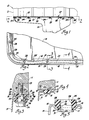
- Figure l is a fragmentary elevational view showing the lower portion of an engine assembly having a frame-carried oil pan with a vibration-isolation mounting and seal in conformity with the present invention;
- Figure 2 is a fragmentary sectional view, with parts in elevation, of the oil pan and seal assembly looking downwardly from the plane indicated by the
line 2--2 of Figure l, and thus in the direction of the arrows; - Figure 3 is a fragmentary transverse sectional view, with parts in elevation, through one of a plurality of fastener openings, from the plane of the
line 3--3 of Figure 2, in the direction of the arrows; - Figure 4 is a fragmentary transverse sectional view between fastener openings from the plane of the
line 4--4 of Figure 2, in the direction of the arrows; - Figure 5 is a fragmentary transverse cross-sectional view of the oil pan and seal assembly prior to its attachment to the engine frame;
- Figure 6 is a diametral cross-sectional view of a dished isolator washer of a type as shown in the assembly of Figure 3;
- Figure 7 is a view similar to Figure 3 but showing an alternative embodiment of an isolation mounting in conformity with the present invention;
- Figure 8 is a transverse cross-sectional view of a reversible seal configured for use in the isolation mounting shown in Figure 7; and
- Figure 9 is a diametral cross-sectional view of a flat isolator washer of a type as shown in the isolation mounting of Figure 7.
- With reference first to Figures l to 6 of the drawings, reference numeral l0 generally indicates an internal combustion engine having a frame ll including a generally flat oil pan-supporting lower surface l2 to which an oil pan l4 is attached by isolation mounting means in conformity with the present invention.
- The oil pan as shown is made of formed sheet steel, although other materials and methods of forming could be used if desired.
- The pan l4 is formed as an open-topped downwardly closed container terminating upwardly in an outwardly extending peripheral flange l5. The flange l5 has generally coplanar inner and outer upper edges l6,l8 respectively, lying along opposite sides of a recessed seal-receiving portion l9 that extends the length of the flange. The recessed portion l9 receives a
peripheral seal 20 and also stiffens the flange against bending by providing a dished (U-shaped) cross-section. A plurality of fastener-receivingopenings 22 pierce the flange in the recessed portion at spaced intervals around the periphery. In assembly, theopenings 22 align with corresponding threadedbores 23 in the frame ll, opening through the lower surface l2. - The
seal 20 is a continuous resilient vibration-absorbing member, preferably moulded from silicone rubber, or made in any suitable manner from any acceptable material. Theseal 20, which is seen in cross-section compressed in Figures 3 and 4 and uncompressed in Figure 5, has aflattened top 24 connected by means of slopingsides 26 to a flattened V-likelower portion 27 formed to fit within the recessed seal-receiving portion l9 of the flange l5. -
Fastener openings 28 extend through the seal l5 at locations aligned in assembly with the oil pan and engine block (frame) openings. - At each of the
fastener openings 28 in the seal l5, sleeve-liketubular extensions 30 create cylindrical portions extending downwardly from the seallower portion 27 and protruding, in assembly, through the oil-pan flange openings 22. Enlarged lower edges of thetubular extensions 30 preferably form sharp-edged grommet-like retainers 3l that are slightly larger in diameter than the oil-pan flange openings 22 and are deformable to pass therethrough In this manner the seal may be retained on the oil pan prior to and during assembly of the oil pan to the engine frame. The seal is preferably additionally provided withtubular inserts 32 moulded into thecylindrical extensions 30, to stiffen the extensions for when they are forced into the oil-pan flange openings 22. - In assembly, the oil pan l4 is secured to the lower surface l2 of the engine frame ll by means of fasteners in the form of
shoulder bolts 34, or equivalent bolt-sleeve assemblies, which pass through and engage rubber-metal isolator washers 35, thereby holding them in engagement with the lower side of the oil-pan flange l5. Thefastener bolts 34 also extend through the oil pan l4 and theopenings seal 20, and thence into engagement with the threadedbores 23 of the engine frame. The enlargedshoulders 36 of thebolts 34 engage the lower surface l2 of the engine frame to limit compression of theseal 20 and theisolator washers 35, so as to provide optimum vibration isolation of the oil pan from the engine frame ll. - The
isolator washers 35, as shown in Figure 6, are formed from dishedmetal washers 38 moulded with a rubber washer 39 between them. The openings through the rubber washers 39 and themoulded seal 20 are all smaller than the corresponding openings in themetal washers 38 and in the oil-pan flange l5, at least when the rubber portions are compressed in assembly, and preferably also prior to assembly, as seen in Figures 5 and 6. The contacting metal portions of the frame ll, thebolts 34 and thelower washers 38 are thereby positively isolated by rubber from the oil-pan flange l5 and from theupper washers 38 which the flange l5 contacts. - To assemble the oil pan l4 to the frame ll in the embodiment shown in Figures l to 6, the
seal 20 is first located in position on the oil-pan flange l5 and thetubular protrusions 30 are forced into the oil-pan openings 22, with the use of an insertion tool if necessary. Upon such insertion, the grommet-like retainers 3l expand to hold theseal 20 in place on the flange l5, as shown in Figure 5. The oil pan and seal assembly is then positioned against the frame surface l2, and thebolts 34 and thewashers 35 are installed and tightened. The recesses formed at the inner diameters of the dishedwashers 38 provide clearance for the seal retainers 3l, which extend below the oil-pan flange l5. - With reference now to Figures 7 to 9 of the drawings, there is shown an alternative embodiment of an isolation mounting applied to an engine generally indicated by
reference numeral 40. Like reference numerals are used for the illustrated portions of the engine frame ll, oil pan l4 andshoulder bolts 34, since they are unchanged from the first embodiment. The altered components comprise a resilient vibration-absorbingseal 42, which is shown separately in Figure 8, and isolator washers 43, which are shown separately in Figure 9. - The
resilient seal 42 includesangled sides 44 which interconnect identical flattened upper andlower portions 46 having spacedfastener openings 47 extending therethrough. Tubular protrusions forming sleeve-likecylindrical extensions 48 are provided on both the upper andlower portions 46 at each opening 47. Theseextensions 48 are long enough to protrude into the oil-pan flange openings 22, but either they do not extend through these openings or alternatively they do not extend very far through the openings. - The
seal 42 may be installed with eitherportion 46 against the oil-pan flange l5, since the fastener-receiving hole patterns are symmetrical. Theextensions 48 on the lower portion locate theseal 42 in the oil-pan openings. Theshoulder bolts 34 and the washers 43 are then installed. Since thefastener openings 47 in theseal 42 are made smaller than theshoulders 36 of thebolts 34, the bolts are gripped by the seal, thereby holding all the components in assembly while the oil pan is aligned with the engine frame ll and thebolts 34 are threaded into thebores 23. - The isolator washers 43 are made with
flat metal washers 50, since there is no need to provide clearance for seal retainers (not present in this embodiment). However, thedished washers 35 of the first embodiment could be substituted for the washers 43 if desired. - In assembly, as shown in Figure 7, the
bolts 34 compress theseal 42 by an amount that is controlled by the shoulder bolts but is sufficient to flatten theextensions 48 on the upper side (that is, the frame side) of theseal 42 while theextensions 48 on the lower, flange-engaged side protrude into theflange openings 22. - The rubber washers 5l of the isolator washers 43 are again made with smaller inner diameters than the
metal washers 50, to keep the bolts from grounding against (that is, contacting) themetal washers 50, and thus completely isolating the oil pan and frame by means of rubber members. - Thus in the embodiments which have been described, sleeve-like extensions 30 (48) extend through
openings 22 in the flange l5 to guide or position the seal 20 (42) on the flange and hold the edges of the flange away from contact with thebolts 34 that fix the oil pan l4 to the engine frame ll of the crankcase. - Additionally, isolator washers 35 (43) have rubber-washer centres 39 (5l) that engage the
bolts 34 to hold them away from the metal washers 38 (50) of the isolators. In the embodiment shown in Figures l to 6, retainers 3l formed by grommet-like enlargements help to hold the seal to the oil pan flange prior to assembly. The seal openings may be sized to grip the fasteners during asembly, to hold the bolts in place before tightening.
Claims (7)
Applications Claiming Priority (2)
| Application Number | Priority Date | Filing Date | Title |
|---|---|---|---|
| US06/836,552 US4667628A (en) | 1986-03-06 | 1986-03-06 | Oil pan isolation mounting and seal |
| US836552 | 1986-03-06 |
Publications (3)
| Publication Number | Publication Date |
|---|---|
| EP0237205A2 true EP0237205A2 (en) | 1987-09-16 |
| EP0237205A3 EP0237205A3 (en) | 1988-10-05 |
| EP0237205B1 EP0237205B1 (en) | 1991-04-17 |
Family
ID=25272209
Family Applications (1)
| Application Number | Title | Priority Date | Filing Date |
|---|---|---|---|
| EP87301342A Expired - Lifetime EP0237205B1 (en) | 1986-03-06 | 1987-02-17 | Oil pan isolation mounting and seal |
Country Status (5)
| Country | Link |
|---|---|
| US (1) | US4667628A (en) |
| EP (1) | EP0237205B1 (en) |
| JP (1) | JPH01104952A (en) |
| CA (1) | CA1287779C (en) |
| DE (1) | DE3769339D1 (en) |
Cited By (4)
| Publication number | Priority date | Publication date | Assignee | Title |
|---|---|---|---|---|
| DE3929592A1 (en) * | 1989-09-06 | 1991-03-28 | Man Nutzfahrzeuge Ag | SOUND-INSULATED SHEET OIL PAN FOR INTERNAL COMBUSTION ENGINES |
| EP0625636A1 (en) * | 1993-05-19 | 1994-11-23 | Ser Procal Gie | Hollow metallic piece with a seal gasket, like an oil sump of an internal combustion engine |
| US5368797A (en) * | 1991-12-17 | 1994-11-29 | Goetze Ag | Method for making a cover assembly for use on an internal combustion engine |
| EP0708235A1 (en) * | 1994-10-19 | 1996-04-24 | Ford-Werke Aktiengesellschaft | Fastening device for a cover on a machine |
Families Citing this family (23)
| Publication number | Priority date | Publication date | Assignee | Title |
|---|---|---|---|---|
| DE4010946A1 (en) * | 1989-11-30 | 1991-10-10 | Opel Adam Ag | OIL PAN FOR AN INTERNAL COMBUSTION ENGINE |
| US5044338A (en) * | 1990-01-23 | 1991-09-03 | Siemens Automotive L.P. | Fuel rail vibration damper |
| ATA108690A (en) * | 1990-05-16 | 1994-12-15 | Laimboeck Franz | LIQUID-COOLED INTERNAL COMBUSTION ENGINE |
| FR2671600B1 (en) * | 1991-01-10 | 1993-04-23 | Poclain Hydraulics Sa | MECHANISM HOUSING PROVIDED WITH PARTICULAR BLEEDING DEVICES. |
| GB2310694B (en) * | 1996-02-27 | 1999-12-08 | Aisin Seiki | Disc brake assembly |
| JP2759789B2 (en) * | 1996-06-03 | 1998-05-28 | 川崎重工業株式会社 | Small planing boat internal combustion engine |
| US5857503A (en) * | 1996-11-08 | 1999-01-12 | Transnav, Inc. | Apparatus and method for changing fluid in a motor vehicle |
| US6371073B1 (en) | 2000-11-02 | 2002-04-16 | Caterpillar Inc. | Isolated cover with independent sealing system |
| US6994354B2 (en) * | 2002-01-15 | 2006-02-07 | Freudenberg-Nok General Partnership | Vibrationally decoupling gasket |
| EP1375930B1 (en) * | 2002-06-18 | 2005-04-20 | BRP-Rotax GmbH & Co. KG | A vibration and noise dampening connection mechanism for connecting a pair of mechanical components |
| FR2855846B1 (en) * | 2003-06-03 | 2007-04-06 | Meillor Sa | CARTER WITH SOFT SHIRT |
| JP2005119434A (en) * | 2003-10-16 | 2005-05-12 | Honda Motor Co Ltd | Automobile guard pipe |
| US20050220564A1 (en) * | 2004-04-01 | 2005-10-06 | Hinson Kerry D | Fastener assembly with wave spring |
| US7641012B2 (en) | 2006-09-29 | 2010-01-05 | International Truck Intellectual Property Company, Llc | Module-locating fastener and method of mounting on a vehicle chassis |
| US7731443B2 (en) * | 2007-04-03 | 2010-06-08 | International Truck Intellectual Property Company, Llc | Mounting system for modular frame components |
| DE102007032649A1 (en) * | 2007-07-13 | 2009-01-15 | Man Nutzfahrzeuge Ag | Tub and method for its manufacture |
| WO2014131010A1 (en) * | 2013-02-25 | 2014-08-28 | Shiloh Industries, Inc. | Modular assembly having press-fit fastener holes |
| JP5969428B2 (en) * | 2013-06-27 | 2016-08-17 | トヨタ自動車株式会社 | Oil pan |
| JP6127879B2 (en) * | 2013-09-30 | 2017-05-17 | アイシン・エィ・ダブリュ株式会社 | Oil pan with seal |
| CN106593644A (en) * | 2016-12-26 | 2017-04-26 | 重庆小康工业集团股份有限公司 | Dust-proof plate installation structure |
| US10072541B2 (en) * | 2017-01-04 | 2018-09-11 | GM Global Technology Operations LLC | Oil pan assembly |
| US10683885B2 (en) * | 2017-07-19 | 2020-06-16 | GM Global Technology Operations LLC | Dual purpose threaded insert/compression limiter |
| CN109209553B (en) * | 2018-09-07 | 2019-10-29 | 浙江工贸职业技术学院 | A kind of internal combustion engine oil sump attachment device |
Citations (4)
| Publication number | Priority date | Publication date | Assignee | Title |
|---|---|---|---|---|
| FR2357736A1 (en) * | 1976-07-08 | 1978-02-03 | Saurer Ag Adolph | INTERNAL COMBUSTION ENGINE WITH LOWER CASING CONNECTED TO THE CRANKSHAFT WITH ACOUSTIC INSULATION OF THE ELEMENTS |
| FR2398887A1 (en) * | 1977-08-22 | 1979-02-23 | Toyo Kogyo Co | INTERNAL COMBUSTION ENGINE WITH ELASTICALLY FIXED OIL PAN |
| GB2052388A (en) * | 1979-06-02 | 1981-01-28 | Nissan Motor | Noise reducing cover for an internal combustion engine |
| JPS593117A (en) * | 1982-06-28 | 1984-01-09 | Mazda Motor Corp | Noise reducing construction for engine cover |
Family Cites Families (10)
| Publication number | Priority date | Publication date | Assignee | Title |
|---|---|---|---|---|
| AT278448B (en) * | 1967-08-21 | 1970-01-26 | H C Hans Dipl Ing Dr Dr List | Internal combustion engine with noise-absorbing casing |
| US4027644A (en) * | 1975-06-26 | 1977-06-07 | Cummins Engine Company, Inc. | Isolated engine cover |
| JPS546737A (en) * | 1977-06-17 | 1979-01-19 | Nec Corp | Refresh unit of memory device |
| DE2746740A1 (en) * | 1977-10-18 | 1979-04-26 | Volkswagenwerk Ag | SOUND-INSULATING ENCLOSED COMBUSTION MACHINE |
| US4445584A (en) * | 1978-04-12 | 1984-05-01 | Nissan Motor Co., Ltd. | Motor vehicle equipped with engine noise emission preventing device |
| JPS5529712A (en) * | 1978-08-23 | 1980-03-03 | Nissan Motor Co Ltd | Display unit for vehicle |
| US4394853A (en) * | 1981-06-22 | 1983-07-26 | General Motors Corporation | Engine oil pan isolation mounting |
| JPS5812658U (en) * | 1981-07-16 | 1983-01-26 | 日産自動車株式会社 | Rotsuka cover |
| US4423707A (en) * | 1982-09-24 | 1984-01-03 | Sihon Tanas M | Engine with internal crankcase bridge having integral oil pump and drive housing |
| JPS6081511A (en) * | 1983-10-06 | 1985-05-09 | 住友電気工業株式会社 | Washer |
-
1986
- 1986-03-06 US US06/836,552 patent/US4667628A/en not_active Expired - Fee Related
-
1987
- 1987-02-17 EP EP87301342A patent/EP0237205B1/en not_active Expired - Lifetime
- 1987-02-17 DE DE8787301342T patent/DE3769339D1/en not_active Expired - Fee Related
- 1987-02-20 CA CA000530170A patent/CA1287779C/en not_active Expired
- 1987-03-06 JP JP62051823A patent/JPH01104952A/en active Pending
Patent Citations (4)
| Publication number | Priority date | Publication date | Assignee | Title |
|---|---|---|---|---|
| FR2357736A1 (en) * | 1976-07-08 | 1978-02-03 | Saurer Ag Adolph | INTERNAL COMBUSTION ENGINE WITH LOWER CASING CONNECTED TO THE CRANKSHAFT WITH ACOUSTIC INSULATION OF THE ELEMENTS |
| FR2398887A1 (en) * | 1977-08-22 | 1979-02-23 | Toyo Kogyo Co | INTERNAL COMBUSTION ENGINE WITH ELASTICALLY FIXED OIL PAN |
| GB2052388A (en) * | 1979-06-02 | 1981-01-28 | Nissan Motor | Noise reducing cover for an internal combustion engine |
| JPS593117A (en) * | 1982-06-28 | 1984-01-09 | Mazda Motor Corp | Noise reducing construction for engine cover |
Non-Patent Citations (1)
| Title |
|---|
| PATENT ABSTRACTS OF JAPAN, vol. 8, no. 87 (M-291)[1524], 20th April 1984; & JP-A-59 003 117 (TOYO KOGYO K.K.) 09-01-1984 * |
Cited By (5)
| Publication number | Priority date | Publication date | Assignee | Title |
|---|---|---|---|---|
| DE3929592A1 (en) * | 1989-09-06 | 1991-03-28 | Man Nutzfahrzeuge Ag | SOUND-INSULATED SHEET OIL PAN FOR INTERNAL COMBUSTION ENGINES |
| US5368797A (en) * | 1991-12-17 | 1994-11-29 | Goetze Ag | Method for making a cover assembly for use on an internal combustion engine |
| EP0625636A1 (en) * | 1993-05-19 | 1994-11-23 | Ser Procal Gie | Hollow metallic piece with a seal gasket, like an oil sump of an internal combustion engine |
| FR2705407A1 (en) * | 1993-05-19 | 1994-11-25 | Ser Procal Gie | Hollow metal part provided with a seal, such as a motor vehicle engine crankcase. |
| EP0708235A1 (en) * | 1994-10-19 | 1996-04-24 | Ford-Werke Aktiengesellschaft | Fastening device for a cover on a machine |
Also Published As
| Publication number | Publication date |
|---|---|
| EP0237205B1 (en) | 1991-04-17 |
| DE3769339D1 (en) | 1991-05-23 |
| US4667628A (en) | 1987-05-26 |
| JPH01104952A (en) | 1989-04-21 |
| CA1287779C (en) | 1991-08-20 |
| EP0237205A3 (en) | 1988-10-05 |
Similar Documents
| Publication | Publication Date | Title |
|---|---|---|
| EP0237205B1 (en) | Oil pan isolation mounting and seal | |
| US4394853A (en) | Engine oil pan isolation mounting | |
| CA1056412A (en) | Vibration isolation system | |
| US4597583A (en) | Gasket assembly for sealing covers to automotive engines | |
| US6227784B1 (en) | Fastener assembly with vibration isolating features | |
| US5428895A (en) | Method of manufacturing sealing gasket with hard interior backbone and integral crush limiters | |
| US4867461A (en) | Gasket sealing system | |
| US6039323A (en) | Rubber molded gasket with compression limiter | |
| KR101510139B1 (en) | Vehicle engine and snap-on engine cover assembly therefor and method of assembly of the cover assembly to the engine | |
| JPS6018867B2 (en) | Vibration isolation/sealing gasket | |
| JPS63306260A (en) | Gasket sub-assembly | |
| EP0261485A1 (en) | Gasket assembly for oil pan valve covers and the like | |
| US4619343A (en) | Noise-isolated fastening of an oil sump to a crankcase | |
| US6435297B1 (en) | Vehicle component mounting assembly | |
| US4719892A (en) | Cavity closure with isolator seal and method | |
| EP0020383B1 (en) | Vibration and dust isolation system | |
| EP0416297B1 (en) | Noise damped sheet oil sump for an internal combustion engine | |
| US6508471B1 (en) | Gasket with molded-in bolt retention means | |
| US4101003A (en) | Isolated oil pan assembly | |
| DE69837779T2 (en) | ENGINE | |
| US5724865A (en) | Caseless transmission structure | |
| GB2106612A (en) | Vibration-isolating resilient interlayers | |
| EP0046923A2 (en) | Noise reducing cover | |
| US6213477B1 (en) | Metal cylinder head gasket with portion for holding intermediate area between cylinder bores | |
| JPS6027804Y2 (en) | Cylinder head cover used in internal combustion engines |
Legal Events
| Date | Code | Title | Description |
|---|---|---|---|
| PUAI | Public reference made under article 153(3) epc to a published international application that has entered the european phase |
Free format text: ORIGINAL CODE: 0009012 |
|
| 17P | Request for examination filed |
Effective date: 19870302 |
|
| AK | Designated contracting states |
Kind code of ref document: A2 Designated state(s): DE FR GB |
|
| PUAL | Search report despatched |
Free format text: ORIGINAL CODE: 0009013 |
|
| AK | Designated contracting states |
Kind code of ref document: A3 Designated state(s): DE FR GB |
|
| RAP1 | Party data changed (applicant data changed or rights of an application transferred) |
Owner name: DETROIT DIESEL CORPORATION (DELAWARE CORP.) |
|
| 17Q | First examination report despatched |
Effective date: 19900112 |
|
| GRAA | (expected) grant |
Free format text: ORIGINAL CODE: 0009210 |
|
| AK | Designated contracting states |
Kind code of ref document: B1 Designated state(s): DE FR GB |
|
| REF | Corresponds to: |
Ref document number: 3769339 Country of ref document: DE Date of ref document: 19910523 |
|
| ET | Fr: translation filed | ||
| PLBE | No opposition filed within time limit |
Free format text: ORIGINAL CODE: 0009261 |
|
| STAA | Information on the status of an ep patent application or granted ep patent |
Free format text: STATUS: NO OPPOSITION FILED WITHIN TIME LIMIT |
|
| 26N | No opposition filed | ||
| PGFP | Annual fee paid to national office [announced via postgrant information from national office to epo] |
Ref country code: GB Payment date: 19950207 Year of fee payment: 9 |
|
| PGFP | Annual fee paid to national office [announced via postgrant information from national office to epo] |
Ref country code: DE Payment date: 19950209 Year of fee payment: 9 |
|
| PGFP | Annual fee paid to national office [announced via postgrant information from national office to epo] |
Ref country code: FR Payment date: 19950210 Year of fee payment: 9 |
|
| PG25 | Lapsed in a contracting state [announced via postgrant information from national office to epo] |
Ref country code: GB Effective date: 19960217 |
|
| GBPC | Gb: european patent ceased through non-payment of renewal fee |
Effective date: 19960217 |
|
| PG25 | Lapsed in a contracting state [announced via postgrant information from national office to epo] |
Ref country code: FR Effective date: 19961031 |
|
| PG25 | Lapsed in a contracting state [announced via postgrant information from national office to epo] |
Ref country code: DE Effective date: 19961101 |
|
| REG | Reference to a national code |
Ref country code: FR Ref legal event code: ST |