EP0237183A1 - Torch for fabricating optical fibre preform - Google Patents
Torch for fabricating optical fibre preform Download PDFInfo
- Publication number
- EP0237183A1 EP0237183A1 EP87301129A EP87301129A EP0237183A1 EP 0237183 A1 EP0237183 A1 EP 0237183A1 EP 87301129 A EP87301129 A EP 87301129A EP 87301129 A EP87301129 A EP 87301129A EP 0237183 A1 EP0237183 A1 EP 0237183A1
- Authority
- EP
- European Patent Office
- Prior art keywords
- gas injection
- injection passage
- torch
- annular
- combustion supporting
- Prior art date
- Legal status (The legal status is an assumption and is not a legal conclusion. Google has not performed a legal analysis and makes no representation as to the accuracy of the status listed.)
- Granted
Links
Images

Classifications
-
- C—CHEMISTRY; METALLURGY
- C03—GLASS; MINERAL OR SLAG WOOL
- C03B—MANUFACTURE, SHAPING, OR SUPPLEMENTARY PROCESSES
- C03B37/00—Manufacture or treatment of flakes, fibres, or filaments from softened glass, minerals, or slags
- C03B37/01—Manufacture of glass fibres or filaments
- C03B37/012—Manufacture of preforms for drawing fibres or filaments
- C03B37/014—Manufacture of preforms for drawing fibres or filaments made entirely or partially by chemical means, e.g. vapour phase deposition of bulk porous glass either by outside vapour deposition [OVD], or by outside vapour phase oxidation [OVPO] or by vapour axial deposition [VAD]
- C03B37/01413—Reactant delivery systems
- C03B37/0142—Reactant deposition burners
-
- C—CHEMISTRY; METALLURGY
- C03—GLASS; MINERAL OR SLAG WOOL
- C03B—MANUFACTURE, SHAPING, OR SUPPLEMENTARY PROCESSES
- C03B2207/00—Glass deposition burners
- C03B2207/04—Multi-nested ports
- C03B2207/06—Concentric circular ports
-
- C—CHEMISTRY; METALLURGY
- C03—GLASS; MINERAL OR SLAG WOOL
- C03B—MANUFACTURE, SHAPING, OR SUPPLEMENTARY PROCESSES
- C03B2207/00—Glass deposition burners
- C03B2207/04—Multi-nested ports
- C03B2207/08—Recessed or protruding ports
-
- C—CHEMISTRY; METALLURGY
- C03—GLASS; MINERAL OR SLAG WOOL
- C03B—MANUFACTURE, SHAPING, OR SUPPLEMENTARY PROCESSES
- C03B2207/00—Glass deposition burners
- C03B2207/04—Multi-nested ports
- C03B2207/12—Nozzle or orifice plates
-
- C—CHEMISTRY; METALLURGY
- C03—GLASS; MINERAL OR SLAG WOOL
- C03B—MANUFACTURE, SHAPING, OR SUPPLEMENTARY PROCESSES
- C03B2207/00—Glass deposition burners
- C03B2207/04—Multi-nested ports
- C03B2207/14—Tapered or flared nozzles or ports angled to central burner axis
-
- C—CHEMISTRY; METALLURGY
- C03—GLASS; MINERAL OR SLAG WOOL
- C03B—MANUFACTURE, SHAPING, OR SUPPLEMENTARY PROCESSES
- C03B2207/00—Glass deposition burners
- C03B2207/04—Multi-nested ports
- C03B2207/16—Non-circular ports, e.g. square or oval
-
- C—CHEMISTRY; METALLURGY
- C03—GLASS; MINERAL OR SLAG WOOL
- C03B—MANUFACTURE, SHAPING, OR SUPPLEMENTARY PROCESSES
- C03B2207/00—Glass deposition burners
- C03B2207/20—Specific substances in specified ports, e.g. all gas flows specified
-
- C—CHEMISTRY; METALLURGY
- C03—GLASS; MINERAL OR SLAG WOOL
- C03B—MANUFACTURE, SHAPING, OR SUPPLEMENTARY PROCESSES
- C03B2207/00—Glass deposition burners
- C03B2207/20—Specific substances in specified ports, e.g. all gas flows specified
- C03B2207/22—Inert gas details
-
- C—CHEMISTRY; METALLURGY
- C03—GLASS; MINERAL OR SLAG WOOL
- C03B—MANUFACTURE, SHAPING, OR SUPPLEMENTARY PROCESSES
- C03B2207/00—Glass deposition burners
- C03B2207/20—Specific substances in specified ports, e.g. all gas flows specified
- C03B2207/26—Multiple ports for glass precursor
-
- C—CHEMISTRY; METALLURGY
- C03—GLASS; MINERAL OR SLAG WOOL
- C03B—MANUFACTURE, SHAPING, OR SUPPLEMENTARY PROCESSES
- C03B2207/00—Glass deposition burners
- C03B2207/36—Fuel or oxidant details, e.g. flow rate, flow rate ratio, fuel additives
-
- C—CHEMISTRY; METALLURGY
- C03—GLASS; MINERAL OR SLAG WOOL
- C03B—MANUFACTURE, SHAPING, OR SUPPLEMENTARY PROCESSES
- C03B2207/00—Glass deposition burners
- C03B2207/42—Assembly details; Material or dimensions of burner; Manifolds or supports
Definitions
- This invention relates to a torch for fabricating an optical fiber preform in case of manufacturing a porous glass preform for a communication or optics through a VAD method or an OVD method.
- a VAD method or an OVD method which mixes less impurities and OH group is employed as means for fabricating a porous glass preform for an optical fiber, an image fiber, a light guide or a rod lens.
- Each of the above-mentioned methods supplies raw gas, combustible gas and combustion supporting gas or these gases and sealing gas to a torch for fabricating a porous glass preform, produces soot-state porous glass preform by flame hydrolysis and/or thermal oxidation, and accumulates the preform in a desired shape such as a rod or tube shape.
- a torch used in these methods has a multiwall tube structure of triple or more wall tubes.
- the passages from the center to the outermost periphery of the torch are used as a raw gas injection passage (first passage: at the center), a sealing gas injection passage (second passage), a combustible gas injection passage (third passage) and a combustion supporting gas injection passage (fourth passage: the outermost periphery).
- the raw gas contains SiC1 4 of main raw gas, and GeCl 4 , POCl 3 , BCl 3 , of doping raw materials.
- the combustible gas contains hydrogen (H z ), methane, propane, butane or a mixture gas of any two or more gases.
- the combustion supporting gas contains oxygen (O z ), and the sealing gas contains Ar and/or other inert gas.
- VAD and OVD methods Principles of accumulating the optical fiber preforms in the VAD and OVD methods are fundamentally the same, but the VAD method accumulates the optical fiber preform on the lower end of a vertical target drawn while rotating, and the OVD method accumulates the optical fiber preform on the outer periphery of a mandrel rotating in a horizontal state.
- porous glass preform thus accumulated and formed through the above methods is dehydrated and transparently vitrified by the following heat treatment to become a transparent preform which contains no air bubble.
- the porous glass preform is grown axially by the accumulation of the optical fiber preform.
- a large own weight is applied to the preform.
- the preform tends to be damaged by the weight of itself.
- the shrink-fitting degree of the porous glass preform becomes insufficient toward the end of the accumulation due to such a phenomenon so that there is a difference in the density of the optical fiber preform over the radial direction of the preform between the central portion and the peripheral portion.
- the density of the porous glass preform is perferably 0,4 to 1.0 g/cn 3 . If the density of the porous glass preform decreases below this value due to the insufficient shrink-fitting degree, a crack occurs in the preform along the longitudinal direction of the preform at growing or cooling time.
- this method depends upon an uncertain process of setting experimentally the increasing amount of the gas and is very difficult to gradually increase the combustible gas to eliminate the uneven accumulating density of the optical fiber preform by preventing the preform from cracking when considering that a flame generated from a torch is of a converging shape.
- the method of fabricating the porous glass preform with a conventional torque of multiwall tube structure can hardly provide a large-size preform having uniform optical fiber preform density without crack nor improper outer diameter.
- an object of this invention is to provide a torch for fabricating an optical fiber preform capable of stably manufacturing a porous glass preform.
- a torch for fabricating an optical fiber preform comprising a plurality of raw gas injection passages at the center of the torch, a plurality of small-diameter combustion supporting gas injection passages independent of each other and disposed to surround the raw gas injection passages on the outer periphery of the raw gas injection passage disposed at the center of the torch, and an annular combustible gas injection passage provided on the periphery of each of the small-diameter combustion supporting gas injection passages.
- a torch for fabricating an optical fiber preform comprising a. plurality of raw gas injection passages at the center of the torch, a plurality of small-diameter combustion supporting gas injection passages independent of each other and disposed to surround the raw gas injection passages on the outer periphery of the raw gas injection passages disposed at the center of the torch, an annular combustible gas injection passage provided on the periphery of each of the small-diameter combustion supporting gas injection passages, and an annular combustion supporting gas injection passage provided on the outer periphery of the annular combustion gas injection passage.
- a torch for fabricating an optical fiber preform comprising a plurality of raw gas injection passages at the center of the torch, a first annular sealing gas injection passage provided on the outer periphery of the raw gas injection passage disposed at the center of the torch, a plurality of small-diameter combustion supporting gas injection passages independent of each other and disposed to surround the annular sealing gas injection passage on the outer periphery of the first annular sealing gas injection passage, an annular combustible gas injection passage provided on the periphery of each of the small-diameter combustion supporting gas injection passages, a second sealing gas injection passage provided on the outer periphery of the-annular combustible gas injection passage, and an annular combustion supporting gas injection passage provided on the outer periphery of the second sealing gas injection passage.
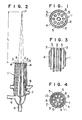
- FIGs. 1 and 2 show a first embodiment of a torch according to the present invention.
- a torch 1 of a multiwall tube structure shown in Figs. 1 and 2 has a raw gas injection passage 2 provided at the center of the torch 1, an annular combustible gas injection passage 3 provided on the outer periphery of the raw gas injection passage 2, an annular combustion supporting gas injection passage 4 provided on the outer periphery of the combustible gas injection passage 3, and a plurality of small-diameter combustion supporting gas injection passages 5 independent of each other and provided at an (equal) interval circumferentially in the combustible gas injection passage 3.
- the small-diameter combustion supporting gas injection passages 5 disposed in the combustion gas injection passage 3 surround the raw gas injection passage 2 disposed at the center of the torch 1.
- small-diameter combustion supporting gas injection passages 5 are, as apparent from Fig. 2, directed toward a point P on the center line of the raw gas injection passage 2, of so-called a focus converging type.
- gas inlets 6, 7, 8 and 9 are provided correspondingly to the gas injection passages 2, 3, 4 and 5 at the lower portion of the torch 1.
- a torch 1 of multiwall tube structure of a second embodiment of the invention shown in Fig. 3 is constructed fundamentally the same as that in Figs. 1 and 2 except a raw gas injection passage 2, an annular combustible gas injection passage 3, an annular combustion supporting gas injection passage 4 and a small-diameter combustion supporting gas injection passage 5 are disposed in parallel with each other and t'hat the injection passages 3, 5, 2 and 4 are sequentially protruded at the ends in the relative relationship of the passages.
- the ends of the raw gas injection passage 2 and the small-diameter combustion supporting gas injection passage 5 are formed in spherical shape.
- annular combustion supporting gas injection passage 4 may be omitted within the spirit and scope of the invention.
- a torch 1 of multiwall tube structure of a third embodiment of the invention shown in Fig. 4 is constructed such that a raw gas injection passage 2, a first annular sealing gas injection passage 10, an annular combustible gas injection passage 3, a second annular sealing gas injection passage 11 and an annular combustion supporting gas injection passage 4 are sequentially provided from the center of the torch 1 toward the outer periphery and a plurality of small-diameter combustion supporting gas injection passages 5 independent of each other are provided at an interval in the circumferential direction within the annular combustion gas injection passage 3.
- a plurality of raw gas injection passages and/or a plurality of combustible gas injection passages may be provided.
- annular combustible gas injection passages When two annular combustible gas injection passages are provided, one may be disposed at the position in the previous embodiments, and the other may be disposed, for example, on the outermost periphery of the torch 1.
- the tubular or cylindrical material of the torch 1 is formed of a quartz glass or ceramics having high heat resistance, and may also be formed at the end sides of the gas injection passages of a quartz glass or ceramics and at the remainder of a metal having excellent corrosion resistance and medicine resistance.
- Figs. 5 and 6 schematically show a VAD method and an OVD method executed by the torch 1 of the invention.
- a system has a reaction vessel 21 which contains an exhaust conduit 22, an electric furnace 23 which contains a heater (an electric heater) 24 provided at the top of the vessel 21, a target 25 of quartz and a rotary drawing unit 26 of the target 25.
- an optical fiber preform produced through the torch 1 is sequentially acccumulated on the lower end of the target 25 to form a porous glass preform 27, the porous glass preform 27 is transparently vitrified through the electric furnace 23 to provide a rod-shaped transparent glass preform 28.
- this system has a rotating and reciprocating type drive unit 31, and a mandrel 32 of quartz pipe supported by the drive unit 31.
- an optical fiber preform produced through the torch 1 is sequentially accumulated on the outer periphery of the mandrel 32 to provide a tubular porous glass preform 33.
- the raw gas, the combustible gas, the combustion supporting gas and the sealing gas used in the above-mentioned VAD and OVD methods employ those known per se.
- the torch 1 of the present invention is used in the above VAD and OVD methods as described above.
- the raw gas injected from the raw gas injection gas 2 is subjected to a flame hydrolysis and/or thermal oxidation with the combustible gas from the annular combustible gas injection passage 3 and the combustion supporting gas from the small-diameter combustion supporting gas injection passage 5 to become a soot-state optical fiber preform.
- the small-diameter combustion supporting injection passage 5 is formed in a nozzle shape, the combustion supporting gas injected from the small-diameter combustion supporting gas injection passage 5 flows at a very high speed.
- the combustion reaction of the combustible gas injected from the annular combustible gas injection passage 3 disposed around the small-diameter combustion supporting gas injection passage 5 with the combustion supporting gas is accelerated to increase the combustion amount, thereby providing an extremely higher temperature than a conventional multiwall tube burner. Therefore, the accumulation of the optical fiber preform is accelerated. Since the surface temperature of the porous glass preform formed by the accumulation of the optical fiber preform is very high and can be. maintained at a uniform value, the optical fiber preform of the porous glass preform is uniformly and sufficiently shrink-fitted so that the porous glass preform of substantially uniform density of the optical fiber preform can be provided.
- the combustion supporting gas is injected from the small- iameter combustion supporting gas injection passages 5 and the ombustible gas such as hydrogen is injected from the annular ombustible gas injection passage 3 in the torch 1 of the invention, ifferent from the case that the hydrogen and the oxygen are njected together in the preliminarily mixed state, a flame is ormed at a position separate at a predetermined distance from the and of the torch 1. More specifically, since the flowing speed of he combustion supporting gas is accelerated as described above in ;his invention, a flame can be formed at the position separate from he end of the torch 1.
- the ends of the raw back injection passage 2 and the small-diameter combustion supporting gas injection passage 5 are formed of spherical shape, it can preferably prevent the optical fiber preform from being bonded to the end of the torch 1.
- the first annular sealing gas injection passage 10 has an effect of preventing the raw gas injection passage 2 from being blocked by the optical fiber preform and the second annular sealing gas injection passage 11 protects against the thermal deformation of the end of the tubular or cylindrical member for partitioning the annular combustible gas injection passage 3 and the annular combustion supporting gas injection passage 4.
- the combustion supporting gas injected from the annular combustion supporting gas injection passage 4 contributes to the stability of a flame without direct relation to the synthesis of the optical fiber preform.
- the flame is uniformly formed in the temperature distribution over the center and the periphery. As a result, it can prevent the surface of the porous glass preform from becoming uneven, and additionally equalize the density of the optical fiber preform.
- the combustion supporting gas injected from the annular combustion supporting gas injection passage 4 interrupts the contact of the atmosphere with the combustible gas injected from the inside annular combustible gas injection passage 3 to allow the remaining unburnt combustible gas to be completely burnt by the combustion supporting gas. In other words, it prevents the remaining unburnt combustible gas injected from the inside annular combustion gas injection passage 3 from being subjected to an unstable combustion with oxygen in the air so that a disorder in the periphery of the flame is induced.
- the OVD method of Fig. 6 was executed under the following conditions with the torch 1 in Figs. 1 and 2.
- Combustible gas injection passage 3 Combustible gas injection passage 3 :
- Combustion supporting gas injection passage 4 Combustion supporting gas injection passage 4 :
- Combustion supporting gas injection passage 5 Combustion supporting gas injection passage 5 :
- the torch for fabricating the optical fiber preform in accordance with the invention disposes the small-diameter combustion supporting gas injection passages independent of each other and disposed to surround the raw gas injection passage on the outer periphery of the raw gas injection passage disposed at the center of the torch, and provides the annular combustible gas injection passage around the small-diameter combustion supporting gas injection passages. Accordingly, the porous glass preform can be stably fabricated by the specific arrangement of the small-diameter combustion supporting gas injection passages.
- the torch for fabricating the optical fiber preform further disposes in the first embodiment the annular combustion supporting gas injection passage on the outer periphery of the annular combustible gas injection passage. Therefore, the torch of this embodiment can not only provide the above-mentioned advantages, but stabilize the flame through the annular combustion supporting gas injection passage over the entire radial direction.
- the torch for fabricating the optical fiber preform further disposes in the above first and second embodiments the first and the second annular sealing gas injection passages between the predetermined gas injection passages. Consequently, the torch of this embodiment can not only provide the above-mentioned advantages, but prevent the raw gas injection passage from clogging by the optical fiber preform to protect the end of the tubular or cylindrical member for partitioning the annular combustible gas injection passage and the annular combustion supporting gas injection passage.
Abstract
Description
- This invention relates to a torch for fabricating an optical fiber preform in case of manufacturing a porous glass preform for a communication or optics through a VAD method or an OVD method.
- A VAD method or an OVD method which mixes less impurities and OH group is employed as means for fabricating a porous glass preform for an optical fiber, an image fiber, a light guide or a rod lens.
- Each of the above-mentioned methods supplies raw gas, combustible gas and combustion supporting gas or these gases and sealing gas to a torch for fabricating a porous glass preform, produces soot-state porous glass preform by flame hydrolysis and/or thermal oxidation, and accumulates the preform in a desired shape such as a rod or tube shape.
- A torch used in these methods has a multiwall tube structure of triple or more wall tubes. When the torch is formed, for example, of a quadruple wall tube structure, the passages from the center to the outermost periphery of the torch are used as a raw gas injection passage (first passage: at the center), a sealing gas injection passage (second passage), a combustible gas injection passage (third passage) and a combustion supporting gas injection passage (fourth passage: the outermost periphery).
- The raw gas contains SiC14 of main raw gas, and GeCl4, POCl3, BCl3, of doping raw materials. The combustible gas contains hydrogen (Hz), methane, propane, butane or a mixture gas of any two or more gases. The combustion supporting gas contains oxygen (Oz), and the sealing gas contains Ar and/or other inert gas.
- Principles of accumulating the optical fiber preforms in the VAD and OVD methods are fundamentally the same, but the VAD method accumulates the optical fiber preform on the lower end of a vertical target drawn while rotating, and the OVD method accumulates the optical fiber preform on the outer periphery of a mandrel rotating in a horizontal state.
- The porous glass preform thus accumulated and formed through the above methods is dehydrated and transparently vitrified by the following heat treatment to become a transparent preform which contains no air bubble.
- In case of the above-mentioned VAD method, the porous glass preform is grown axially by the accumulation of the optical fiber preform. In this case, as the preform is grown, a large own weight is applied to the preform. Thus, when a long and large porous glass preform is produced, the preform tends to be damaged by the weight of itself.
- Therefore, it is necessary to improve the strength of the preform to enhance the accumulating density of the optical fiber preform when fabricating the large-size porous glass preform by the VAD method.
- In case of the OVD method for accumulating an optical fiber preform on the outer periphery of a mandrel of horizontal state, no damage occurs in the porous glass preform as observed in the VAD method, but as the optical fiber preform is accumulated, the diameter of the preform increases so that the surface area of the preform gradually increases. Thus, the quantity of heat of unit area/unit time of a flame generated from a torch to the surface of the preform alters, and the quantity of heat at the end of accumulating the optical fiber preform becomes considerably smaller than that at the initial time.
- The shrink-fitting degree of the porous glass preform becomes insufficient toward the end of the accumulation due to such a phenomenon so that there is a difference in the density of the optical fiber preform over the radial direction of the preform between the central portion and the peripheral portion.
- The density of the porous glass preform is perferably 0,4 to 1.0 g/cn3. If the density of the porous glass preform decreases below this value due to the insufficient shrink-fitting degree, a crack occurs in the preform along the longitudinal direction of the preform at growing or cooling time.
- To eliminate this drawback, the rotating speed of the preform is decelerated in response to the growth of the preform or the quantity of combustion gas is increases.
- However, in the former case that the rotating speed of the preform is decelerated, a cause of an uneven surface is produced on the surface of the porous glass preform or an improper outer diameter is produced in the preform.
- In the latter case that the quantity of combustion gas is increased, this method depends upon an uncertain process of setting experimentally the increasing amount of the gas and is very difficult to gradually increase the combustible gas to eliminate the uneven accumulating density of the optical fiber preform by preventing the preform from cracking when considering that a flame generated from a torch is of a converging shape.
- As described above, the method of fabricating the porous glass preform with a conventional torque of multiwall tube structure can hardly provide a large-size preform having uniform optical fiber preform density without crack nor improper outer diameter.
- Accordingly, an object of this invention is to provide a torch for fabricating an optical fiber preform capable of stably manufacturing a porous glass preform.
- In order to achieve the above and other objects of this invention, there is provided according to an aspect of this invention a torch for fabricating an optical fiber preform comprising a plurality of raw gas injection passages at the center of the torch, a plurality of small-diameter combustion supporting gas injection passages independent of each other and disposed to surround the raw gas injection passages on the outer periphery of the raw gas injection passage disposed at the center of the torch, and an annular combustible gas injection passage provided on the periphery of each of the small-diameter combustion supporting gas injection passages.
- According to another aspect of this invention, there is provided to achieve the above and other objects of this invention a torch for fabricating an optical fiber preform comprising a. plurality of raw gas injection passages at the center of the torch, a plurality of small-diameter combustion supporting gas injection passages independent of each other and disposed to surround the raw gas injection passages on the outer periphery of the raw gas injection passages disposed at the center of the torch, an annular combustible gas injection passage provided on the periphery of each of the small-diameter combustion supporting gas injection passages, and an annular combustion supporting gas injection passage provided on the outer periphery of the annular combustion gas injection passage.
- According to still another aspect of this invention, there is provided to achieve the above and other objects of the invention a torch for fabricating an optical fiber preform comprising a plurality of raw gas injection passages at the center of the torch, a first annular sealing gas injection passage provided on the outer periphery of the raw gas injection passage disposed at the center of the torch, a plurality of small-diameter combustion supporting gas injection passages independent of each other and disposed to surround the annular sealing gas injection passage on the outer periphery of the first annular sealing gas injection passage, an annular combustible gas injection passage provided on the periphery of each of the small-diameter combustion supporting gas injection passages, a second sealing gas injection passage provided on the outer periphery of the-annular combustible gas injection passage, and an annular combustion supporting gas injection passage provided on the outer periphery of the second sealing gas injection passage.
- The above and other related objects and features of the invention will'be apparent from a reading of the following description of the disclosure found in the accompanying drawings and the novelty thereof pointed out in the appended claims.
- Fig. 1 is a plan view showing a first embodiment of a torch according to the present invention;
- Fig. 2 is a longitudinal sectional view of the torch of Fig. 1;
- Fig. 3 is a longitudinal sectional view of an essential portion of a second embodiment of a torch according to the present invention;
- Fig. 4 is a plan view showing a third embodiment of a torch according to the invention;
- Fig. 5 is a schematic view showing a VAD method using the torch of the invention; and
- Fig. 6 is a schematic view showing an OVD method using the torch of the invention.
- Embodiments of a torch for fabricating an optical fiber preform according to the present invention will be described in detail with reference to the accompanying drawings.
- Figs. 1 and 2 show a first embodiment of a torch according to the present invention. A torch 1 of a multiwall tube structure shown in Figs. 1 and 2 has a raw
gas injection passage 2 provided at the center of the torch 1, an annular combustiblegas injection passage 3 provided on the outer periphery of the rawgas injection passage 2, an annular combustion supportinggas injection passage 4 provided on the outer periphery of the combustiblegas injection passage 3, and a plurality of small-diameter combustion supportinggas injection passages 5 independent of each other and provided at an (equal) interval circumferentially in the combustiblegas injection passage 3. - In case of such a torch 1, as apparent from Fig. 1, the small-diameter combustion supporting
gas injection passages 5 disposed in the combustiongas injection passage 3 surround the rawgas injection passage 2 disposed at the center of the torch 1. - Further, the small-diameter combustion supporting
gas injection passages 5 are, as apparent from Fig. 2, directed toward a point P on the center line of the rawgas injection passage 2, of so-called a focus converging type. - A distance L from the end of the torch 1 to the point P is ordinarily set to a range of approx. 30 to 350 mm, and more particularly to L=approx. 200 mm.
- As shown in Fig. 2,
gas inlets gas injection passages - A torch 1 of multiwall tube structure of a second embodiment of the invention shown in Fig. 3 is constructed fundamentally the same as that in Figs. 1 and 2 except a raw
gas injection passage 2, an annular combustiblegas injection passage 3, an annular combustion supportinggas injection passage 4 and a small-diameter combustion supportinggas injection passage 5 are disposed in parallel with each other and t'hat theinjection passages - Further, in the torch 1 of Fig. 3, the ends of the raw
gas injection passage 2 and the small-diameter combustion supportinggas injection passage 5 are formed in spherical shape. - It is noted that the constructions of the difference (uneven state) of the projecting states of the ends of the injection passages or the spherical shape of the ends of the injection passages in the second embodiment of the invention may also be employed in the first embodiment in Figs. 1 and 2 and in the following third embodiment of the invention as will be described later within the spirit and scope of the invention.
- Further, it is also noted that in the torch 1 of the above-mentioned first and second embodiments, the annular combustion supporting
gas injection passage 4 may be omitted within the spirit and scope of the invention. - A torch 1 of multiwall tube structure of a third embodiment of the invention shown in Fig. 4 is constructed such that a raw
gas injection passage 2, a first annular sealinggas injection passage 10, an annular combustiblegas injection passage 3, a second annular sealing gas injection passage 11 and an annular combustion supportinggas injection passage 4 are sequentially provided from the center of the torch 1 toward the outer periphery and a plurality of small-diameter combustion supportinggas injection passages 5 independent of each other are provided at an interval in the circumferential direction within the annular combustiongas injection passage 3. - As further embodiments, a plurality of raw gas injection passages and/or a plurality of combustible gas injection passages may be provided.
- For example, in these embodiments, when two (or more) adjacent raw gas injection passages are provided at the center of the torch 1, other gas injection passages provided in a multiwall tube structure is formed in an elliptical shape on the outer periphery of the raw gas injection passage. When the small-diameter combustion supporting gas injection passages are formed in a focus converging type in this case, two focuses of the ellipse are defined to correspond to the small-diameter combustion supporting gas injection passages.
- When two annular combustible gas injection passages are provided, one may be disposed at the position in the previous embodiments, and the other may be disposed, for example, on the outermost periphery of the torch 1.
- The tubular or cylindrical material of the torch 1 is formed of a quartz glass or ceramics having high heat resistance, and may also be formed at the end sides of the gas injection passages of a quartz glass or ceramics and at the remainder of a metal having excellent corrosion resistance and medicine resistance.
- Figs. 5 and 6 schematically show a VAD method and an OVD method executed by the torch 1 of the invention.
- In the VAD method in Fig. 5, a system has a
reaction vessel 21 which contains anexhaust conduit 22, anelectric furnace 23 which contains a heater (an electric heater) 24 provided at the top of thevessel 21, atarget 25 of quartz and arotary drawing unit 26 of thetarget 25. According to the VAD method in this known system, an optical fiber preform produced through the torch 1 is sequentially acccumulated on the lower end of thetarget 25 to form aporous glass preform 27, theporous glass preform 27 is transparently vitrified through theelectric furnace 23 to provide a rod-shapedtransparent glass preform 28. - In the OVD method in Fig. 6, this system has a rotating and reciprocating
type drive unit 31, and amandrel 32 of quartz pipe supported by thedrive unit 31. According to the OVD method in this known system, an optical fiber preform produced through the torch 1 is sequentially accumulated on the outer periphery of themandrel 32 to provide a tubularporous glass preform 33. - The raw gas, the combustible gas, the combustion supporting gas and the sealing gas used in the above-mentioned VAD and OVD methods employ those known per se.
- The torch 1 of the present invention is used in the above VAD and OVD methods as described above. In this case, the raw gas injected from the raw
gas injection gas 2 is subjected to a flame hydrolysis and/or thermal oxidation with the combustible gas from the annular combustiblegas injection passage 3 and the combustion supporting gas from the small-diameter combustion supportinggas injection passage 5 to become a soot-state optical fiber preform. - In this case, since the small-diameter combustion supporting
injection passage 5 is formed in a nozzle shape, the combustion supporting gas injected from the small-diameter combustion supportinggas injection passage 5 flows at a very high speed. As a result, the combustion reaction of the combustible gas injected from the annular combustiblegas injection passage 3 disposed around the small-diameter combustion supportinggas injection passage 5 with the combustion supporting gas is accelerated to increase the combustion amount, thereby providing an extremely higher temperature than a conventional multiwall tube burner. Therefore, the accumulation of the optical fiber preform is accelerated. Since the surface temperature of the porous glass preform formed by the accumulation of the optical fiber preform is very high and can be. maintained at a uniform value, the optical fiber preform of the porous glass preform is uniformly and sufficiently shrink-fitted so that the porous glass preform of substantially uniform density of the optical fiber preform can be provided. - More particularly, when the small-diameter combustion sup- prting
gas injection passages 5 are of focus converging type, the bove-mentioned advantage is remarkable. - Since various gases are separately injected, for example, such hat the combustion supporting gas is injected from the small- iameter combustion supporting
gas injection passages 5 and the ombustible gas such as hydrogen is injected from the annular ombustiblegas injection passage 3 in the torch 1 of the invention, ifferent from the case that the hydrogen and the oxygen are njected together in the preliminarily mixed state, a flame is ormed at a position separate at a predetermined distance from the and of the torch 1. More specifically, since the flowing speed of he combustion supporting gas is accelerated as described above in ;his invention, a flame can be formed at the position separate from he end of the torch 1. As a consequence, such a problem that the ;oot formed by the combustion of the combustible gas and the combustion supporting gas and the optical fiber preform formed by the combustible gas, the combustion supporting gas and the raw gas are bonded to the end of the torch to cause the torch to clog is naardly taken place. - When the ends of the raw
back injection passage 2 and the small-diameter combustion supportinggas injection passage 5 are formed of spherical shape, it can preferably prevent the optical fiber preform from being bonded to the end of the torch 1. - The first annular sealing
gas injection passage 10 has an effect of preventing the rawgas injection passage 2 from being blocked by the optical fiber preform and the second annular sealing gas injection passage 11 protects against the thermal deformation of the end of the tubular or cylindrical member for partitioning the annular combustiblegas injection passage 3 and the annular combustion supportinggas injection passage 4. - Further, the combustion supporting gas injected from the annular combustion supporting
gas injection passage 4 contributes to the stability of a flame without direct relation to the synthesis of the optical fiber preform. In other words, the flame is uniformly formed in the temperature distribution over the center and the periphery. As a result, it can prevent the surface of the porous glass preform from becoming uneven, and additionally equalize the density of the optical fiber preform. - The reason is because the combustion supporting gas injected from the annular combustion supporting
gas injection passage 4 interrupts the contact of the atmosphere with the combustible gas injected from the inside annular combustiblegas injection passage 3 to allow the remaining unburnt combustible gas to be completely burnt by the combustion supporting gas. In other words, it prevents the remaining unburnt combustible gas injected from the inside annular combustiongas injection passage 3 from being subjected to an unstable combustion with oxygen in the air so that a disorder in the periphery of the flame is induced. - As an experimental example, the OVD method of Fig. 6 was executed under the following conditions with the torch 1 in Figs. 1 and 2.
-

- Combustible gas injection passage 3 :

- Combustion supporting gas injection passage 4 :

- Combustion supporting gas injection passage 5 :

-

- The porous glass preform fabricated under the above conditions had outer diameter X length = 120 mm X 350 mm., and the optical fiber preform density over radial direction was approx. 0.4 g/cm3 being substantially constant and no crack observed.
- According to the first embodiment the present invention as described above, the torch for fabricating the optical fiber preform in accordance with the invention disposes the small-diameter combustion supporting gas injection passages independent of each other and disposed to surround the raw gas injection passage on the outer periphery of the raw gas injection passage disposed at the center of the torch, and provides the annular combustible gas injection passage around the small-diameter combustion supporting gas injection passages. Accordingly, the porous glass preform can be stably fabricated by the specific arrangement of the small-diameter combustion supporting gas injection passages.
- According to the second embodiment of the present invention as described above, the torch for fabricating the optical fiber preform further disposes in the first embodiment the annular combustion supporting gas injection passage on the outer periphery of the annular combustible gas injection passage. Therefore, the torch of this embodiment can not only provide the above-mentioned advantages, but stabilize the flame through the annular combustion supporting gas injection passage over the entire radial direction.
- According to the third embodiment of the invention as described above, the torch for fabricating the optical fiber preform further disposes in the above first and second embodiments the first and the second annular sealing gas injection passages between the predetermined gas injection passages. Consequently, the torch of this embodiment can not only provide the above-mentioned advantages, but prevent the raw gas injection passage from clogging by the optical fiber preform to protect the end of the tubular or cylindrical member for partitioning the annular combustible gas injection passage and the annular combustion supporting gas injection passage.
Claims (15)
Applications Claiming Priority (2)
| Application Number | Priority Date | Filing Date | Title |
|---|---|---|---|
| JP61028518A JPS62187135A (en) | 1986-02-12 | 1986-02-12 | Torch for synthesizing fine glass particle |
| JP28518/86 | 1986-02-12 |
Publications (2)
| Publication Number | Publication Date |
|---|---|
| EP0237183A1 true EP0237183A1 (en) | 1987-09-16 |
| EP0237183B1 EP0237183B1 (en) | 1991-04-10 |
Family
ID=12250902
Family Applications (1)
| Application Number | Title | Priority Date | Filing Date |
|---|---|---|---|
| EP87301129A Expired EP0237183B1 (en) | 1986-02-12 | 1987-02-10 | Torch for fabricating optical fibre preform |
Country Status (9)
| Country | Link |
|---|---|
| US (1) | US4810189A (en) |
| EP (1) | EP0237183B1 (en) |
| JP (1) | JPS62187135A (en) |
| CN (1) | CN1013107B (en) |
| BR (1) | BR8700660A (en) |
| CA (1) | CA1265330A (en) |
| DE (1) | DE3769179D1 (en) |
| FI (1) | FI82031C (en) |
| IN (1) | IN169318B (en) |
Cited By (12)
| Publication number | Priority date | Publication date | Assignee | Title |
|---|---|---|---|---|
| WO1996002320A2 (en) * | 1994-07-18 | 1996-02-01 | Saint-Gobain/Norton Industrial Ceramics Corporation | Hydrogen torch |
| WO1996020898A2 (en) * | 1994-12-30 | 1996-07-11 | Corning Incorporated | Precision burners for oxidizing halide-free, silicon-containing compounds |
| EP0755900A1 (en) * | 1995-07-27 | 1997-01-29 | Heraeus Quarzglas GmbH | Process and apparatus for producing a quartz glass preform by vapour phase deposition |
| EP0978487A2 (en) * | 1998-08-07 | 2000-02-09 | Corning Incorporated | Sealed, nozzle-mix burners for silica deposition |
| US6334339B1 (en) * | 1998-12-25 | 2002-01-01 | The Furukawa Electric Co., Ltd. | Hooded torch for synthesizing glass particulates |
| GB2368387A (en) * | 2000-09-14 | 2002-05-01 | Sumitomo Electric Industries | Burner for glass particle synthesis having a port with an extended outer wall |
| EP1278009A3 (en) * | 2001-07-21 | 2003-04-02 | Samsung Electronics Co., Ltd. | Flame stablizer for burner for flame hydrolysis deposition |
| EP2096087A2 (en) | 2008-02-27 | 2009-09-02 | Shin-Etsu Chemical Co., Ltd. | Burner for fabricating optical fiber preform |
| CN101838103A (en) * | 2009-03-03 | 2010-09-22 | 信越化学工业株式会社 | The manufacture method of base material for optical fiber |
| EP2248775A1 (en) * | 2008-02-27 | 2010-11-10 | Shin-Etsu Chemical Co., Ltd. | Burner for manufacturing porous glass base material |
| CN101519270B (en) * | 2008-02-27 | 2012-01-18 | 信越化学工业株式会社 | Burner for fabricating optical fiber preform |
| CN101519271B (en) * | 2008-02-27 | 2014-09-24 | 信越化学工业株式会社 | Method of fabricating optical fiber perform |
Families Citing this family (23)
| Publication number | Priority date | Publication date | Assignee | Title |
|---|---|---|---|---|
| GB2346683A (en) * | 1999-02-05 | 2000-08-16 | Univ Glasgow | Flame hydrolysis deposition burner |
| US7299659B2 (en) * | 2000-12-19 | 2007-11-27 | Prysmian Cavi E Sistemi Energia S.R.L. | Method for manufacturing optical fiber preforms |
| US7441416B2 (en) * | 2000-12-19 | 2008-10-28 | Prysmian Cavi E Sistemi Energia S.R.L. | Method for manufacturing optical fibre preforms |
| JP2003226543A (en) * | 2002-02-01 | 2003-08-12 | Fujikura Ltd | Method of manufacturing optical fiber preform and burner apparatus for manufacturing optical fiber using the same |
| JP3946645B2 (en) | 2002-02-20 | 2007-07-18 | 株式会社フジクラ | Optical glass and manufacturing method thereof |
| JP2004277257A (en) * | 2003-03-18 | 2004-10-07 | Sumitomo Electric Ind Ltd | Method of manufacturing porous glass fine particle deposited body, and burner for synthesizing glass fine particle |
| US6767205B1 (en) * | 2003-03-25 | 2004-07-27 | Fitel Usa Corp. | Housing for an optical fiber preform torch |
| US20060249596A1 (en) * | 2005-05-06 | 2006-11-09 | Cheng-Tsan Chou | Pre-mixing torch device and method for optical fiber couplers |
| GB0613044D0 (en) * | 2006-06-30 | 2006-08-09 | Boc Group Plc | Gas combustion apparatus |
| JP2008087993A (en) * | 2006-09-29 | 2008-04-17 | Sumitomo Electric Ind Ltd | Method of processing optical glass |
| JP5264543B2 (en) | 2008-02-27 | 2013-08-14 | 信越化学工業株式会社 | Manufacturing method of optical fiber preform |
| JP4845221B2 (en) | 2008-05-13 | 2011-12-28 | 信越化学工業株式会社 | Method for producing porous glass base material |
| JP4750867B2 (en) | 2009-02-24 | 2011-08-17 | 信越化学工業株式会社 | Burner for manufacturing porous glass base material and method for manufacturing porous glass base material |
| JP4818380B2 (en) * | 2009-02-27 | 2011-11-16 | 信越化学工業株式会社 | Burner for synthesizing glass fine particles and method for producing porous glass preform using the same |
| JP5414611B2 (en) | 2010-04-23 | 2014-02-12 | 信越化学工業株式会社 | Burner for manufacturing porous glass base material |
| JP2011230936A (en) | 2010-04-23 | 2011-11-17 | Shin-Etsu Chemical Co Ltd | Burner for manufacturing porous glass preform |
| JP5392851B2 (en) * | 2010-04-23 | 2014-01-22 | 信越化学工業株式会社 | Method for producing porous glass base material |
| US8567214B2 (en) * | 2010-06-28 | 2013-10-29 | Asahi Glass Company, Limited | Method for producing glass body and method for producing optical member for EUV lithography |
| JP5748633B2 (en) | 2011-10-18 | 2015-07-15 | 信越化学工業株式会社 | Burner for manufacturing porous glass base material and method for manufacturing porous glass base material |
| JP5904967B2 (en) | 2013-02-14 | 2016-04-20 | 信越化学工業株式会社 | Burner for manufacturing porous glass base material |
| JP5880532B2 (en) * | 2013-12-12 | 2016-03-09 | 住友電気工業株式会社 | Method for producing glass particulate deposit and method for producing glass base material |
| JP6066103B2 (en) * | 2014-02-27 | 2017-01-25 | 信越化学工業株式会社 | Burner for manufacturing porous glass base material |
| CN106830664A (en) * | 2017-02-22 | 2017-06-13 | 长飞光纤光缆股份有限公司 | A kind of blowtorch for preparing fibre parent material loosening body |
Citations (2)
| Publication number | Priority date | Publication date | Assignee | Title |
|---|---|---|---|---|
| US4406684A (en) * | 1979-10-09 | 1983-09-27 | Nippon Telegraph & Telephone Public Corporation | Core torch for fabricating single-mode optical fiber preforms |
| EP0146659B1 (en) * | 1983-12-22 | 1988-03-30 | Shin-Etsu Chemical Co., Ltd. | A method for the preparation of synthetic quartz glass suitable as a material of optical fibers |
Family Cites Families (6)
| Publication number | Priority date | Publication date | Assignee | Title |
|---|---|---|---|---|
| US3032096A (en) * | 1953-05-01 | 1962-05-01 | Minor W Stoul | Combustion apparatus |
| US2858729A (en) * | 1955-05-10 | 1958-11-04 | Frederick G Keyes | Flame photometer atomizer burner assembly |
| US3265114A (en) * | 1964-07-20 | 1966-08-09 | Gen Dynamics Corp | Ignitor-burner assembly |
| US3729285A (en) * | 1972-05-22 | 1973-04-24 | G Schwedersky | Burner and method of operating it to control the production of nitrogen oxides |
| US3773459A (en) * | 1972-08-01 | 1973-11-20 | R Akhmedov | Gas burner |
| US4610625A (en) * | 1985-09-23 | 1986-09-09 | Bunn Richard L | Burner |
-
1986
- 1986-02-12 JP JP61028518A patent/JPS62187135A/en active Granted
-
1987
- 1987-02-09 FI FI870523A patent/FI82031C/en not_active IP Right Cessation
- 1987-02-10 EP EP87301129A patent/EP0237183B1/en not_active Expired
- 1987-02-10 US US07/013,088 patent/US4810189A/en not_active Expired - Lifetime
- 1987-02-10 DE DE8787301129T patent/DE3769179D1/en not_active Expired - Fee Related
- 1987-02-11 CA CA000529518A patent/CA1265330A/en not_active Expired
- 1987-02-12 BR BR8700660A patent/BR8700660A/en not_active IP Right Cessation
- 1987-02-12 CN CN87100680.4A patent/CN1013107B/en not_active Expired
- 1987-03-10 IN IN164/MAS/87A patent/IN169318B/en unknown
Patent Citations (2)
| Publication number | Priority date | Publication date | Assignee | Title |
|---|---|---|---|---|
| US4406684A (en) * | 1979-10-09 | 1983-09-27 | Nippon Telegraph & Telephone Public Corporation | Core torch for fabricating single-mode optical fiber preforms |
| EP0146659B1 (en) * | 1983-12-22 | 1988-03-30 | Shin-Etsu Chemical Co., Ltd. | A method for the preparation of synthetic quartz glass suitable as a material of optical fibers |
Non-Patent Citations (2)
| Title |
|---|
| PATENT ABSTRACTS OF JAPAN, unexamined applications, C section, vol. 4, no. 16, February 7, 1980 THE PATENT OFFICE JAPANESE GOVERNMENT page 91 C 72 & JP-A-54-151 625 (nippon denshin denwa kosha) * |
| PATENT ABSTRACTS OF JAPAN, unexamined applications, E section, vol. 3, no. 5, January 18, 1979 THE PATENT OFFICE JAPANESE GOVERNMENT page 10 E 84 & JP-A_53-131 053 (sumitomo denki kogyo k.k.) * |
Cited By (24)
| Publication number | Priority date | Publication date | Assignee | Title |
|---|---|---|---|---|
| WO1996002320A2 (en) * | 1994-07-18 | 1996-02-01 | Saint-Gobain/Norton Industrial Ceramics Corporation | Hydrogen torch |
| WO1996002320A3 (en) * | 1994-07-18 | 1996-09-26 | Saint Gobain Norton Ind Cerami | Hydrogen torch |
| WO1996020898A2 (en) * | 1994-12-30 | 1996-07-11 | Corning Incorporated | Precision burners for oxidizing halide-free, silicon-containing compounds |
| WO1996020898A3 (en) * | 1994-12-30 | 1996-12-05 | Corning Inc | Precision burners for oxidizing halide-free, silicon-containing compounds |
| EP0755900A1 (en) * | 1995-07-27 | 1997-01-29 | Heraeus Quarzglas GmbH | Process and apparatus for producing a quartz glass preform by vapour phase deposition |
| US5788730A (en) * | 1995-07-27 | 1998-08-04 | Heraeus Quarzglas Gmbh | Process and apparatus for the production of a quartz glass blank |
| EP0978487A2 (en) * | 1998-08-07 | 2000-02-09 | Corning Incorporated | Sealed, nozzle-mix burners for silica deposition |
| EP0978487A3 (en) * | 1998-08-07 | 2001-02-21 | Corning Incorporated | Sealed, nozzle-mix burners for silica deposition |
| US6334339B1 (en) * | 1998-12-25 | 2002-01-01 | The Furukawa Electric Co., Ltd. | Hooded torch for synthesizing glass particulates |
| US6725690B2 (en) | 2000-09-14 | 2004-04-27 | Sumitomo Electric Industries, Ltd. | Burner for synthesizing glass particles and method for producing porous glass body |
| GB2368387A (en) * | 2000-09-14 | 2002-05-01 | Sumitomo Electric Industries | Burner for glass particle synthesis having a port with an extended outer wall |
| GB2368387B (en) * | 2000-09-14 | 2005-03-02 | Sumitomo Electric Industries | Burner for synthesizing glass particles and method for producing porous glass body |
| US7143608B2 (en) | 2000-09-14 | 2006-12-05 | Sumitomo Electric Industries, Ltd. | Burner for synthesizing glass particles and method for producing porous glass body |
| US6682339B2 (en) | 2001-07-21 | 2004-01-27 | Samsung Electronic Co., Ltd. | Flame stabilizer for flame hydrolysis deposition |
| EP1278009A3 (en) * | 2001-07-21 | 2003-04-02 | Samsung Electronics Co., Ltd. | Flame stablizer for burner for flame hydrolysis deposition |
| EP2248775A4 (en) * | 2008-02-27 | 2012-09-12 | Shinetsu Chemical Co | Burner for manufacturing porous glass base material |
| EP2096087A2 (en) | 2008-02-27 | 2009-09-02 | Shin-Etsu Chemical Co., Ltd. | Burner for fabricating optical fiber preform |
| EP2248775A1 (en) * | 2008-02-27 | 2010-11-10 | Shin-Etsu Chemical Co., Ltd. | Burner for manufacturing porous glass base material |
| CN101519270B (en) * | 2008-02-27 | 2012-01-18 | 信越化学工业株式会社 | Burner for fabricating optical fiber preform |
| CN101519271B (en) * | 2008-02-27 | 2014-09-24 | 信越化学工业株式会社 | Method of fabricating optical fiber perform |
| CN101838103A (en) * | 2009-03-03 | 2010-09-22 | 信越化学工业株式会社 | The manufacture method of base material for optical fiber |
| CN101838103B (en) * | 2009-03-03 | 2012-11-28 | 信越化学工业株式会社 | Method for manufacturing optical fiber base material |
| EP2573054A3 (en) * | 2009-03-03 | 2013-05-01 | Shin-Etsu Chemical Co., Ltd. | Method for manufacturing an optical fiber preform by flame hydrolysis |
| EP2226302A3 (en) * | 2009-03-03 | 2012-07-11 | Shin-Etsu Chemical Co., Ltd. | Method for manufacturing optical fiber base material |
Also Published As
| Publication number | Publication date |
|---|---|
| EP0237183B1 (en) | 1991-04-10 |
| JPS62187135A (en) | 1987-08-15 |
| FI82031C (en) | 1991-01-10 |
| FI870523A0 (en) | 1987-02-09 |
| FI870523A (en) | 1987-08-13 |
| CN87100680A (en) | 1987-09-30 |
| BR8700660A (en) | 1987-12-15 |
| US4810189A (en) | 1989-03-07 |
| IN169318B (en) | 1991-09-28 |
| FI82031B (en) | 1990-09-28 |
| JPH039047B2 (en) | 1991-02-07 |
| CN1013107B (en) | 1991-07-10 |
| DE3769179D1 (en) | 1991-05-16 |
| CA1265330A (en) | 1990-02-06 |
Similar Documents
| Publication | Publication Date | Title |
|---|---|---|
| EP0237183A1 (en) | Torch for fabricating optical fibre preform | |
| US4406684A (en) | Core torch for fabricating single-mode optical fiber preforms | |
| EP0204461B1 (en) | Burner for producing glass fine particles | |
| EP0151438A2 (en) | Method for producing glass preform for optical fiber | |
| US20090325111A1 (en) | Method and burner for manufacturing a glass optical fibre preform by vapour deposition | |
| US4259101A (en) | Method for producing optical fiber preform | |
| US4915717A (en) | Method of fabricating optical fiber preforms | |
| US4474593A (en) | Method of fabricating a lightguide fiber | |
| US4915716A (en) | Fabrication of lightguide soot preforms | |
| JPH05323130A (en) | Multifocus type burner and production of glass particulate deposited body by using this burner | |
| US7299659B2 (en) | Method for manufacturing optical fiber preforms | |
| KR100630117B1 (en) | Optical vapor deposition apparatus for optical preform | |
| US7441416B2 (en) | Method for manufacturing optical fibre preforms | |
| JPS62162637A (en) | Production of optical fiber preform | |
| EP1343731B1 (en) | Multi-flame deposition burner and method for manufacturing optical fibre preforms | |
| JPS6259063B2 (en) | ||
| JP2986453B1 (en) | Apparatus and method for manufacturing glass preform for optical fiber | |
| JPH0986948A (en) | Production of porous glass base material for optical fiber | |
| CA1218270A (en) | Method of fabricating optical fiber preforms | |
| JPS636171Y2 (en) | ||
| KR860001979B1 (en) | Making method for preform of optical fiber | |
| JPS61222935A (en) | Burner for producing fine glass particle | |
| CN1778745A (en) | Method and apparatus for heating porous preform | |
| JPS58213647A (en) | Production of soot rod for core in optical fiber | |
| JPH0433737B2 (en) |
Legal Events
| Date | Code | Title | Description |
|---|---|---|---|
| PUAI | Public reference made under article 153(3) epc to a published international application that has entered the european phase |
Free format text: ORIGINAL CODE: 0009012 |
|
| AK | Designated contracting states |
Kind code of ref document: A1 Designated state(s): DE GB |
|
| 17P | Request for examination filed |
Effective date: 19880226 |
|
| 17Q | First examination report despatched |
Effective date: 19890412 |
|
| GRAA | (expected) grant |
Free format text: ORIGINAL CODE: 0009210 |
|
| AK | Designated contracting states |
Kind code of ref document: B1 Designated state(s): DE GB |
|
| REF | Corresponds to: |
Ref document number: 3769179 Country of ref document: DE Date of ref document: 19910516 |
|
| PLBE | No opposition filed within time limit |
Free format text: ORIGINAL CODE: 0009261 |
|
| STAA | Information on the status of an ep patent application or granted ep patent |
Free format text: STATUS: NO OPPOSITION FILED WITHIN TIME LIMIT |
|
| 26N | No opposition filed | ||
| REG | Reference to a national code |
Ref country code: GB Ref legal event code: IF02 |
|
| PGFP | Annual fee paid to national office [announced via postgrant information from national office to epo] |
Ref country code: GB Payment date: 20020213 Year of fee payment: 16 |
|
| PGFP | Annual fee paid to national office [announced via postgrant information from national office to epo] |
Ref country code: DE Payment date: 20020227 Year of fee payment: 16 |
|
| PG25 | Lapsed in a contracting state [announced via postgrant information from national office to epo] |
Ref country code: GB Free format text: LAPSE BECAUSE OF NON-PAYMENT OF DUE FEES Effective date: 20030210 |
|
| PG25 | Lapsed in a contracting state [announced via postgrant information from national office to epo] |
Ref country code: DE Free format text: LAPSE BECAUSE OF NON-PAYMENT OF DUE FEES Effective date: 20030902 |
|
| GBPC | Gb: european patent ceased through non-payment of renewal fee |