EP0235243B1 - Process for the recovery of sulphur dioxide from gas flows - Google Patents
Process for the recovery of sulphur dioxide from gas flows Download PDFInfo
- Publication number
- EP0235243B1 EP0235243B1 EP86905446A EP86905446A EP0235243B1 EP 0235243 B1 EP0235243 B1 EP 0235243B1 EP 86905446 A EP86905446 A EP 86905446A EP 86905446 A EP86905446 A EP 86905446A EP 0235243 B1 EP0235243 B1 EP 0235243B1
- Authority
- EP
- European Patent Office
- Prior art keywords
- buffer
- absorption
- evaporation
- solution
- sulphite
- Prior art date
- Legal status (The legal status is an assumption and is not a legal conclusion. Google has not performed a legal analysis and makes no representation as to the accuracy of the status listed.)
- Expired
Links
Images


Classifications
-
- B—PERFORMING OPERATIONS; TRANSPORTING
- B01—PHYSICAL OR CHEMICAL PROCESSES OR APPARATUS IN GENERAL
- B01D—SEPARATION
- B01D53/00—Separation of gases or vapours; Recovering vapours of volatile solvents from gases; Chemical or biological purification of waste gases, e.g. engine exhaust gases, smoke, fumes, flue gases, aerosols
- B01D53/34—Chemical or biological purification of waste gases
- B01D53/46—Removing components of defined structure
- B01D53/48—Sulfur compounds
- B01D53/50—Sulfur oxides
- B01D53/501—Sulfur oxides by treating the gases with a solution or a suspension of an alkali or earth-alkali or ammonium compound
-
- C—CHEMISTRY; METALLURGY
- C01—INORGANIC CHEMISTRY
- C01B—NON-METALLIC ELEMENTS; COMPOUNDS THEREOF; METALLOIDS OR COMPOUNDS THEREOF NOT COVERED BY SUBCLASS C01C
- C01B17/00—Sulfur; Compounds thereof
- C01B17/48—Sulfur dioxide; Sulfurous acid
- C01B17/50—Preparation of sulfur dioxide
- C01B17/60—Isolation of sulfur dioxide from gases
Definitions
- the present invention relates to a process for the purification of S0 2 containing gases, recovery of S0 2 by means of an absorption solution, and regeneration of this solution.
- the invention relates to the use of aqueous buffer solutions as absorption liquid.
- Concentrated S0 2 is obtained after condensation of steam from the steam-SO 2 mixture leaving the stripping unit, while the flow of stripped liquid is conveyed back to the absorption tower for new S0 2 absorption.
- the stripping may take place at the same temperature as in the absorption tower or at a higher temperature. In this type of process only clear liquid and gas are circulating, which simplifies its operation.
- Process type 2 Absorption is carried out as for type 1, but the regeneration takes place by evaporation, in which a steam-SO 2 mixture is driven off, while at the same time the most basic buffer component is precipitated by crystallisation. Concentrated S0 2 is obtained as in type 1, while regenerated absorption liquid ready for new absorption may be obtained after dissolution of the buffer crystals in water (or condensate).
- Na-citrates may for instance be used (1).
- a characteristic feature of said type of process is that the pH in the absorber must be kept almost constant and at a relatively low level in order to accomplish the regeneration by means of regular steam-stripping.
- This type of process is particularly suitable for gases having a relatively high S0 2 content, where the consumption of stripping steam per ton of S0 2 produced gets low enough.
- Such a process could belong to process type 2 above or be a combination of processes in which the majority of the S0 2 is removed by regular absorption-stripping (process type 1) while the final removal takes place by absorption-evaporation (process type 2).
- the phosphate system here plays the role of a buffer within said process type 2 and could be used either alone or in combination with e.g. process type 1 as described above.
- Na-phosphate was found to be an unsuitable buffer, since it cannot stabilize pH at the relatively low pH level required. In advance there seemed to be good reason also to fear serious problems with Na-phosphate-buffers when these are used in process type 2.
- Na 2 HP0 4 is the buffer salt which is precipitated during the evaporation. This is not obvious since we are here dealing with very concentrated and nonideal salt solutions.
- the concentration of NaH 2 P0 4 may get very high already in the S0 2 absorption stage, for instance 2.5 M compared with 1.5 M for Na 2 HPO 4 when a 3.0 M Na 2 HP0 4 +1.0 M NaH 2 P0 4 buffer is used to absorb 1.5 M S0 2 (Example 1 and 3 below).
- a 3.0 M Na 2 HP0 4 +1.0 M NaH 2 P0 4 buffer is used to absorb 1.5 M S0 2 (Example 1 and 3 below).
- NaH 2 P0 4 is precipitated, pH will increase and the S0 2 evaporation should then be hampered.
- the starting buffer may according to the invention be a pure Na 2 HPO 4 -solution with a concentration of preferably above 1.0 mole/l.
- a Na 2 HPO 4 ⁇ NaH 2 PO 4 mixture with a molar ratio in the range 30:1 to 1:1, preferably 12:1 to 2:1.
- the buffer curve is flattened out so that undesirable high pH values are avoided for buffers with low S0 2 content.
- all S0 2 may then be removed from the solution during regeneration. As mentioned, this possibility does not exist with the sulphite buffer.
- the phosphate buffer solution is surprisingly easier to deplete of S0 2 during evaporation-crystallisation at atmospheric pressure than the sulphite buffer, despite a substantially lower S0 2 partial pressure curve at absorber conditions.
- Na 2 HP0 4 and NaH 2 P0 4 have positive temperature coefficients for their solubilities, at least as far as up to about 95°C. As long as the regeneration is carried out at temperatures around or below about 95°C there is no risk of deposit formation of the buffer salts in the heat exchangers of the evaporators as mentioned above for the sulphite system. In addition, since the oxidation losses are negligible the concentration of Na 2 S0 4 in the circulating process liquid can be kept very low. Therefore the liquid will not reach the saturation concentration of Na 2 S0 4 until near the end of the evaporation.
- a proper buffer should have a high buffer capacity for S0 2 , reflected by a small slope of the buffer curve (small change in pH) over a wide S0 2 concentration range.
- Figure 1 shows buffer curves at 55°C for
- concentrations of the buffer used as examples in Figure 1 are believed to be about as high as possible in order to be relevant for commercial installations where precipitation in the absorber due to supersaturation must be avoided.
- Figure 2 illustrates experimental gas-liquid equilibrium curves for S0 2 in (1) 3.00 M Na 2 HP0 4 +1.00 M NaH 2 P0 4 and in (2) 1.70 M Na 2 SO 3 buffers at 55°C.
- the abscissa is the S0 2 concentration in moles per liter, and the ordinate is the S0 2 partial pressure in bar.
- Nitrogen was in these measurements used for the gas circulation circuit which equilibrates with the SO 2 -loaded solution. The lines are broken at lower partial pressures where the measurements are less accurate.
- Figure 2 shows the phosphate buffer to have the higher absorption capacity for SO 2 , which is further demonstrated by the following data read from Figure 2.
- the phosphate buffer has accordingly an ability to bind 1.15 to 1.39 times more S0 2 per unit volume than the sulphite buffer tested.
- the solution fed to the absorber in the present process should suitably have a pH above 5.5, usually above 6.0, preferably above 6.2, in particular about 6.5.
- the solution should suitably contain at least 1.0 mole, preferably about 2 moles and particularly above 2.5 moles per liter of a dialkali hydrogen phosphate, particularly disodium hydrogen phosphate.
- Buffer solutions loaded with S0 2 to known concentrations were subjected to evaporation by boiling at atmospheric pressure in a 5 liter glass vessel equipped with 4 baffles, a stirrer and a submerged electric heating element in the form of a spiral.
- the escaping vapour was passed through a condenser for condensing the steam and then together with the condensate into a receiving bottle containing an aqueous H 2 0 2 solution in which all S0 2 was oxidized to sulphuric acid which was then determined quantitatively by titration with standard NaOH.
- the S0 2 concentration in the buffer solution was determined iodometrically.
- the amount of H 2 0+S0 2 evaporated was determined by weighing.
- the density of the solution was determined by weighing known volumes. After the evaporation was stopped, the crystals formed in the vessel were first dissolved by adding water and then the solution was diluted to the start volume, before the S0 2 content, the density and the pH were measured. The following results were obtained.
- An S0 2 containing buffer solution was by means of a metering pump conveyed to a 500 ml glass flask serving as a boiler and heated from the outside for evaporating a S0 2 -steam mixture at atmospheric pressure, with simultaneous crystallization of the basic buffer component Na 2 HP0 4 .
- the experiments were carried out semicontinuously by allowing the crystals with mother liquor to accumulate in the boiler.
- the vapour was first passed through a condenser for condensation of steam and then together with the condensate down into an aqueous H 2 0 2 solution, in which all SO 2 was odizied to sulphuric acid which was then determined quantitatively by titration with standard NaOH.
- the evaporation procedure was followed by very quickly replacing the H 2 0 2 bottle every 30 minutes.
- the S0 2 concentrations in the liquid feed were determined iodometrically, and the total liquid volume charged was determined by weighing and container with feed liquid before and after the experiment and by density measurements.
- the S0 2 content in the slurry remaining in the boiler after the experiment had been terminated was determined iodometrically after addition of water and dissolution of the crystal mass to a known volume.
- the supply from the pump was controlled with a rotameter calibrated with pure water. Due to deviations in specific density and viscosity between water and the buffer solutions the stated supply rates should only be taken as indications.
- the absorption unit will often be operated at about 55°C. From these equilibrium pressures it may be concluded that 1.50 M S0 2 in the buffer solution may be obtained with relatively low partial pressures of S0 2 of the feed gas, and that even with as much as 0.34 M S0 2 in the feed solution to the absorber, it may be possible to obtain a surprisingly complete SO 2 absorption.
- the discrepancy is within reasonable analysis error.
- the pH values of the start and regenerated solutions are in good conformity with the information given above for commercial plants. This also applies to the concentrations of Na 2 SO 3 and SO 2 .
- the absorption unit will often operate at about 55°C. From these data it is then derived that 1.25 M SO 2 in the loaded buffer requires a rather high SO 2 partial pressure in the feed gas. Also the partial pressure of 0.0001 bar in the regenerated buffer is well above the German norm for clean-up of 0.00014 bar for large boilers.
- the S0 2 partial pressure in the regenerated phosphate buffer is only about 1/3 of the partial pressure of S0 2 in regenerated sulphite buffer. This would make the phosphate system better suited than the sulphite system when extremely low residual content of SO 2 in the purified gas is required.
- a gas-circulation circuit illustrated in Figure 3 comprised a gas-scrubbing bottle A, a teflon membrane pump B, a gas absorption bottle C, and a glass tube D.
- the circulation circuit was connected to an oxygen-filled gas cylinder E, through a reduction valve F, for constant supply pressure. Before the experiment the circulation circuit was filled with oxygen, and the gas scrubbing bottle A was charged with a known volume of buffer solution charged with S0 2 .
- the gas flow could be directed through alternatively (a) the tube D and the gas scrubbing bottle A or (b) the tube D and the absorption bottle C.
- the oxidation experiment was started by starting the pump B to circulate the oxygen gas through the buffer in bottle A.
- the experiment was stopped by stopping the pump.
- the S0 2 content of the absorption bottle A was determined iodometrically before and after the experiment.
- the S0 2 content in the gas phase in the gas circulation circuit of known volume was determined after the experiment by standard base titration after absorption in an aqueous H 2 0 2 solution in the bottle C.
- the whole apparatus was kept at a constant temperature.
- the buffer composition at the start was:
Landscapes
- Chemical & Material Sciences (AREA)
- Organic Chemistry (AREA)
- Engineering & Computer Science (AREA)
- Inorganic Chemistry (AREA)
- Health & Medical Sciences (AREA)
- Biomedical Technology (AREA)
- Environmental & Geological Engineering (AREA)
- Analytical Chemistry (AREA)
- General Chemical & Material Sciences (AREA)
- Oil, Petroleum & Natural Gas (AREA)
- Chemical Kinetics & Catalysis (AREA)
- Treating Waste Gases (AREA)
Abstract
Description
- The present invention relates to a process for the purification of S02 containing gases, recovery of S02 by means of an absorption solution, and regeneration of this solution. In particular the invention relates to the use of aqueous buffer solutions as absorption liquid.
- Two main types of processes in which such aqueous buffer solutions are used, are:
-
Process type 1. "Regular absorption-stripping processes" where the absorption of S02 takes place in towers in which gas and liquid flow pass each other countercurrently, and where the liquid is regenerated by stripping with open steam in other towers which are also operated countercurrently. Little or no change in volume of the liquid stream takes place during the regeneration. - Concentrated S02 is obtained after condensation of steam from the steam-SO2 mixture leaving the stripping unit, while the flow of stripped liquid is conveyed back to the absorption tower for new S02 absorption. The stripping may take place at the same temperature as in the absorption tower or at a higher temperature. In this type of process only clear liquid and gas are circulating, which simplifies its operation.
-
Process type 2. Absorption is carried out as fortype 1, but the regeneration takes place by evaporation, in which a steam-SO2 mixture is driven off, while at the same time the most basic buffer component is precipitated by crystallisation. Concentrated S02 is obtained as intype 1, while regenerated absorption liquid ready for new absorption may be obtained after dissolution of the buffer crystals in water (or condensate). - As buffer in
process type 1 Na-citrates may for instance be used (1). ). A characteristic feature of said type of process is that the pH in the absorber must be kept almost constant and at a relatively low level in order to accomplish the regeneration by means of regular steam-stripping. This type of process is particularly suitable for gases having a relatively high S02 content, where the consumption of stripping steam per ton of S02 produced gets low enough. - The most commonly used buffer in
process type 2 is Na-sulphite, Na2S03 (2). The reactions utilized in this "sulphite-process" are the following:
- Due to precipitation of Na2SO3(s) during regeneration the pH in the residual liquid is stabilized, and this facilitates the evaporation of SO2.
- It should be noted that for each mole of S02 absorbed, two moles of HS03-are produced in the sulphite process.
- Today the sulphite process is commercially the most used process for the recovery of S02 from dilute gases. There are several reasons for this:
- 1. The consumption of steam in the regeneration step per ton of produced S02 is at a relatively acceptable level. With double-effect evaporation approximately 7-8 tons are required per ton of S02, and this is particularly favourable for gases of relatively low S02 content. In comparison the said citrate process normally would need about 20 tons of steam per ton of S02 for gases with 0,25 mol-% SO2, although this amount can be much reduced with the use of vapour recompression.
- 2. The requirements for a very high purification efficiency with respect to S02 may normally be satisfied due to a relatively high pH value in the regenerated absorption solution. A regular absorption-stripping process, for instance based on Na-citrate which would have to operate at a substantially lower pH level, cannot so easily satisfy very strict clean-up requirements.
- 3. The sulphite process is in principle based on very simple chemical reactions. In particular, it is attractive that it generates its own buffer anion from absorbed S02, when a Na-base is added:

- 4. The sulphite process was developed for commercial use relatively early. Such a process development is very resource demanding. The success of the sulphite process may thus have delayed the search for alternative processes.
- Although successful, there are features which complicate installation and operation of the sulphite process:
- a. When the process is used for gases containing oxygen, Siv-species are lost by oxidation, e.g.

- The Na-sulphate formed must be removed from the solution, and the lost Na-sulphite must be replaced. This requires the addition of Na-base. Considerable oxidation losses, corresponding to 3-10% of absorbed S02, have been reported. Corresponding losses for the said citrate process have been reported to be less than 1-2%.
- b. Selective removal of Na-sulphate from the process liquor, for instance by precipitation, is a complicated operation, and in addition to the alkali consumption with Na2S04, it will also entail a loss of Na-sulphite/Na-bisulphite due to incomplete selectivity. There is a limited market for Na2S04, and deposit of this water soluble salt is problematic.
- c. High concentrations of sulphite-bisulphite in all process stages give rise to undesired disproportioning reactions such as


- d. The absorption capacity of the sulphite buffer is limited due to limitations in the useful pH-range and the solubility of Na-sulphite and of Na-pyrosulphite (Na2S2O5). (Na-bisulphite is not known in solid form, instead Na2S205 is obtained as an anhydrite:

- e. The evaporation for regenerating the absorption solution is a particularly demanding process step. The solubility of Na2S03 (and also of Na2S04 which will be present in a considerable concentration) drops with increasing temperature and therefore the temperature approach in heat exchangers used must be very limited since otherwise deposits will form in the exchangers. This requires very large heat exchangers and very high volumetric circulation rates for the slurry through the heat exchangers. As an example a slurry circulation of 8.64 m3/s=31100 m3/h is reported when the process is used for the production of 8.7 tons of S02/h in a 500 MW coal-fired power-plant. Furthermore, in order to meet limited periods when the regenerator system is shut down without disrupting the gas cleaning process, the absorber is often provided with large storage tanks for the feed and product liquor.
- There would obviously be much to gain if said undesirable properties of the sulphite process could be reduced or eliminated in a new process, while at the same time maintaining the said desirable properties. Such a process could belong to
process type 2 above or be a combination of processes in which the majority of the S02 is removed by regular absorption-stripping (process type 1) while the final removal takes place by absorption-evaporation (process type 2). - We have now found a new regenerative process for S02 absorption from gases by means of aqueous buffer solutions combined with recovery of S02 from such solutions, wherein the following advantages in comparison with known processes are offered:
- 1. Higher absorption capacity per unit volume of liquid.
- 2. More complete S02 removal from the gases.
- 3. Lower energy consumption for S02 recovery.
- 4. Less problematic regeneration of the absorption liquid.
- 5. Less oxidation losses.
- In a comprehensive program a number of buffer systems have been tested and compared with the sulphite buffer. It was discovered that aqueous Na2HPO4―NaH2PO4 solutions combine a number of desirable properties to a surprisingly high degree. The invention utilizes the following reactions:

- As seen from the regeneration reaction equation the phosphate system here plays the role of a buffer within said
process type 2 and could be used either alone or in combination withe.g. process type 1 as described above. Inprocess type 1 Na-phosphate was found to be an unsuitable buffer, since it cannot stabilize pH at the relatively low pH level required. In advance there seemed to be good reason also to fear serious problems with Na-phosphate-buffers when these are used inprocess type 2. In the reaction equations above it is assumed that Na2HP04 is the buffer salt which is precipitated during the evaporation. This is not obvious since we are here dealing with very concentrated and nonideal salt solutions. Thus, the concentration of NaH2P04 may get very high already in the S02 absorption stage, for instance 2.5 M compared with 1.5 M for Na2HPO4 when a 3.0 M Na2HP04+1.0 M NaH2P04 buffer is used to absorb 1.5 M S02 (Example 1 and 3 below). One may fear that this situation aggravates when the solution undergoes further concentration during evaporation. If NaH2P04 is precipitated, pH will increase and the S02 evaporation should then be hampered. - Thus, the chemical conditions encountered when a phosphate buffer is used in
process type 2 were at the outset quite unclear. This may have contributed to keeping other research workers from thoroughly investigating the phosphate system for use as a buffer withinprocess type 2. Another reason may have to do with some apparently negative test results: When measured S02 partial pressure of S02 loaded solutions at normal absorption temperatures is plotted against the S02-concentration in the solution, the curve for phosphate buffers tends to fall much below the sulphite buffer. This could be taken as an indication that the S02 evaporation from the phosphate buffer system would require much more energy which would immediately exclude this buffer as a relevant competitor. - The use of Na-phosphate as a buffer for S02-absorption is known from the literature (3). However, in the phosphate process referred to therein the regeneration procedure is completely different: H2S is added to the S02-loaded solution, utilizing the reaction

- The starting buffer may according to the invention be a pure Na2HPO4-solution with a concentration of preferably above 1.0 mole/l. However, it has been found advantageous to use a Na2HPO4―NaH2PO4 mixture with a molar ratio in the range 30:1 to 1:1, preferably 12:1 to 2:1. Thereby the buffer curve is flattened out so that undesirable high pH values are avoided for buffers with low S02 content. In principle all S02 may then be removed from the solution during regeneration. As mentioned, this possibility does not exist with the sulphite buffer.
- Very important findings in our investigations are the comparatively higher absorption capacity (in kmoles per m3 of buffer solution) and the lower specific steam consumption (in tons of steam per ton of S02 stripped) that can be reached in comparison with the sulphite buffer. In particular for gases having a relatively high S02 content very much is to be gained compared with the sulphite process, since the steam consumption can be reduced as far down as to half the amount or less. At the same time considerable savings are obtained in the form of smaller equipment units.
- It has also been found that the S02 content in the purified.gas may more readily be reduced to values substantially below strictest requirements. The phosphate buffer solution is surprisingly easier to deplete of S02 during evaporation-crystallisation at atmospheric pressure than the sulphite buffer, despite a substantially lower S02 partial pressure curve at absorber conditions.
- The oxidation losses have most surprisingly been found to be negligible in comparison with the sulphite process. With the much lower total concentration level of SIV compounds in the liquid in all process stages the disproportioning reactions are restrained rather effectively in comparison with the sulphite process where such concentrations are high throughout the process.
- Unlike Na2S03, Na2HP04 and NaH2P04 have positive temperature coefficients for their solubilities, at least as far as up to about 95°C. As long as the regeneration is carried out at temperatures around or below about 95°C there is no risk of deposit formation of the buffer salts in the heat exchangers of the evaporators as mentioned above for the sulphite system. In addition, since the oxidation losses are negligible the concentration of Na2S04 in the circulating process liquid can be kept very low. Therefore the liquid will not reach the saturation concentration of Na2S04 until near the end of the evaporation. The solubility of NazS04 has a negative temperature coefficient, and the final evaporation must therefore presumably be carried out with a small temperature approach in the heat exchanger of the evaporator. This is a disadvantage which, however, becomes modest since it will only appear near the end of the evaporation. In summary this means that relatively much more compact and cheaper equipment may be used and much less pumping energy will be required.
- The invention can be illustrated by way of the following results of experiments:
- A. High buffer and absorption capacities for SO2.
- A proper buffer should have a high buffer capacity for S02, reflected by a small slope of the buffer curve (small change in pH) over a wide S02 concentration range.
- Figure 1 shows buffer curves at 55°C for
- (1) 3 M Na2HP04,
- (2) 3 M Na2HP04+0,5 M NaH2P04,
- (3) 3 M Na2HPO4+1,0 M NaH2P04 and
- (4) 1,70 M Na2SO3,
all charged with S02. The abscissa is the S02 concentration in moles per liter, and the ordinate is the pH. We have found that pH is rather difficult to measure correctly in such solutions, and the curves should therefore primarily be used for comparing the different buffers. It is striking how the phosphate buffers keep a relatively high buffer capacity over a wide range of S02 concentrations. From Figure 1 the following may also be concluded:- *The sulphite system is a poor buffer above a pH of about 6.6 and below a pH of about 5.5. This is in agreement with the above discussion.
- *The three buffer curves from the phosphate system demonstrate the great flexibility of this system. By adding some NaH2PO4 to the Na2HP04 buffer unfavorably high pH values for low S02 concentrations are avoided. It has been found that such buffers may be depleted more readily of S02 during the evaporation.
- The concentrations of the buffer used as examples in Figure 1 are believed to be about as high as possible in order to be relevant for commercial installations where precipitation in the absorber due to supersaturation must be avoided.
- Figure 2 illustrates experimental gas-liquid equilibrium curves for S02 in (1) 3.00 M Na2HP04+1.00 M NaH2P04 and in (2) 1.70 M Na2SO3 buffers at 55°C. The abscissa is the S02 concentration in moles per liter, and the ordinate is the S02 partial pressure in bar. These measurements were carried out in an equipment which is described in Section C below. Nitrogen was in these measurements used for the gas circulation circuit which equilibrates with the SO2-loaded solution. The lines are broken at lower partial pressures where the measurements are less accurate. Figure 2 shows the phosphate buffer to have the higher absorption capacity for SO2, which is further demonstrated by the following data read from Figure 2.

- Over the highly relevant partial pressure range 10-2―10-4 bar the phosphate buffer has accordingly an ability to bind 1.15 to 1.39 times more S02 per unit volume than the sulphite buffer tested. Together with the observations reported in a following section that the phosphate buffer also is more easily depleted of S02 than the sulphite buffer upon evaporation, the effective absorption capacity for the phosphate buffer is presumably even higher than indicated by these figures.
- The solution fed to the absorber in the present process should suitably have a pH above 5.5, usually above 6.0, preferably above 6.2, in particular about 6.5. The solution should suitably contain at least 1.0 mole, preferably about 2 moles and particularly above 2.5 moles per liter of a dialkali hydrogen phosphate, particularly disodium hydrogen phosphate.
- Buffer solutions loaded with S02 to known concentrations were subjected to evaporation by boiling at atmospheric pressure in a 5 liter glass vessel equipped with 4 baffles, a stirrer and a submerged electric heating element in the form of a spiral. The escaping vapour was passed through a condenser for condensing the steam and then together with the condensate into a receiving bottle containing an aqueous H202 solution in which all S02 was oxidized to sulphuric acid which was then determined quantitatively by titration with standard NaOH. There were 3 receiving b6ttles attached in parallel via glass valves to a common tube from the condenser. This allowed the evaporation process to be followed by replacing one receiving bottle with another without disrupting the process about every 8 minutes.
- The experiments were stopped when the surface of the suspension had fallen too near the top of the heating element, in order to avoid the latter to get dry (overheating).
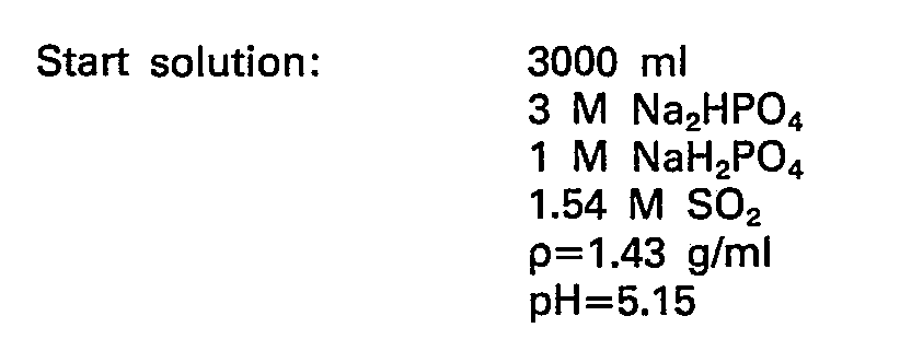
- The S02 concentration in the buffer solution was determined iodometrically. The amount of H20+S02 evaporated was determined by weighing. The density of the solution was determined by weighing known volumes. After the evaporation was stopped, the crystals formed in the vessel were first dissolved by adding water and then the solution was diluted to the start volume, before the S02 content, the density and the pH were measured. The following results were obtained.
-


-

- Comparative example


- Mass balances:

-

- Part of this loss can be explained by SO2 escaping as gas when the vessel was opened after the evaporation.

- The results of the batch evaporation experiments allow the following conclusions, referring to the conditions of the experiments:
- ―The energy (steam) consumption for driving off S02 from clear solutions of phosphate buffer is about 1/3 the consumption for clear sulphite solutions. This is surprising, since from the S02 gas-liquid equilibrium data at hand referring to 55°C, one would rather expect the phosphate buffer to require distinctly more energy than the sulphite buffer (Figure 2).
- -When the crystallization starts the steam consumption drops for both buffers.
- - Evaporation with crystallization is problematic with the sulphite buffer because of its tendency to form deposit on the heating element. This problem was not seen with the phosphate buffer.
- An S02 containing buffer solution was by means of a metering pump conveyed to a 500 ml glass flask serving as a boiler and heated from the outside for evaporating a S02-steam mixture at atmospheric pressure, with simultaneous crystallization of the basic buffer component Na2HP04. The experiments were carried out semicontinuously by allowing the crystals with mother liquor to accumulate in the boiler. The vapour was first passed through a condenser for condensation of steam and then together with the condensate down into an aqueous H202 solution, in which all SO2 was odizied to sulphuric acid which was then determined quantitatively by titration with standard NaOH. The evaporation procedure was followed by very quickly replacing the H202 bottle every 30 minutes.
- Before starting the pump the boiler was charged with a S02-free buffer which was subjected to evaporation. The experiments were stopped when the stirrer could not function properly because of too much and too thick slurry.
- The S02 concentrations in the liquid feed were determined iodometrically, and the total liquid volume charged was determined by weighing and container with feed liquid before and after the experiment and by density measurements.
- The S02 content in the slurry remaining in the boiler after the experiment had been terminated, was determined iodometrically after addition of water and dissolution of the crystal mass to a known volume.
- The supply from the pump was controlled with a rotameter calibrated with pure water. Due to deviations in specific density and viscosity between water and the buffer solutions the stated supply rates should only be taken as indications.
-

- To the start solution 20 ml of water was added, and the resulting solution was evaporated until crystals started to form. Then 15 g of Na2HP04. 2H20 crystals were added, and the pump was started.


- Material balance:
- Total feed of SO2 buffer: 1.151 I
- Total amount of SO2 in feed: 1.151 · 1.50 · 64.1=110.67 g
- Total amount of S02 evaporated (Samples 1-9): 86.74 g
- Calculated amount of S02 remaining in evaporator: 23.76 g
- Amount of S02 remaining in evaporator found by analysis (residue): 25.3 g
- (The discrepancy is within a reasonable error of analysis).
- Residue of SO2 found as equivalent concentration in the feed liquid="regenerated" buffer solution: 25.3/1.151 · 64.1=0.34 M
- Corresponding pH according to Figure 1 at 55°C: about 6.35
- The steam consumption S=8-9 tons per ton of S02 may with double effect evaporation presumably be reduced to S=5-6 tons per ton S02. This compares with the 7-8 tons per ton SO2 referred to above for the sulphite process.
- Interpolation of the gas-liquid-equilibrium data in Figure 2 gives the following S02 partial pressures at equilibrium, p*SO2:

- The absorption unit will often be operated at about 55°C. From these equilibrium pressures it may be concluded that 1.50 M S02 in the buffer solution may be obtained with relatively low partial pressures of S02 of the feed gas, and that even with as much as 0.34 M S02 in the feed solution to the absorber, it may be possible to obtain a surprisingly complete SO2 absorption.
- The remaining content of S02 in the liquid after the evaporation can presumably be brought down to a considerably lower value than the value of 0.34 M found herein, when a regular continuous crystallizer is used. This will make it possible to obtain an even more complete absorption.
- Comparative Example.

- 74.02 g of H20 was evaporated, and the feed pump was started before any crystals had precipitated.


- At the end of the suspension was extraordinary viscous and had a total volume of about 0.5 I. The crystals were dissolved by addition of water to a volume of 2 I. pH measured in the resulting solution=6.45 (55°C).
- Further data for the experiment were as follows:
- Evaporated S02 according to samples 1-9: 66.76 g=1.04 moles
- Total weight of feed: 1730 g
- Volume of feed: 1.730/1.21=1.430 I
- S02 added with feed: 1.43 · 1.25=1.79 moles
- Na2SO3 added with feed: 1.43 · 1.70=2.43 moles
- Na2S03 in the start solution: 1.33 · 0.25=0.33 moles
- SO2+Na2SO3+NaHSO3 in evaporator at the termination: 3.43 moles
- S02 remaining in evaporator as equivalent concentration in regenerated buffer:

- Calculated from S-containing material added (S02 and Na2S03):

- Calculated on the basis of evaporated S02 and residue of S-containing material in the evaporator;

- The discrepancy is within reasonable analysis error.
- The high values for the initial specific steam consumption is due to the high pH in the start solution. Presumably close to stable conditions with S=11-12 g/g were not attained until sample No. 7.
- The pH values of the start and regenerated solutions are in good conformity with the information given above for commercial plants. This also applies to the concentrations of Na2SO3 and SO2.
- Interpolation of the gas-liquid equilibrium data for S02 at 55°C in Figure 2 gives the following S02 equilibrium partial pressures, p*so2:
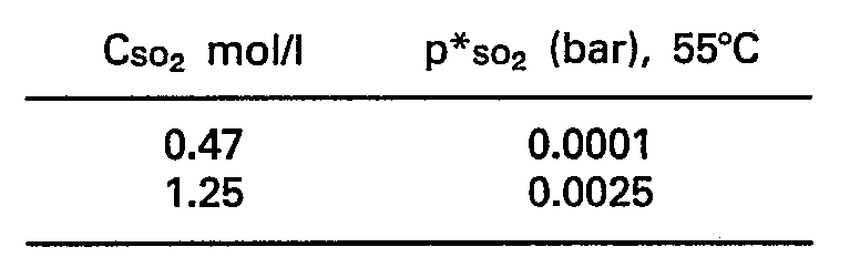
- The absorption unit will often operate at about 55°C. From these data it is then derived that 1.25 M SO2 in the loaded buffer requires a rather high SO2 partial pressure in the feed gas. Also the partial pressure of 0.0001 bar in the regenerated buffer is well above the German norm for clean-up of 0.00014 bar for large boilers.
- The results show substantially lower S-values for the phosphate than for the sulphite buffer, 8-9 compared to 11-12 tons of steam/ton of S02. This is in contradiction to the higher S02 partial pressures of the sulphite buffer at 55°C. Thus, these experiments indicate that SO2 is surprisingly easier to liberate from the phosphate buffer than from the sulphite buffer upon boiling at atmospheric pressure.
- At 55°C the S02 partial pressure in the regenerated phosphate buffer is only about 1/3 of the partial pressure of S02 in regenerated sulphite buffer. This would make the phosphate system better suited than the sulphite system when extremely low residual content of SO2 in the purified gas is required.
- A gas-circulation circuit illustrated in Figure 3 comprised a gas-scrubbing bottle A, a teflon membrane pump B, a gas absorption bottle C, and a glass tube D. The circulation circuit was connected to an oxygen-filled gas cylinder E, through a reduction valve F, for constant supply pressure. Before the experiment the circulation circuit was filled with oxygen, and the gas scrubbing bottle A was charged with a known volume of buffer solution charged with S02.
- By adjusting the three way valves H the gas flow could be directed through alternatively (a) the tube D and the gas scrubbing bottle A or (b) the tube D and the absorption bottle C.
- The oxidation experiment was started by starting the pump B to circulate the oxygen gas through the buffer in bottle A.
- The experiment was stopped by stopping the pump. The S02 content of the absorption bottle A was determined iodometrically before and after the experiment. The S02 content in the gas phase in the gas circulation circuit of known volume, was determined after the experiment by standard base titration after absorption in an aqueous H202 solution in the bottle C. The whole apparatus was kept at a constant temperature.
- 100 ml of buffer solution was used for each experiment. All experiments were carried out at 60°C and 1 atm. total pressure.
- The oxidation losses were calculated from the following formula:

- n°start=total no. of moles of SIV-compounds (Na2S03, NaHS03 and S02) in buffer at start
- n°end=do. after oxidation
- ngas=no. of moles of SO2 present in the gas volume after oxidation
- nso2, start=no. of moles of S02 a ed to buffer before start.
- The following results were obtained:

- The buffer composition at the start was:
- Phosphate buffer
- 3.00M Na2HPO4+1.00M NaH2P04+0.50M Na2S04+1.50M S02 pH=5.20 Sulphite buffer
- 1.70M Na2S03+0.50M Na2S04+1.22M S02 pH=5.30
- The oxidation in the sulphite system is seen to be very substantial, whereas the oxidation in the phosphate system is so small that it is considered to be insignificant. This is supported by the following observations:
- By closing the valve F during the oxidation experiment the oxygen uptake by the buffer in bottle A due to oxidation could be followed visually by observing the movement of the liquid level in the manometer G. For the sulphite system the level moved rather rapidly. For the phosphate system there was no observable change of the level even after 5 min. This indicates that only the sulphite system exhibited significant oxidation.
- Literature:
- (1) Erga, O.
- S02 recovery by sodium citrate solution scrubbing Chem. Eng. Sci. 35 162-169 (1980)
- (2). Nato CCMS Study.
- Phase 1.2. Status report on the sodium sulfite scrubbing flue gas desulfurization process. March 1978.
- Pedco Environmental, Cincinati, Ohio.
- Contract No. 68-01-4147.
- (3) Eldring, A. K.
- The Stauffer S02 abatement system.
- In: I. Chem. E. (London) Symposium No. 57
- "The Control of Sulphur and other Gaseous Emissions", Salford, April 1979, p J1-J20.
Claims (9)
Priority Applications (1)
| Application Number | Priority Date | Filing Date | Title |
|---|---|---|---|
| AT86905446T ATE40652T1 (en) | 1985-09-16 | 1986-09-16 | PROCESS FOR RECOVERING SULFUR DIOXIDE FROM GASES. |
Applications Claiming Priority (2)
| Application Number | Priority Date | Filing Date | Title |
|---|---|---|---|
| NO853622 | 1985-09-16 | ||
| NO853622 | 1985-09-16 |
Publications (2)
| Publication Number | Publication Date |
|---|---|
| EP0235243A1 EP0235243A1 (en) | 1987-09-09 |
| EP0235243B1 true EP0235243B1 (en) | 1989-02-08 |
Family
ID=19888479
Family Applications (1)
| Application Number | Title | Priority Date | Filing Date |
|---|---|---|---|
| EP86905446A Expired EP0235243B1 (en) | 1985-09-16 | 1986-09-16 | Process for the recovery of sulphur dioxide from gas flows |
Country Status (8)
| Country | Link |
|---|---|
| US (1) | US4948572A (en) |
| EP (1) | EP0235243B1 (en) |
| AT (1) | ATE40652T1 (en) |
| AU (1) | AU6371386A (en) |
| DD (1) | DD252978A5 (en) |
| DE (1) | DE3662027D1 (en) |
| PL (1) | PL261412A1 (en) |
| WO (1) | WO1987001612A1 (en) |
Families Citing this family (7)
| Publication number | Priority date | Publication date | Assignee | Title |
|---|---|---|---|---|
| NO164218C (en) * | 1988-02-24 | 1990-09-12 | Sintef | PROCEDURE FOR CLEANING AFFICIENT BUFFER SOLUTIONS. |
| US5785888A (en) * | 1995-03-24 | 1998-07-28 | Milmac Operating Company | Method for removal of sulfur dioxide |
| US5851265A (en) * | 1996-09-03 | 1998-12-22 | Monsanto Company | Selective removal and recovery of sulfur dioxide from effluent gases using organic phosphorous solvents |
| NO312131B1 (en) * | 2000-03-06 | 2002-03-25 | Olav Erga | Process for removing sodium sulfate from a phosphate solution |
| US9205150B2 (en) | 2011-12-05 | 2015-12-08 | Incept, Llc | Medical organogel processes and compositions |
| EP2844369B1 (en) | 2012-05-02 | 2020-09-02 | MECS, Inc. | Regenerative recovery of contaminants from effluent gases |
| CA2902732C (en) | 2013-03-15 | 2021-10-26 | Ernesto Vera-Castaneda | Regenerative recovery of contaminants from effluent gases |
Family Cites Families (8)
| Publication number | Priority date | Publication date | Assignee | Title |
|---|---|---|---|---|
| US2031802A (en) * | 1932-05-06 | 1936-02-25 | Ici Ltd | Recovery of sulphur dioxide from gas mixtures |
| GB419068A (en) * | 1933-05-03 | 1934-11-05 | Arthur Maurice Clark | Improvements in or relating to the recovery of sulphur dioxide from gas mixtures |
| US2142987A (en) * | 1935-12-24 | 1939-01-10 | Bacon | Recovery of sulphur dioxide from gases |
| US3633339A (en) * | 1968-11-18 | 1972-01-11 | Freeport Minerals Co | Recovery of sulfur dioxide from a sulfur dioxide-containing aqueous ammonium phosphate solution |
| US3911093A (en) * | 1971-10-18 | 1975-10-07 | Stauffer Chemical Co | Recovery of SO{HD 2 {B from waste gas emissions |
| US3969492A (en) * | 1973-10-29 | 1976-07-13 | U.S. Filter Corporation | Recovery of elemental sulfur from sulfur dioxide bearing waste gases |
| SE405109B (en) * | 1977-04-12 | 1978-11-20 | Svenska Flaektfabriken Ab | PROCEDURE FOR EXTRACTING CONCENTRATED SULFUR DIOXIDE FROM EXHAUST SULFUR DIOXIDE |
| US4519994A (en) * | 1984-02-27 | 1985-05-28 | Stauffer Chemical Company | Process for absorption of SO2 into phosphate absorbent |
-
1986
- 1986-09-15 DD DD86294405A patent/DD252978A5/en not_active IP Right Cessation
- 1986-09-16 AT AT86905446T patent/ATE40652T1/en not_active IP Right Cessation
- 1986-09-16 AU AU63713/86A patent/AU6371386A/en not_active Abandoned
- 1986-09-16 EP EP86905446A patent/EP0235243B1/en not_active Expired
- 1986-09-16 PL PL1986261412A patent/PL261412A1/en unknown
- 1986-09-16 DE DE8686905446T patent/DE3662027D1/en not_active Expired
- 1986-09-16 WO PCT/NO1986/000064 patent/WO1987001612A1/en not_active Ceased
-
1989
- 1989-01-31 US US07/305,105 patent/US4948572A/en not_active Expired - Lifetime
Also Published As
| Publication number | Publication date |
|---|---|
| DE3662027D1 (en) | 1989-03-16 |
| WO1987001612A1 (en) | 1987-03-26 |
| AU6371386A (en) | 1987-04-07 |
| EP0235243A1 (en) | 1987-09-09 |
| US4948572A (en) | 1990-08-14 |
| PL261412A1 (en) | 1987-09-07 |
| DD252978A5 (en) | 1988-01-06 |
| ATE40652T1 (en) | 1989-02-15 |
Similar Documents
| Publication | Publication Date | Title |
|---|---|---|
| US6544492B1 (en) | Regeneration method for process which removes hydrogen sulfide from gas streams | |
| US3790660A (en) | Process for recovering sulfur dioxide from gases | |
| US3911093A (en) | Recovery of SO{HD 2 {B from waste gas emissions | |
| US2729543A (en) | Removal of sulfur dioxide from gases containing the same | |
| WO1987001612A1 (en) | Process for the recovery of sulphur dioxide from gas flows | |
| KR100286384B1 (en) | Method and apparatus for absorbing hydrogen sulfide | |
| US6896863B2 (en) | Sodium cyanide process | |
| US3995015A (en) | Process for making sodium metabisulfite | |
| US4634582A (en) | Sulfur dioxide removal process | |
| CA1150036A (en) | Flue gas desulfurization process | |
| EP1334069B1 (en) | System and method for precipitating salts | |
| US4387037A (en) | Removal of sulfur from waste gas streams | |
| US5250280A (en) | Method of preparing storage-stable aqueous sodium peroxymonsulfate solutions | |
| EP0395740B1 (en) | Process for purifying aqueous buffer solutions | |
| US3886069A (en) | Process for purification of aqueous sodium citrate solutions | |
| US4256713A (en) | Flue gas treatment with intermittent addition of alkaline reagent to scrubbing liquor | |
| JP7738434B2 (en) | Sodium carbonate manufacturing method | |
| US4310691A (en) | Method for selectively recovering sodium citrate from an aqueous solution | |
| US4003985A (en) | Production of sodium sulfite | |
| US4162299A (en) | Process for the removal of sulfur oxides | |
| US4411875A (en) | Dual alkali process for combustion gas cleaning | |
| US4216189A (en) | Sulfur dioxide removal process | |
| US20030106852A1 (en) | Process for purifying aqueous buffer solutions | |
| US4363791A (en) | Alkanolaminium carboxylate solvents for selective SO2 absorption | |
| EP0139449B1 (en) | Process for purifying gases containing sulphur dioxide |
Legal Events
| Date | Code | Title | Description |
|---|---|---|---|
| PUAI | Public reference made under article 153(3) epc to a published international application that has entered the european phase |
Free format text: ORIGINAL CODE: 0009012 |
|
| AK | Designated contracting states |
Kind code of ref document: A1 Designated state(s): AT BE CH DE FR GB IT LI LU NL SE |
|
| 17P | Request for examination filed |
Effective date: 19870922 |
|
| 17Q | First examination report despatched |
Effective date: 19880721 |
|
| GRAA | (expected) grant |
Free format text: ORIGINAL CODE: 0009210 |
|
| AK | Designated contracting states |
Kind code of ref document: B1 Designated state(s): AT BE CH DE FR GB IT LI LU NL SE |
|
| PG25 | Lapsed in a contracting state [announced via postgrant information from national office to epo] |
Ref country code: IT Free format text: LAPSE BECAUSE OF FAILURE TO SUBMIT A TRANSLATION OF THE DESCRIPTION OR TO PAY THE FEE WITHIN THE PRESCRIBED TIME-LIMIT;WARNING: LAPSES OF ITALIAN PATENTS WITH EFFECTIVE DATE BEFORE 2007 MAY HAVE OCCURRED AT ANY TIME BEFORE 2007. THE CORRECT EFFECTIVE DATE MAY BE DIFFERENT FROM THE ONE RECORDED. Effective date: 19890208 Ref country code: SE Effective date: 19890208 Ref country code: LI Effective date: 19890208 Ref country code: AT Effective date: 19890208 Ref country code: CH Effective date: 19890208 Ref country code: BE Effective date: 19890208 Ref country code: FR Free format text: THE PATENT HAS BEEN ANNULLED BY A DECISION OF A NATIONAL AUTHORITY Effective date: 19890208 Ref country code: NL Effective date: 19890208 |
|
| REF | Corresponds to: |
Ref document number: 40652 Country of ref document: AT Date of ref document: 19890215 Kind code of ref document: T |
|
| REF | Corresponds to: |
Ref document number: 3662027 Country of ref document: DE Date of ref document: 19890316 |
|
| REG | Reference to a national code |
Ref country code: CH Ref legal event code: PL |
|
| EN | Fr: translation not filed | ||
| NLV1 | Nl: lapsed or annulled due to failure to fulfill the requirements of art. 29p and 29m of the patents act | ||
| PG25 | Lapsed in a contracting state [announced via postgrant information from national office to epo] |
Ref country code: LU Free format text: LAPSE BECAUSE OF NON-PAYMENT OF DUE FEES Effective date: 19890930 |
|
| PLBE | No opposition filed within time limit |
Free format text: ORIGINAL CODE: 0009261 |
|
| STAA | Information on the status of an ep patent application or granted ep patent |
Free format text: STATUS: NO OPPOSITION FILED WITHIN TIME LIMIT |
|
| 26N | No opposition filed | ||
| REG | Reference to a national code |
Ref country code: GB Ref legal event code: IF02 |
|
| PGFP | Annual fee paid to national office [announced via postgrant information from national office to epo] |
Ref country code: GB Payment date: 20050908 Year of fee payment: 20 |
|
| PGFP | Annual fee paid to national office [announced via postgrant information from national office to epo] |
Ref country code: DE Payment date: 20050927 Year of fee payment: 20 |
|
| PG25 | Lapsed in a contracting state [announced via postgrant information from national office to epo] |
Ref country code: GB Free format text: LAPSE BECAUSE OF EXPIRATION OF PROTECTION Effective date: 20060915 |
|
| REG | Reference to a national code |
Ref country code: GB Ref legal event code: PE20 |