EP0232839B1 - Improved transit for cables and pipes - Google Patents
Improved transit for cables and pipes Download PDFInfo
- Publication number
- EP0232839B1 EP0232839B1 EP87101464A EP87101464A EP0232839B1 EP 0232839 B1 EP0232839 B1 EP 0232839B1 EP 87101464 A EP87101464 A EP 87101464A EP 87101464 A EP87101464 A EP 87101464A EP 0232839 B1 EP0232839 B1 EP 0232839B1
- Authority
- EP
- European Patent Office
- Prior art keywords
- blocks
- packer
- frame
- plate
- cables
- Prior art date
- Legal status (The legal status is an assumption and is not a legal conclusion. Google has not performed a legal analysis and makes no representation as to the accuracy of the status listed.)
- Expired - Lifetime
Links
- 230000006835 compression Effects 0.000 claims abstract description 68
- 238000007906 compression Methods 0.000 claims abstract description 68
- 238000003780 insertion Methods 0.000 claims abstract description 14
- 230000037431 insertion Effects 0.000 claims abstract description 14
- 230000000694 effects Effects 0.000 claims abstract description 8
- 230000000295 complement effect Effects 0.000 claims description 10
- 238000006073 displacement reaction Methods 0.000 claims description 6
- 239000002184 metal Substances 0.000 claims description 3
- 239000012858 resilient material Substances 0.000 claims description 3
- 238000007789 sealing Methods 0.000 abstract description 5
- 238000009434 installation Methods 0.000 description 7
- 238000011065 in-situ storage Methods 0.000 description 4
- 238000012856 packing Methods 0.000 description 4
- 239000007787 solid Substances 0.000 description 4
- 238000005192 partition Methods 0.000 description 3
- 230000014759 maintenance of location Effects 0.000 description 2
- 239000000463 material Substances 0.000 description 2
- XLYOFNOQVPJJNP-UHFFFAOYSA-N water Substances O XLYOFNOQVPJJNP-UHFFFAOYSA-N 0.000 description 2
- 241000283984 Rodentia Species 0.000 description 1
- 230000032683 aging Effects 0.000 description 1
- 230000000712 assembly Effects 0.000 description 1
- 238000000429 assembly Methods 0.000 description 1
- 230000004888 barrier function Effects 0.000 description 1
- 230000033228 biological regulation Effects 0.000 description 1
- 238000010276 construction Methods 0.000 description 1
- 230000005611 electricity Effects 0.000 description 1
- 230000007613 environmental effect Effects 0.000 description 1
- 230000009970 fire resistant effect Effects 0.000 description 1
- 231100001261 hazardous Toxicity 0.000 description 1
- 125000006850 spacer group Chemical group 0.000 description 1
- 239000011800 void material Substances 0.000 description 1
Images


Classifications
-
- F—MECHANICAL ENGINEERING; LIGHTING; HEATING; WEAPONS; BLASTING
- F16—ENGINEERING ELEMENTS AND UNITS; GENERAL MEASURES FOR PRODUCING AND MAINTAINING EFFECTIVE FUNCTIONING OF MACHINES OR INSTALLATIONS; THERMAL INSULATION IN GENERAL
- F16L—PIPES; JOINTS OR FITTINGS FOR PIPES; SUPPORTS FOR PIPES, CABLES OR PROTECTIVE TUBING; MEANS FOR THERMAL INSULATION IN GENERAL
- F16L5/00—Devices for use where pipes, cables or protective tubing pass through walls or partitions
- F16L5/02—Sealing
- F16L5/08—Sealing by means of axial screws compressing a ring or sleeve
-
- F—MECHANICAL ENGINEERING; LIGHTING; HEATING; WEAPONS; BLASTING
- F16—ENGINEERING ELEMENTS AND UNITS; GENERAL MEASURES FOR PRODUCING AND MAINTAINING EFFECTIVE FUNCTIONING OF MACHINES OR INSTALLATIONS; THERMAL INSULATION IN GENERAL
- F16L—PIPES; JOINTS OR FITTINGS FOR PIPES; SUPPORTS FOR PIPES, CABLES OR PROTECTIVE TUBING; MEANS FOR THERMAL INSULATION IN GENERAL
- F16L5/00—Devices for use where pipes, cables or protective tubing pass through walls or partitions
- F16L5/02—Sealing
- F16L5/14—Sealing for double-walled or multi-channel pipes
-
- H—ELECTRICITY
- H02—GENERATION; CONVERSION OR DISTRIBUTION OF ELECTRIC POWER
- H02G—INSTALLATION OF ELECTRIC CABLES OR LINES, OR OF COMBINED OPTICAL AND ELECTRIC CABLES OR LINES
- H02G3/00—Installations of electric cables or lines or protective tubing therefor in or on buildings, equivalent structures or vehicles
- H02G3/22—Installations of cables or lines through walls, floors or ceilings, e.g. into buildings
Definitions
- This invention relates to a transit providing a lead-through for electric cables or pipes that are required to extend through an opening in a wall, bulkhead, partition or the like.
- This invention concerns certain improvements in a particular kind of transit as hereinafter defined and which is for use with cables, wires, pipes or tubes or the like elongate elements commonly used in an installation for conducting electricity, service commodities such as gas, oil or water, or enclosing such service lines
- service commodities such as gas, oil or water, or enclosing such service lines
- the term "cable" is used and should be interpreted in the context to include all such aforesaid elongate elements.
- This invention is particularly concerned with a transit of the kind now defined as comprising a rectangular metal frame defining an opening through which the cables are to extend, a series of sets of modular blocks for assembly in rows within the frame opening, the blocks being adapted for surrounding each cable or for blanking off a modular space, and a compression and packer assembly for mounting in the frame opening to clamp the assembled blocks together and around each cable with the compression and packer assembly completing filling of the frame opening.
- transits of the defined kind are used in a wide range of applications and are installed in various environments including hazardous and have to meet specific regulations for fire-proof or flame-proof or gas-tight installations.
- a transit has to be assembled on site and often the working conditions at the installation site are difficult in many respects, such as:- access and location; the numbers, types and sizes of cable; limited working space and lack of access to both inlet and exit sides of the lead-through; and, ambient temperature, weather and environmental conditions.
- each block in each series set of the modular blocks, is of square section and has a length substantially the same as the depth of the metal frame into which the blocks are assembled in an array of superimposed rows.
- Each block in a set of blocks has the same external dimensions and a plurality of blocks from one set will completely fill one row across the inside of the frame.
- each set includes solid blank blocks for assembly in the row.
- the blocks For a cable lead-through, the blocks have a through hole of a diameter corresponding to the diameter of the cable to be surrounded by the block, and to facilitate fitting and assembly each such block is formed in two complementary halves with semi-cylindrical recesses that, when aligned, provide the lead-through hole in which the cable is seated.
- This invention as later described may be applied to transits for use with such modular blocks as just mentioned or with other forms of modular blocks used for the same purpose of providing the lead-throughs for the cables or pipes and blanking blocks for filling the modular space where no lead-through is required.
- This invention is particularly concerned with the compression and packer assembly of a transit of the defined kind.
- the compression and packer assembly is arranged to be received within the frame to fill the remaining space left after the rows of modular blocks defining the lead-throughs and blanks have been assembled.
- the compression and packer assembly has to apply pressure to the assembled array of modular blocks and cables to clamp these together and around the cables whilst also completely filling the frame.
- the compression and packer assembly relies on the resilient deformation of a packer block or blocks which are inserted in the frame to fill the remainder of the opening after the modular blocks and cable have been assembled. Due to the inherent properties of the assembled modular blocks and cables, before the packer can be inserted, the assembled array has to be forced down into the frame to provide a clearance opening into which the packer can be inserted. Commonly, this initial compression is achieved by using a pressure plate which seats on the final row of modular blocks and a load is applied to the plate by a bolt which is mounted in an end wall of the frame and which can be unscrewed to engage the pressure plate and then on further unscrewing gradually applies the load to the assembled array of modular blocks to force them together around the cables.
- a packer block corresponding to the internal width of the frame and designed to seat on the plate engaging the inner faces of the side walls of the frame has to be inserted into the clearance space with the packer having a cut-out or suitable recess for the bolt which has to be left in situ maintaining the compression on the assembled array of blocks and cables whilst the packer block is so inserted.
- the packer block is then expanded by a squeezing action applied between front and rear faces of the packer block by a clamping arrangement, and then the forces applied to the assembly enclosed within the frame are distributed with all of the parts and the cables being subject to compression loads to maintain the desired clamping and sealing engagement.
- the bolt is left in situ although it is usually no longer needed to apply any compression to the array of blocks and cables as the pressure is now applied through the expanded packer block engaging the pressure plate.
- the cut-out or recess in the packer block may be filled by a packer piece which is either fitted onto the bolt initially or which is finally inserted when the last adjustment of the bolt is completed.
- EP-A-0,154,027 and EP-A-0183,300 disclose transits in which an array of modular blocks and cables assembled in a rectangular frame is compressed by applying a load to a pressure plate by means of a screw bolt acting in a direction normal to the cable axes between the plate and an end wall of the frame.
- the present invention provides a solution to the problems of the prior art transits in which the bolt remains within the frame opening in the assembled transit and packer blocks are fitted around the bolt by providing at least one packer block that is inserted into the clearance space beside the compression bolt when engaged with the plate to partially fill the clearance space, and at least one packer block that is inserted into the clearance space after the compression bolt has been displaced from engagement with the plate clear of the frame opening such that the packer blocks are seated beside each other between the side walls of the frame and completely fill the clearance space.
- the compression bolt engages the pressure plate to allow insertion of at least one packer block into the clearance space beside the bolt and the bolt is then displaced from engagement with the plate clear of the frame opening to allow insertion of at least one further packer block such that the packer blocks completely fill the clearance space.
- the bolt does not extend into the clearance space and no special steps are required to accommodate the bolt in the frame opening in the assembled transit.
- the compression and packer assembly includes a distance member which is interposed between the end wall of the frame and the plate to limit the reactive effect of the assembled modular blocks and cables on the plate on displacement of the bolt away from the plate following the insertion of at least one packer block.
- the pressure plate can be maintained in substantially the correct position holding the modular blocks and cables in the desired position whilst the remaining packer blocks are inserted.
- the distance member may comprise a pin or other rigid member located on or in a packer block and extending in said first direction.
- the distance member comprises a pin located within a bore formed in a packer block.
- At least one of the outer packer blocks is inserted into the clearance space between the plate and the end wall of the frame with the bolt holding the plate in position.
- the other outer packer block can then be inserted with the compression bolt being then displaced with the plate being held in position by the outer packer blocks and any distance members.
- the central block may then be inserted without interference from the bolt.
- only one outer packer block can be inserted first, then the compression bolt displaced whilst a distance member holds the plate in position, and then the central or the other outer packer block may be inserted.
- the packer blocks may have complementary taper faces for abutting engagement with each other on insertion of each packer block into position within the clearance space between the end wall of the frame and the plate.
- the taper faces may be inclined either to said first direction and/or inclined to said second direction, and these taper faces may be arranged to provide a wedge-like effect between the packer blocks.
- the provision of the taper faces on the packing blocks can aid assembly of the separate blocks and also improves the distribution of compression forces applied to the packer blocks by the compressor studs.
- the compressor studs may extend through opposed support plates engaging end faces of each packer block. These support plates may be common to all of the packer blocks and extend across the frame opening with an outer clearance. One support plate may be rigidly connected to the frame. Each packer block may have a separate support plate either at one end face or at both end faces.
- the plate has a planar flat underside for engagement with the row of modular blocks as last assembled, but the opposed side of the plate may be curved in the manner of a bridge extending between the side walls of the frame with the packer blocks having complementary underside faces to engage the plate.
- both the plate and the underside faces of the packer blocks may be complementary and may be profiled or have inclined or tapered portions to both assist in distributing the compressive forces and other loads as well as assisting correct alignment and fitting of the parts together.
- This compression and packer assembly may comprise only two packer blocks, and these can be of different widths so that one smaller packer block is inserted in the access clearance space beside the compression bolt, and thereafter a large packer block can be inserted to fill and close the clearance space following displacement of the compression bolt.
- This compression and packer assembly may comprise more than three packer blocks, and the number of packer blocks employed may designed to suit the shape and configuration and dimensions of the transit frame.
- the compression bolt is mounted in the central portion of the end wall of the frame, but this is not essential provided that the bolt can be displaced to apply the desired initial pressure to the plate to hold the assembled array of modular blocks and cables in position whilst the packer block or blocks are inserted.
- the improved cable transit comprises a rectangular frame 1 defining an opening 2 through which cables 3 of different sizes extend.
- each cable 3 is held within a lead-through block 4 whilst solid blank blocks 5 fill the modular spaces of the opening where no cable is present.
- Each lead-through block 4 comprises two complementary half-blocks 40 which have semi-cylindrical recesses that define a passageway or lead-through for the cable 3.
- the frame is for mounting or support in an aperture in a bulkhead or partition or the like (not shown) and the numbers and sizes of cables may vary from one installation to another. For simplicity of explanation of this invention, only a small number of cables are depicted and the assembly is not as complex as found in practice where tens of cables may have to be accommodated and installed at the site location.
- each series set has a common length corresponding substantially to the depth of the opening 2 and the frame 1.
- Each series set has blocks of substantially square section with the respective width and height dimensions of each set being selected to a common multiple so that a plurality of blocks of each set will complete a row or fill a modular space within the frame.
- Typical suitable modular dimensions are 90mm, 60mm and 30mm for the square section blocks.
- Each set of modular blocks is assembled in a row and to separate and support the assembled rows, stay plates 6 extend therebetween to locate on the marginal edges of the side walls of the frame 1.
- the opening 2 is closed by a compression and packer assembly 7 which is for clamping and holding the rows of modular blocks in place and applies pressure to the modular blocks to seal these both to the cables 3, to each other, to the inner faces of the frame 1 and to the stay plates 6.
- the compression and packer assembly 7 comprises a pressure plate 8, three packer blocks 9,10 and 11 each having a respective compressor stud 12,13 and 14 extending therethrough.
- Each packer block 9,10 and 11 has a respective rear support plate 15,16 and 17 against which the rear head of each respective stud 12,13 and 14 engages.
- Each stud 12,13 and 14 extends through the respective block and through aligned openings in a front support plate 18 with respective nuts 19,20 and 21 being in threaded engagement with the free end of the associated stud projecting through the front support plate 18.
- the pressure plate 8 is a rigid body having a planar underside 22 for engagement with the upper faces of the top row of blocks 4 a and 5 a , and an edge flange 23 on each side of the plate 8 provides location ledges over-lying the upper marginal edges of the blocks as well as providing outer end lug portions that extend outwardly and engage the outer faces of the sides of the frame 1.
- the topside of the plate 8 has a flat central portion 24 and opposed inclined portions 25.
- Each of the packer blocks 9,10 and 11 are made of a resilient material and the outer blocks 9 and 11 have respective through holes 26,27 that extend transverse and spaced from the respective axes of the compression studs 12 and 14.
- a distance member in the form of a limit pin 28 is mounted in each through hole 26,27, and as shown in Figures 6 and 5, this pin 28 is arranged to engage the inner face of the upper end wall 29 of the frame 1 and the inclined portion of the pressure plate 8 so as to limit the degree of deformation of the blocks 9 and 11 when a reactive load is applied to the blocks in the direction of the axis of the limit pins as later explained.
- the upper end wall 29 of the frame 1 is provided with a central clearance hole 30.
- a hexagonal shaped boss 31 is rigidly mounted on the wall 29 and projects therefrom aligned with the clearance hole 30.
- the boss has an internal blind threaded bore 32 and a compression bolt 33 is in threaded engagement within the bore 32 with the head 34 of the bolt 33 being accessible through the clearance hole 30 for rotation by a suitable tool.
- the bolt 34 can be unthreaded to extend into the void below the boss 31 when the central packer block 10 is not fitted, and the head 34 of the bolt will engage with the central portion 24 of the plate 8.
- the packer blocks 9 and 11 are similar and have inner side faces that lie adjacent to the opposed side faces of the central packer block 10.
- the side faces of all the packer blocks 9,10 and 11 as shown in Figure 3 are parallel to each other and normal to their top or upper faces remote from the plate 8.
- the central packer block 10 has a flat underside face 35 engaging the flat central portion 24 of the plate 8.
- the underside faces of the packer blocks 9 and 11 are inclined relative to the upper or top faces and are complementary to the respective inclined portions 25 of the plate 8.
- the frame 1 is located in the structure with the runs of cables 3 extending through the opening 2 of the frame 1.
- the fitter is presumed to have the selection of modular lead-through blocks 4 for each cable and a number of blanking blocks 5.
- the largest lead-through blocks 4 c are used in the lower row, and firstly the lower half-blocks 40 c are set against the bottom inner wall of the frame 1 and the respective cables 3 are seated in the semi-cylindrical recesses in the half-blocks 40 c and the upper half-blocks 40 c are then seated on top to form the lead-through blocks 4 closing over the cables 3.
- the stay plate 6 is then inserted in place on top of this lower row of blocks with the marginal flanged edges of the stay plate 6 riding over the side edges of the frame 1 to locate the stay plate 6 in a similar manner as for the pressure plate 8.
- the stay plate has a central web portion which is pierced or of mesh to prevent high rates of heat transfer from one side to the other of the cable transit when installed.
- the fitter selects the next cables 3 to be located in the lead-through blocks 4 b for the next row and this row includes a solid blanking block 5 b .
- the assembly is as for the first row, and when the blocks 4 b and block 5 b are assembled another stay plate 6 is located over the row of blocks.
- the third row of blocks 4 a , and 5 a is then assembled in a similar manner, and all of the cable runs are enclosed by the selected lead-through blocks 4 and modular spaces are filled by the solid blocks 5a.
- the lower portion of the frame opening is filled by the rows of blocks and stay plates 6.
- the pressure plate 8 is located over the third row of blocks and seated over the assembled array of blocks and cables. Due to the resilient nature of the blocks and the effect of the cables, pressure must be applied to the assembled blocks to compress the blocks around the cables to seal the lead-through blocks both around the cable and to clamp them together and against the side walls of the frame 1 and to the stay plates 6.
- the compression bolt 33 is rotated to bring the head 34 into engagement with the flat central portion 24 of the plate 8 and on further rotation of the head 34 compressive forces are applied through the plate 8 to the assembled blocks.
- the fitter can insert an outer packer block 9 or 11 in the clearance space clear of the compression bolt which only extends to the centre of the clearance space and does not interfere with the fitting of either of the two side blocks 9 and 11.
- the compression bolt 33 can be counter-rotated to return the bolt into the bore of the boss 31 leaving the central area over the pressure plate 8 free for insertion of the central packer block 10 between the two side blocks 9 and 11.
- the assembly of the rows of blocks and cables will continue to exert reactive forces on the pressure plate 8 tending to displace it towards the top wall of the frame, and thus tending to compress the blocks 9 and 11.
- the limit pins 28 of defined length mounted in the packer blocks 9 and 11 restrict squeezing of the packer blocks because the opposed ends of the pins 28 will abut the rigid surfaces of the plate 8 and the end wall 29.
- the front support plate 18 can be engaged over the free ends of each of the compressor studs 12,13 and 14 and the respective nuts 19,20 and 21 placed in threaded engagement.
- the fitter then tightens each of the nuts 19,20 and 21 to apply compressive forces to the compression blocks so that the three blocks are brought into clamping engagement with each other and brought into engagement with the support plate 18.
- each of the packer blocks 9,10 and 11 is squeezed so as to cause resilient displacement of the block material in a direction transverse to the axis of each compressor stud thereby expanding the assembly both to fill the clearance opening between the pressure plate 8 and the frame 1 and to exert the required clamping pressure onto the assembly of blocks and cables beneath the pressure plate 8.
- the compression and packer assembly 7 completes the filling of the opening 2 in the frame 1 whilst also applying the necessary forces to the assembled rows of blocks and cables to ensure that the whole assembly is sealed together and securely located against displacement.
- the forces applied to the assembled rows of the lead-through and blank blocks are sufficient to ensure each lead-through block is in clamping and sealing engagement with the cable.
- the fitter can fit all of the parts together from the front of the frame where access to the rear of the frame is precluded as often happens when the frame is fitted in a closed bulkhead.
- the over-loading of the packing blocks by reactive forces applied by the natural resilience of the modular blocks and the cables is limited by the limit pins, and the limit pins do not interfere with the expansion of the packer blocks 9,11 when the compressor bolts are tightened.
- the outer blocks 9 and 11 each have inner side faces 9 a ,11 a that are not normal to the upper or top face of the respective blocks.
- the inner side faces 9 a ,11 a are inclined or tapered towards the rear support plates as well as being divergent from the upper or top faces so as to have a wedge-like inner form.
- Each side face 10 a of the central packer block has complementary inclined and taper faces which diverge towards the rear support plate 16.
- the assembly of the compression and packer component parts may proceed as just described for the arrangement depicted in Figure 3 if there is access to both sides of the transit frame. If the access is limited to the front, then the fitter would insert one of the side packer blocks 9 or 11 first, then insert the central packer block 10 and lastly insert the other side packer block which, with it's wedge-like shape is presented with it's smaller end to the space left for insertion and can be easily inserted and slid into place.
- each packer block has an independent support plate both at the rear and front.
- the front support plate comprises three separate plates respectively referenced as plate 118 for the outer packer blocks, and as plate 218 for the central packer block.
- the frame 1 has a support plate 50 rigidly secured to the side walls 51 and the end wall 29 so as to extend across the rear face of the upper portion of the frame 1.
- the support plate is provided with three through bores 52,53 and 54. These bores may have a square section so as to receive a respective square-shank of a compressor stud to locate the stud against relative rotation when a nut on the stud is screwed thereon.
- the packer blocks 9,10 and 11 as shown in Figure 7 are each formed with through bores of which one 10 c is shown in dashed lines, and each of the bores provide through passageways for the respective compressor studs of which the free ends are to project through aligned holes in the front support plate 18, and in the same manner as previously described, a nut would be mounted on the free end of each stud to compress the packer blocks to the desired degree when the assembly was completed.
- the studs could be rigidly fixed to project from the rear support plate, or the bores 52,53 and 54 could be internally threaded with the compressor studs being fully threaded along their shanks.
- the bores therethrough are threaded and the compressor studs are entered through the front of the packer blocks and any associated front support plate(s) overlying the packer blocks. All of these possibilities are capable of performance with the improved form of compression and packer assembly.
- the packer blocks as shown in Figure 7 include another important variation.
- the side blocks 9 and 11 have respective inner side faces 9 b and 11 b which are both tapering inwardly in the direction of the forward end shown nearest to the support plate 18, and in addition, these faces are inclined inwardly towards the central packer block 10 so that each side packer block is of wedge-like shape being smaller at the forward end.
- the central block 10 has complementary inclined side faces 10 b and the central block is thus of wedge-like shape with the smaller end of the wedge being inwards.
- each of the side packer blocks 9 and 11 can be fitted into the clearance space between the plate 8 whilst the compression bolt is engaged with the plate 8.
- the central packer block 10 can be presented with the smaller end first and slid into place with the compressor stud extending through the bore 10 c .
- distance members which are not limit pins disposed within bores or holes through a packer block.
- the support plates associated with at least one packer block could be sized and designed for abutment with the pressure plate and the frame so as to provide the necessary limit to compression of the packer block when the load applied by the compression bolt is relieved.
- separate short plates like spacers could be provided for interim temporary placement between the plate and inner wall of the frame.
- the fitting of the cable transit arises in various environments, and the cable transit may be installed as described in the vertical position, but it may be installed horizontally where safe retention and ease of assembly of the blocks and other component parts is required.
- the resilient material of which the lead-through and blanking blocks as well as the packer blocks are made can be of any suitable material which is flame-resistant, fire-resistant, water-resistant and resistant to effects of rodent attack, ageing, and temperature variations.
- cables As this is the commonest form of use of transits through bulkheads, partitions or the like.
- the invented cable transit can be used and applied to pipes or conduits and the term “cable” is not intended to be a limitation to the application and use of the invention nor is the use of the term “cable” to be interpreted as a limitation to the scope of this invention.
Landscapes
- Engineering & Computer Science (AREA)
- General Engineering & Computer Science (AREA)
- Architecture (AREA)
- Civil Engineering (AREA)
- Structural Engineering (AREA)
- Mechanical Engineering (AREA)
- Laying Of Electric Cables Or Lines Outside (AREA)
- Installation Of Indoor Wiring (AREA)
- Supports For Pipes And Cables (AREA)
Abstract
Description
- This invention relates to a transit providing a lead-through for electric cables or pipes that are required to extend through an opening in a wall, bulkhead, partition or the like. This invention concerns certain improvements in a particular kind of transit as hereinafter defined and which is for use with cables, wires, pipes or tubes or the like elongate elements commonly used in an installation for conducting electricity, service commodities such as gas, oil or water, or enclosing such service lines For convenience herein, the term "cable" is used and should be interpreted in the context to include all such aforesaid elongate elements.
- This invention is particularly concerned with a transit of the kind now defined as comprising a rectangular metal frame defining an opening through which the cables are to extend, a series of sets of modular blocks for assembly in rows within the frame opening, the blocks being adapted for surrounding each cable or for blanking off a modular space, and a compression and packer assembly for mounting in the frame opening to clamp the assembled blocks together and around each cable with the compression and packer assembly completing filling of the frame opening.
- Such defined kind of transit for cables is well known and is disclosed in Patent Specification GB 1,049,621.
- Typically, transits of the defined kind are used in a wide range of applications and are installed in various environments including hazardous and have to meet specific regulations for fire-proof or flame-proof or gas-tight installations. Usually, a transit has to be assembled on site and often the working conditions at the installation site are difficult in many respects, such as:- access and location; the numbers, types and sizes of cable; limited working space and lack of access to both inlet and exit sides of the lead-through; and, ambient temperature, weather and environmental conditions.
- Conventionally in transits of the defined kind, in each series set of the modular blocks, each block is of square section and has a length substantially the same as the depth of the metal frame into which the blocks are assembled in an array of superimposed rows. Each block in a set of blocks has the same external dimensions and a plurality of blocks from one set will completely fill one row across the inside of the frame. To provide blanks at locations in a row where no lead-through is required, each set includes solid blank blocks for assembly in the row. For a cable lead-through, the blocks have a through hole of a diameter corresponding to the diameter of the cable to be surrounded by the block, and to facilitate fitting and assembly each such block is formed in two complementary halves with semi-cylindrical recesses that, when aligned, provide the lead-through hole in which the cable is seated.
- This invention as later described may be applied to transits for use with such modular blocks as just mentioned or with other forms of modular blocks used for the same purpose of providing the lead-throughs for the cables or pipes and blanking blocks for filling the modular space where no lead-through is required.
- This invention is particularly concerned with the compression and packer assembly of a transit of the defined kind.
- As will be understood, the compression and packer assembly is arranged to be received within the frame to fill the remaining space left after the rows of modular blocks defining the lead-throughs and blanks have been assembled. The compression and packer assembly has to apply pressure to the assembled array of modular blocks and cables to clamp these together and around the cables whilst also completely filling the frame. It is important in practice that such compression and packer assembly be simple to install and in many applications it is essential that the correct pressure is applied to the assembled array either to avoid excessive clamping forces being applied to cables which must not be stressed or deformed, for instance optic cables, or to avoid insufficient clamping forces which could lead to failure in sealing required and or ineffectual retention of the arrayed modular blocks within the frame so that the transit assembly fails to provide a complete barrier in a wall, bulkhead or the like as intended.
- In the common known transits of the kind defined, the compression and packer assembly relies on the resilient deformation of a packer block or blocks which are inserted in the frame to fill the remainder of the opening after the modular blocks and cable have been assembled. Due to the inherent properties of the assembled modular blocks and cables, before the packer can be inserted, the assembled array has to be forced down into the frame to provide a clearance opening into which the packer can be inserted. Commonly, this initial compression is achieved by using a pressure plate which seats on the final row of modular blocks and a load is applied to the plate by a bolt which is mounted in an end wall of the frame and which can be unscrewed to engage the pressure plate and then on further unscrewing gradually applies the load to the assembled array of modular blocks to force them together around the cables.
- Once this stage has been completed, then a packer block corresponding to the internal width of the frame and designed to seat on the plate engaging the inner faces of the side walls of the frame has to be inserted into the clearance space with the packer having a cut-out or suitable recess for the bolt which has to be left in situ maintaining the compression on the assembled array of blocks and cables whilst the packer block is so inserted. The packer block is then expanded by a squeezing action applied between front and rear faces of the packer block by a clamping arrangement, and then the forces applied to the assembly enclosed within the frame are distributed with all of the parts and the cables being subject to compression loads to maintain the desired clamping and sealing engagement. The bolt is left in situ although it is usually no longer needed to apply any compression to the array of blocks and cables as the pressure is now applied through the expanded packer block engaging the pressure plate. The cut-out or recess in the packer block may be filled by a packer piece which is either fitted onto the bolt initially or which is finally inserted when the last adjustment of the bolt is completed.
- This arrangement leads to many complications on site as the main single packer block has to be entered into the clearance space from one side of the frame whilst manipulation of the bolt and any insertion of the packer piece is from the other side. In addition due to the effect of the assembled modular blocks and cables, often it is impossible to ensure that excessive and damaging pressure is not applied to the cables and modular blocks.
- To overcome such disadvantages, other proposals have been made and some implemented in use by providing a combined and adjustable compression and packer assembly which can be inserted into the clearance space when in a contracted condition, and then expanded in a direction within the plane of the frame and transverse to the axes of the cables so as to apply the desired pressure to clamp the assembled modular blocks, cables and packer together tightly within the frame opening. However, even with such adjustable compression and packer assembly difficulties in practical use arise due to the need to squeeze the packer assembly into the clearance space whilst attempting to hold the arrayed modular blocks and cables in situ, and in addition, problems also arise from the uncontrolled nature of the expansion of the compression and packer assembly and the forces generated within the frame during fitting.
- EP-A-0,154,027 and EP-A-0183,300 disclose transits in which an array of modular blocks and cables assembled in a rectangular frame is compressed by applying a load to a pressure plate by means of a screw bolt acting in a direction normal to the cable axes between the plate and an end wall of the frame.
- In both these prior art arrangements, the space around the bolt in the assembled transit is filled by packing pieces that are compressed by studs extending through the packing pieces in a direction normal to the bolt.
- It is an object of this invention to provide an improved transit of the kind defined for cables or pipes which has a particular form of compression and packer assembly which is both simple and easy to use in assembly of a transit as well as obviating known disadvantages with existing transits systems such as referred to previously.
- It is a further object of this invention to provide a compression and packer assembly which provides versatility for fitting and installation requirements.
- Other objectives and advantageous features of this invention will be referred to later herein with particular reference to exemplary embodiments of this invention.
- The present invention provides a solution to the problems of the prior art transits in which the bolt remains within the frame opening in the assembled transit and packer blocks are fitted around the bolt by providing at least one packer block that is inserted into the clearance space beside the compression bolt when engaged with the plate to partially fill the clearance space, and at least one packer block that is inserted into the clearance space after the compression bolt has been displaced from engagement with the plate clear of the frame opening such that the packer blocks are seated beside each other between the side walls of the frame and completely fill the clearance space.
- By this invention, the compression bolt engages the pressure plate to allow insertion of at least one packer block into the clearance space beside the bolt and the bolt is then displaced from engagement with the plate clear of the frame opening to allow insertion of at least one further packer block such that the packer blocks completely fill the clearance space. As a result, the bolt does not extend into the clearance space and no special steps are required to accommodate the bolt in the frame opening in the assembled transit.
- Preferably, the compression and packer assembly includes a distance member which is interposed between the end wall of the frame and the plate to limit the reactive effect of the assembled modular blocks and cables on the plate on displacement of the bolt away from the plate following the insertion of at least one packer block.
- By this distance member, the pressure plate can be maintained in substantially the correct position holding the modular blocks and cables in the desired position whilst the remaining packer blocks are inserted.
- The distance member may comprise a pin or other rigid member located on or in a packer block and extending in said first direction. Conveniently, the distance member comprises a pin located within a bore formed in a packer block.
- In the preferred form of compression and packer assembly of this invention, there are three such packer blocks. There is a central packer block and two outer or side packer blocks which are clear of the extent of the compression bolt when engaged with the plate.
- By this preferred arrangement, at least one of the outer packer blocks is inserted into the clearance space between the plate and the end wall of the frame with the bolt holding the plate in position. Depending on the arrangement and type of installation, the other outer packer block can then be inserted with the compression bolt being then displaced with the plate being held in position by the outer packer blocks and any distance members. The central block may then be inserted without interference from the bolt. In some arrangements, only one outer packer block can be inserted first, then the compression bolt displaced whilst a distance member holds the plate in position, and then the central or the other outer packer block may be inserted.
- The advantages and merits of this separate assembly of the packer blocks whilst maintaining the plate in controlled engagement with the array of modular blocks and cables will be appreciated as a considerable advance over the prior arrangements as previously discussed.
- The packer blocks may have complementary taper faces for abutting engagement with each other on insertion of each packer block into position within the clearance space between the end wall of the frame and the plate. The taper faces may be inclined either to said first direction and/or inclined to said second direction, and these taper faces may be arranged to provide a wedge-like effect between the packer blocks.
- The provision of the taper faces on the packing blocks can aid assembly of the separate blocks and also improves the distribution of compression forces applied to the packer blocks by the compressor studs.
- The compressor studs may extend through opposed support plates engaging end faces of each packer block. These support plates may be common to all of the packer blocks and extend across the frame opening with an outer clearance. One support plate may be rigidly connected to the frame. Each packer block may have a separate support plate either at one end face or at both end faces.
- Various features relating to the design and construction of the frame and parts of the transit associated with the compression and packer assembly will be described later herein.
- Preferably, the plate has a planar flat underside for engagement with the row of modular blocks as last assembled, but the opposed side of the plate may be curved in the manner of a bridge extending between the side walls of the frame with the packer blocks having complementary underside faces to engage the plate. Alternatively, both the plate and the underside faces of the packer blocks may be complementary and may be profiled or have inclined or tapered portions to both assist in distributing the compressive forces and other loads as well as assisting correct alignment and fitting of the parts together.
- This compression and packer assembly may comprise only two packer blocks, and these can be of different widths so that one smaller packer block is inserted in the access clearance space beside the compression bolt, and thereafter a large packer block can be inserted to fill and close the clearance space following displacement of the compression bolt.
- This compression and packer assembly may comprise more than three packer blocks, and the number of packer blocks employed may designed to suit the shape and configuration and dimensions of the transit frame.
- Preferably, the compression bolt is mounted in the central portion of the end wall of the frame, but this is not essential provided that the bolt can be displaced to apply the desired initial pressure to the plate to hold the assembled array of modular blocks and cables in position whilst the packer block or blocks are inserted.
- Other features of this invention will now be described with reference to exemplary embodiments depicted in the accompanying drawings wherein:-
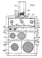
- FIGURE 1 is a front elevation of a cable transit according to this invention shown in the assembled condition with cables in situ;
- FIGURE 2 is a partly sectioned side view of the cable transit shown in Figure 1;
- FIGURE 3 is an isometric detail view showing the packer blocks, support plates and distance member of the compression and packer assembly;
- FIGURE 4 is an isometric detail view of the plate of the compression and packer assembly;
- FIGURE 5 is an isometric detail view showing an alternative type of packer blocks and support plates;
- FIGURE 6 is a detail sectional view of part of the assembly shown in Figure 5 and as indicated therein;
- FIGURE 7 is an isometric detail view showing another alternative type of packer blocks and a support plate;
- FIGURE 8 is a front elevational view of a frame having an integral support plate;
- FIGURE 9 is a side view of the frame shown in Figure 8;
- FIGURE 10 is a top plan view of the frame shown in Figure 8; and
- FIGURE 11 is a front elevation of a cable transit similar to that shown in Figure 1 but in which the support plates for the packer blocks are different and in which a detail section of the distance member is depicted.
- With reference to the general views of the complete cable transit as shown in the drawings of Figures 1,2 and 10, the improved cable transit comprises a
rectangular frame 1 defining anopening 2 through whichcables 3 of different sizes extend. In known manner, eachcable 3 is held within a lead-throughblock 4 whilst solidblank blocks 5 fill the modular spaces of the opening where no cable is present. Each lead-throughblock 4 comprises two complementary half-blocks 40 which have semi-cylindrical recesses that define a passageway or lead-through for thecable 3. The frame is for mounting or support in an aperture in a bulkhead or partition or the like (not shown) and the numbers and sizes of cables may vary from one installation to another. For simplicity of explanation of this invention, only a small number of cables are depicted and the assembly is not as complex as found in practice where tens of cables may have to be accommodated and installed at the site location. - In this embodiment, there is depicted three series of sized sets of
modular blocks opening 2 and theframe 1. Each series set has blocks of substantially square section with the respective width and height dimensions of each set being selected to a common multiple so that a plurality of blocks of each set will complete a row or fill a modular space within the frame. Typical suitable modular dimensions are 90mm, 60mm and 30mm for the square section blocks. - Each set of modular blocks is assembled in a row and to separate and support the assembled rows, stay
plates 6 extend therebetween to locate on the marginal edges of the side walls of theframe 1. - In addition, the
opening 2 is closed by a compression andpacker assembly 7 which is for clamping and holding the rows of modular blocks in place and applies pressure to the modular blocks to seal these both to thecables 3, to each other, to the inner faces of theframe 1 and to thestay plates 6. - With reference also to Figures 3 and 4, the compression and
packer assembly 7 comprises apressure plate 8, threepacker blocks respective compressor stud packer block rear support plate respective stud stud front support plate 18 withrespective nuts front support plate 18. - The
pressure plate 8 is a rigid body having aplanar underside 22 for engagement with the upper faces of the top row ofblocks 4a and 5a, and anedge flange 23 on each side of theplate 8 provides location ledges over-lying the upper marginal edges of the blocks as well as providing outer end lug portions that extend outwardly and engage the outer faces of the sides of theframe 1. The topside of theplate 8 has a flatcentral portion 24 and opposedinclined portions 25. - Each of the packer blocks 9,10 and 11 are made of a resilient material and the
outer blocks 9 and 11 have respective throughholes compression studs limit pin 28 is mounted in each throughhole pin 28 is arranged to engage the inner face of theupper end wall 29 of theframe 1 and the inclined portion of thepressure plate 8 so as to limit the degree of deformation of theblocks 9 and 11 when a reactive load is applied to the blocks in the direction of the axis of the limit pins as later explained. - The
upper end wall 29 of theframe 1 is provided with acentral clearance hole 30. A hexagonal shapedboss 31 is rigidly mounted on thewall 29 and projects therefrom aligned with theclearance hole 30. The boss has an internal blind threaded bore 32 and acompression bolt 33 is in threaded engagement within thebore 32 with thehead 34 of thebolt 33 being accessible through theclearance hole 30 for rotation by a suitable tool. As should be appreciated, thebolt 34 can be unthreaded to extend into the void below theboss 31 when thecentral packer block 10 is not fitted, and thehead 34 of the bolt will engage with thecentral portion 24 of theplate 8. - The packer blocks 9 and 11 are similar and have inner side faces that lie adjacent to the opposed side faces of the
central packer block 10. The side faces of all the packer blocks 9,10 and 11 as shown in Figure 3 are parallel to each other and normal to their top or upper faces remote from theplate 8. Thecentral packer block 10 has aflat underside face 35 engaging the flatcentral portion 24 of theplate 8. The underside faces of the packer blocks 9 and 11 are inclined relative to the upper or top faces and are complementary to the respectiveinclined portions 25 of theplate 8. - The cable transit as aforedescribed with reference to the first arrangement of the packer blocks as shown in Figure 5 is assembled from the individual components by a fitter in the manner now to be described.
- Firstly, the
frame 1 is located in the structure with the runs ofcables 3 extending through theopening 2 of theframe 1. The fitter is presumed to have the selection of modular lead-throughblocks 4 for each cable and a number of blanking blocks 5. - As depicted in Figure 1, the largest lead-through blocks 4c are used in the lower row, and firstly the lower half-blocks 40c are set against the bottom inner wall of the
frame 1 and therespective cables 3 are seated in the semi-cylindrical recesses in the half-blocks 40c and the upper half-blocks 40c are then seated on top to form the lead-throughblocks 4 closing over thecables 3. Thestay plate 6 is then inserted in place on top of this lower row of blocks with the marginal flanged edges of thestay plate 6 riding over the side edges of theframe 1 to locate thestay plate 6 in a similar manner as for thepressure plate 8. Preferably, the stay plate has a central web portion which is pierced or of mesh to prevent high rates of heat transfer from one side to the other of the cable transit when installed. - The fitter then selects the
next cables 3 to be located in the lead-through blocks 4b for the next row and this row includes a solid blanking block 5b. The assembly is as for the first row, and when the blocks 4b and block 5b are assembled anotherstay plate 6 is located over the row of blocks. - The third row of
blocks 4a, and 5a is then assembled in a similar manner, and all of the cable runs are enclosed by the selected lead-throughblocks 4 and modular spaces are filled by thesolid blocks 5a. The lower portion of the frame opening is filled by the rows of blocks and stayplates 6. - Once this assembly has been completed by the fitter, it is then necessary to apply pressure to the assembled blocks and cables to clamp and seal the blocks together as well as to seal such sized lead-through blocks to the cable. In addition, the remainder of the opening in the
frame 1 must be closed or filled. This next stage to complete the assembly is by the component parts of the compression and packer assembly. - The
pressure plate 8 is located over the third row of blocks and seated over the assembled array of blocks and cables. Due to the resilient nature of the blocks and the effect of the cables, pressure must be applied to the assembled blocks to compress the blocks around the cables to seal the lead-through blocks both around the cable and to clamp them together and against the side walls of theframe 1 and to thestay plates 6. - To apply this pressure, the
compression bolt 33 is rotated to bring thehead 34 into engagement with the flatcentral portion 24 of theplate 8 and on further rotation of thehead 34 compressive forces are applied through theplate 8 to the assembled blocks. - Once the compressive load applied to the
plate 8 is sufficient to leave a clearance space between thepressure plate 8 and the inner face of thetop frame wall 29, the fitter can insert anouter packer block 9 or 11 in the clearance space clear of the compression bolt which only extends to the centre of the clearance space and does not interfere with the fitting of either of the twoside blocks 9 and 11. - Following the insertion of one or both of the two side packer blocks 9 and 11, the
compression bolt 33 can be counter-rotated to return the bolt into the bore of theboss 31 leaving the central area over thepressure plate 8 free for insertion of thecentral packer block 10 between the twoside blocks 9 and 11. The assembly of the rows of blocks and cables will continue to exert reactive forces on thepressure plate 8 tending to displace it towards the top wall of the frame, and thus tending to compress theblocks 9 and 11. To obviate the affect of these reactive forces, the limit pins 28 of defined length mounted in the packer blocks 9 and 11 restrict squeezing of the packer blocks because the opposed ends of thepins 28 will abut the rigid surfaces of theplate 8 and theend wall 29. - Once the three
packer blocks front support plate 18 can be engaged over the free ends of each of thecompressor studs respective nuts support plate 18. On tightening of the nuts, each of the packer blocks 9,10 and 11 is squeezed so as to cause resilient displacement of the block material in a direction transverse to the axis of each compressor stud thereby expanding the assembly both to fill the clearance opening between thepressure plate 8 and theframe 1 and to exert the required clamping pressure onto the assembly of blocks and cables beneath thepressure plate 8. - Accordingly, the compression and
packer assembly 7 completes the filling of theopening 2 in theframe 1 whilst also applying the necessary forces to the assembled rows of blocks and cables to ensure that the whole assembly is sealed together and securely located against displacement. The forces applied to the assembled rows of the lead-through and blank blocks are sufficient to ensure each lead-through block is in clamping and sealing engagement with the cable. - As will be appreciated from the foregoing description of the manner of fitting the component parts of the compression and
packer assembly 7, the fitter can fit all of the parts together from the front of the frame where access to the rear of the frame is precluded as often happens when the frame is fitted in a closed bulkhead. The over-loading of the packing blocks by reactive forces applied by the natural resilience of the modular blocks and the cables is limited by the limit pins, and the limit pins do not interfere with the expansion of the packer blocks 9,11 when the compressor bolts are tightened. - With reference now to the alternative form of the packer blocks as depicted in Figure 5, it should be noted that the
outer blocks 9 and 11 each have inner side faces 9a,11a that are not normal to the upper or top face of the respective blocks. The inner side faces 9a,11a are inclined or tapered towards the rear support plates as well as being divergent from the upper or top faces so as to have a wedge-like inner form. Each side face 10a of the central packer block has complementary inclined and taper faces which diverge towards therear support plate 16. - In this alternative form of the packer blocks, the assembly of the compression and packer component parts may proceed as just described for the arrangement depicted in Figure 3 if there is access to both sides of the transit frame. If the access is limited to the front, then the fitter would insert one of the side packer blocks 9 or 11 first, then insert the
central packer block 10 and lastly insert the other side packer block which, with it's wedge-like shape is presented with it's smaller end to the space left for insertion and can be easily inserted and slid into place. Once thesupport plate 18 is located over the free ends of thecompressor studs respective nuts - As various installations and requirements arise in practice, it will be understood that although the two alternative forms of packer blocks and support plates as just described are suitable for some applications, it is also possible for each packer block to have an independent support plate both at the rear and front. Such an alternative is depicted in Figure 11 where the front support plate comprises three separate plates respectively referenced as
plate 118 for the outer packer blocks, and asplate 218 for the central packer block. - Although all of the alternatives as have been described include one or more support plates for the packer blocks which are separate from the frame, an alternative is shown in Figures 7,8,9 and 10 to which reference will now be made and wherein the same references as used for similar parts as previously described.
- The
frame 1 has asupport plate 50 rigidly secured to theside walls 51 and theend wall 29 so as to extend across the rear face of the upper portion of theframe 1. The support plate is provided with three throughbores - The packer blocks 9,10 and 11 as shown in Figure 7 are each formed with through bores of which one 10c is shown in dashed lines, and each of the bores provide through passageways for the respective compressor studs of which the free ends are to project through aligned holes in the
front support plate 18, and in the same manner as previously described, a nut would be mounted on the free end of each stud to compress the packer blocks to the desired degree when the assembly was completed. - The studs could be rigidly fixed to project from the rear support plate, or the
bores support plate 50, the bores therethrough are threaded and the compressor studs are entered through the front of the packer blocks and any associated front support plate(s) overlying the packer blocks. All of these possibilities are capable of performance with the improved form of compression and packer assembly. - It should also be noted that the packer blocks as shown in Figure 7 include another important variation. In these packer blocks, the side blocks 9 and 11 have respective inner side faces 9b and 11b which are both tapering inwardly in the direction of the forward end shown nearest to the
support plate 18, and in addition, these faces are inclined inwardly towards thecentral packer block 10 so that each side packer block is of wedge-like shape being smaller at the forward end. Thecentral block 10 has complementary inclined side faces 10b and the central block is thus of wedge-like shape with the smaller end of the wedge being inwards. - Accordingly, with this arrangement of packer blocks, each of the side packer blocks 9 and 11 can be fitted into the clearance space between the
plate 8 whilst the compression bolt is engaged with theplate 8. Once thecompression bolt 8 has been displaced back into theboss 31, then thecentral packer block 10 can be presented with the smaller end first and slid into place with the compressor stud extending through the bore 10c. - Other combinations of the component parts of the compression and packer assemblies as just described are feasible, and it is assumed that these will be appreciated by those skilled in this field.
- Other alternatives within the scope of this invention include the provision of distance members which are not limit pins disposed within bores or holes through a packer block.
- It is envisaged that the support plates associated with at least one packer block could be sized and designed for abutment with the pressure plate and the frame so as to provide the necessary limit to compression of the packer block when the load applied by the compression bolt is relieved. Alternatively, separate short plates like spacers could be provided for interim temporary placement between the plate and inner wall of the frame.
- In the preferred embodiments of this invention as described and illustrated, there have been three packer blocks with respective compressor studs and support plates. It is possible to apply the principles explained herein to only two packer blocks if one packer block is larger than the other so that the smaller packer block is fitted first and after relieving the pressure exerted by the compression bolt on the plate, then the second larger packer block could be inserted in the remaining clearance space to be filled. Following the same principle, it is possible to have more than three packer blocks, and depending on the way in which these are arranged, it is possible to have one or more of these also with wedge-like shape to facilitate fitting and distributing loading over wedge faces.
- As will be understood, the fitting of the cable transit arises in various environments, and the cable transit may be installed as described in the vertical position, but it may be installed horizontally where safe retention and ease of assembly of the blocks and other component parts is required.
- The exemplary embodiments described are simplified for an understanding of this invention, and the numbers and relative dimensions of the blocks may be varied whilst maintaining the principles of modular sizes, and of course in known manner, more than one block may fill a modular space, for instance four small blocks as shown in row a may fill a modular space in row c.
- The resilient material of which the lead-through and blanking blocks as well as the packer blocks are made can be of any suitable material which is flame-resistant, fire-resistant, water-resistant and resistant to effects of rodent attack, ageing, and temperature variations.
- Throughout this description, reference has been made to cables as this is the commonest form of use of transits through bulkheads, partitions or the like. However, the invented cable transit can be used and applied to pipes or conduits and the term "cable" is not intended to be a limitation to the application and use of the invention nor is the use of the term "cable" to be interpreted as a limitation to the scope of this invention.
- In our co-pending European Patent Application No.0,236,728 we describe and claim a lead-through transit for cables and the like in which the cable blocks are adapted to accommodate a range of cable sizes.
Claims (10)
- A lead-through transit of the kind comprising a rectangular metal frame (1) defining an opening (2) through which cables or pipes (3) are to extend, a series of sets of modular blocks (4,5) for assembly in rows within the frame opening (2) between opposed sidewalls of the frame (1), the blocks (4,5) being adapted for surrounding respectively each cable or for blanking off a modular space, a rigid pressure plate (8) for location in the frame opening (2) between the sidewalls of the frame (1), a compression bolt (33) mounted in an end wall (29) of the frame (1) for threaded displacement in a first direction which is in a plane transverse to the axes of the cables (3) for engagement with the plate (8) to apply a load to the plate (8) to clamp the assembled array of modular blocks (4,5) and cables (3) together, packer blocks (9,10,11) of resilient material for insertion into a clearance space in the frame opening (2) between the end wall (29) and the plate (8) in a second direction which is transverse to said first direction and in a plane substantially parallel to the axes of the cables (3), and compressor studs (12,13,14) extending in the second direction through the packer blocks (9,10,11) and arranged to apply compression to the packer blocks (9,10,11) within the confines of the frame (1) to maintain pressure on the plate (8) and assembled array of modular blocks (4,5) and cables (3) characterised in that the packer blocks (9,10,11) include at least one packer block (9,11) that is inserted into the clearance space beside the compression bolt (33) when engaged with the plate (8) to partially fill the clearance space, and at least one packer block (10) that is inserted into the clearance space after the compression bolt (33) has been displaced from engagement with the plate (8) clear of the frame opening (2) such that the packer blocks (9,10,11) are seated beside each other between the side walls of the frame (1) and completely fill the clearance space.
- A transit according to Claim 1 further characterised in that a distance member (28) is interposed between the end wall (29) of the frame (1) and the plate (8) to limit the reactive effect of the assembled modular blocks and cables on the plate (8) on displacement of the compression bolt (33) away from the plate (8) following insertion of at least one packer block (9,11).
- A transit according to Claim 2 further characterised in that the distance member (28) comprises a pin located within a bore (26,27) formed in said at least one packer block (9,11).
- A transit according to any one of the preceding Claims further characterised in that there are three packer blocks comprising a central packer block (10) and two outer or side packer blocks (9,11), the outer or side packer blocks (9,11) being clear of the extent of the compression bolt (33) when engaged with the plate (8).
- A transit according to Claim 4 further characterised in that the packer blocks (9,10,11) have complementary taper faces (9a,10a,11a) (9b,10b,11b) for abutting engagement with each other on insertion of each packer block (9,10,11) into position within the clearance space between the end wall (29) of the frame (1) and the plate (8).
- A transit according to Claim 5 further characterised in that the taper faces (9a,10a,11a) (9b,10b,11b) of the packer blocks (9,10,11) are inclined either to the first direction and/or inclined to the second direction, and that these taper faces (9a,10a,11a) (9b,10b,11b) are arranged to provide a wedge-like effect between the packer blocks (9,10,11).
- A transit according to any one of the preceding Claims further characterised in that each packer block (9,10,11) is arranged between opposed support plates (15,16,17,18;50,118,128) and has a compressor stud (12,13,14) extending therethrough in the second direction to connect the support plates (15,16,17,18;50,118,128) to apply compression to the packer block (9,10,11).
- A transit according to any one of the preceding Claims further characterised in that the pressure plate (8) has a flat underside face (22) arranged to engage with the row of modular blocks (4,5) as last assembled and the opposed face of the pressure plate (8) has opposed taper faces (25) that are tapering towards the sides of the frame (1) from a central portion (24) and the underside faces of the packer blocks (9,10,11) have a conformation complementary thereto.
- A transit according to any one of the preceding Claims further characterised in that the compression bolt (33) is in threaded engagement with a boss (31) rigidly mounted on the end wall (29) of the frame (1) with the frame having a clearance opening (30) leading to a threaded bore (32) in the boss (31) into which the compression bolt (33) can be displaced.
- A transit according to Claim 1 further characterised in that there are two packer blocks comprising one of smaller size for insertion into the clearance space beside the compression bolt (33) when engaged with the pressure plate (8) and one of larger size for insertion into the clearance space to complete filling of the frame opening (2) after the compression bolt (33) has been displaced from engagement with the plate (8) clear of the frame opening (2).
Priority Applications (1)
| Application Number | Priority Date | Filing Date | Title |
|---|---|---|---|
| AT87101464T ATE83093T1 (en) | 1986-02-11 | 1987-02-04 | PASSAGE FOR CABLES AND PIPES. |
Applications Claiming Priority (2)
| Application Number | Priority Date | Filing Date | Title |
|---|---|---|---|
| GB8603369A GB2186441B (en) | 1986-02-11 | 1986-02-11 | Improved transit for cables and pipes |
| GB8603369 | 1986-02-11 |
Publications (3)
| Publication Number | Publication Date |
|---|---|
| EP0232839A2 EP0232839A2 (en) | 1987-08-19 |
| EP0232839A3 EP0232839A3 (en) | 1989-05-31 |
| EP0232839B1 true EP0232839B1 (en) | 1992-12-02 |
Family
ID=10592879
Family Applications (1)
| Application Number | Title | Priority Date | Filing Date |
|---|---|---|---|
| EP87101464A Expired - Lifetime EP0232839B1 (en) | 1986-02-11 | 1987-02-04 | Improved transit for cables and pipes |
Country Status (5)
| Country | Link |
|---|---|
| US (1) | US4733016A (en) |
| EP (1) | EP0232839B1 (en) |
| AT (1) | ATE83093T1 (en) |
| DE (1) | DE3782832T2 (en) |
| GB (1) | GB2186441B (en) |
Families Citing this family (32)
| Publication number | Priority date | Publication date | Assignee | Title |
|---|---|---|---|---|
| DE3727160C1 (en) * | 1987-08-14 | 1988-09-08 | Plastoform Gmbh & Co Kg | Lead-through for cables through a wall opening |
| AT391044B (en) * | 1987-09-09 | 1990-08-10 | Doepfl Rudolf Gmbh | DEVICE FOR PRESSING PACKAGES IN A FRAME FOR THE PRODUCTION OF CABLE GLANDS |
| US5007701A (en) * | 1989-06-29 | 1991-04-16 | Windsor Communications, Inc. | Splice closure apparatus |
| US5783776A (en) * | 1991-10-29 | 1998-07-21 | O-Z Gedney Company Llc | Electrical cable penetration seal with compliant module |
| US5416271A (en) * | 1991-10-29 | 1995-05-16 | General Signal Corporation | Electrical cable penetration seal with compliant module |
| GB2275577B (en) * | 1993-02-26 | 1996-05-29 | Hawke Cable Glands Ltd | Improvements in or relating to transits |
| MY112885A (en) * | 1993-12-01 | 2001-10-31 | N V Raychem S A | Sealing device. |
| WO1995031025A1 (en) * | 1994-05-04 | 1995-11-16 | General Signal Corporation | Electrical cable penetration seal with compliant module |
| SE9403381L (en) * | 1994-10-06 | 1996-04-01 | Roxtec Ab | Cable bushing |
| US6053456A (en) * | 1998-06-29 | 2000-04-25 | Lucent Technologies Inc. | Cable anchor assembly |
| DE10150075A1 (en) * | 2001-10-10 | 2003-04-17 | Roxtec Ingenieur Gmbh | Module for a sealed passage for cables/pipes, through constructions, has a lateral recess around its outer sealing surfaces with at least one drilling to the interior to test the hermetic sealing |
| SE528099C2 (en) * | 2004-01-30 | 2006-09-05 | Roxtec Ab | Compression unit for a frame that receives compressible tubing insertion units |
| ES2324825T3 (en) * | 2004-08-24 | 2009-08-17 | Mct Brattberg Ab | FIRE PROTECTION PROVISION FOR INSTALLATION IN A TABIQUE. |
| CN100461568C (en) * | 2007-05-10 | 2009-02-11 | 张东升 | Clamping mechanism for cable through-going device |
| SE532027C2 (en) * | 2008-02-15 | 2009-10-06 | Roxtec Ab | Feed-through frame with integrated compression unit |
| US8294030B2 (en) * | 2008-11-18 | 2012-10-23 | MP Husky | Cable bus support block and system |
| US20100123048A1 (en) * | 2008-11-18 | 2010-05-20 | Pollard Jr Michael E | Cable bus support block and system |
| CN104344097A (en) * | 2008-12-18 | 2015-02-11 | 上海卓尤化工科技有限公司 | Rubber composition for elastomer module and preparation method and elastomer module thereof |
| SE533818C2 (en) * | 2009-02-04 | 2011-01-25 | Roxtec Ab | Eccentric part of a pipe or cable entry |
| SE535015C2 (en) * | 2009-02-04 | 2012-03-13 | Roxtec Ab | Compressible seal or bushing and sealing system |
| SE533541C2 (en) * | 2009-02-04 | 2010-10-19 | Roxtec Ab | Lubrication of a pipe or cable entry |
| SE0950475A1 (en) * | 2009-06-18 | 2010-11-16 | Roxtec Ab | EMC-protected compression unit and a sealing system comprising such a compression unit |
| FI20105720A0 (en) * | 2010-06-22 | 2010-06-22 | Trelleborg Ind Products Finlan | Kabelgenomföringsfläns |
| US9142946B2 (en) * | 2013-06-27 | 2015-09-22 | Caterpillar Inc. | Cable retention system |
| NL1040892B1 (en) * | 2014-07-16 | 2016-08-16 | Beele Eng Bv | System for holding in a conduit cables or ducts with different diameters. |
| EP3235357B1 (en) * | 2014-12-19 | 2023-06-07 | Hans-Erik Johansson I Hagstad Aktiebolag | Feed-through |
| CN105033941B (en) * | 2015-08-27 | 2017-03-22 | 上海怡博船务有限公司 | Gantry type installation fixture |
| WO2017046064A1 (en) * | 2015-09-14 | 2017-03-23 | CommScope Connectivity Belgium BVBA | Sealing block arrangements for enclosures |
| US10476250B2 (en) * | 2015-09-14 | 2019-11-12 | CommScope Connectivity Belgium BVBA | Sealing block arrangements for enclosures |
| US11837860B2 (en) * | 2020-10-22 | 2023-12-05 | Quanta Computer Inc. | Cable-gland system for an electronic chassis providing enhanced sealing functionality |
| SE545999C2 (en) * | 2021-06-30 | 2024-04-09 | Roxtec Ab | A sealing module for cables or pipes, a transit system comprising such a sealing module, and a method of manufacturing a sealing module |
| SE546693C2 (en) * | 2023-06-15 | 2025-02-11 | Roxtec Ab | A transit device and system for leading cables or pipes through a partition and use thereof |
Family Cites Families (9)
| Publication number | Priority date | Publication date | Assignee | Title |
|---|---|---|---|---|
| US2732226A (en) * | 1956-01-24 | Brattberg | ||
| US3282544A (en) * | 1963-03-11 | 1966-11-01 | Lyckeaborgs Bruk Ab | Tight lead-through inlet frame device for electrical lines |
| SE415619B (en) * | 1979-01-18 | 1980-10-13 | Lyckeaborgs Bruk Ab | TRANSFER FOR FIRE SAFETY PRESENTATION OF ELECTRICAL CABLES THROUGH A WALL OR SIMILAR OPENING |
| US4249353A (en) * | 1979-02-27 | 1981-02-10 | Crouse-Hinds Company | Fire barrier assembly for electrical cable |
| DE2909890C2 (en) * | 1979-03-14 | 1982-05-27 | System- Und Verfahrenstechnik Verwaltungsgesellschaft Mbh, 2105 Seevetal | Device for shielding high-frequency electrical and electromagnetic waves in tight bushings for bundles of cables through a wall |
| US4262166A (en) * | 1979-09-24 | 1981-04-14 | Radzishevsky Oleg L | Sealed inlet for bunched conductors |
| ATE50669T1 (en) * | 1984-02-28 | 1990-03-15 | Werner Hauff | PASS AT LEAST ONE ELECTRICAL CABLE THROUGH A WALL OPENING. |
| SE441795B (en) * | 1984-03-23 | 1985-11-04 | Lyckeaborgs Bruk Ab | PROTECTIVE DEVICE FOR DUMPING PULSE-SHAPED HIGH-FREQUENCY, ELECTROMAGNETIC RADIATION PASSAGE THROUGH A FIRE-PROTECTIVE TRANSFER |
| NL8403650A (en) * | 1984-11-30 | 1986-06-16 | Johannes Alfred Beele | TRANSIT DEVICE. |
-
1986
- 1986-02-11 GB GB8603369A patent/GB2186441B/en not_active Expired - Lifetime
-
1987
- 1987-02-02 US US07/009,943 patent/US4733016A/en not_active Expired - Lifetime
- 1987-02-04 EP EP87101464A patent/EP0232839B1/en not_active Expired - Lifetime
- 1987-02-04 AT AT87101464T patent/ATE83093T1/en active
- 1987-02-04 DE DE8787101464T patent/DE3782832T2/en not_active Expired - Fee Related
Also Published As
| Publication number | Publication date |
|---|---|
| GB2186441B (en) | 1990-01-10 |
| US4733016A (en) | 1988-03-22 |
| ATE83093T1 (en) | 1992-12-15 |
| EP0232839A2 (en) | 1987-08-19 |
| GB2186441A (en) | 1987-08-12 |
| EP0232839A3 (en) | 1989-05-31 |
| DE3782832T2 (en) | 1993-05-27 |
| GB8603369D0 (en) | 1986-03-19 |
| DE3782832D1 (en) | 1993-01-14 |
Similar Documents
| Publication | Publication Date | Title |
|---|---|---|
| US4733016A (en) | Transit for cables and pipes | |
| US4919372A (en) | Transit for cables and pipes | |
| GB2186443A (en) | Transit for cables and pipes | |
| GB2204922A (en) | Improved transit for cables and pipes | |
| US4889298A (en) | Wall feedthrough fitting | |
| US5286211A (en) | Ground connector | |
| US2813692A (en) | Sealed bulkhead installations of electric wires | |
| US5422436A (en) | Control cabinet | |
| US3976825A (en) | Lead-through for electric cables and the like | |
| US4272643A (en) | Fire resistant fitting | |
| EP1222722B1 (en) | A cable penetration device | |
| US4365907A (en) | Fastening devices | |
| GB2140114A (en) | Feed-through for cables and pipes | |
| KR101178224B1 (en) | Bracket of connecting for electric power cable in underground | |
| KR100976990B1 (en) | Tendon anchoring apparatus and precast concrete box culvert having tendon anchoring apparatus and precast concrete box culvert method thereof | |
| CH688012A5 (en) | Cable fixing device for electrical wall socket | |
| US5220131A (en) | Poke-through fire barrier structure with knock-out openings | |
| KR100880692B1 (en) | Wire rod connection metal parts, mounting fixture and mounting | |
| EP0612946A1 (en) | Improvements in or relating to transits | |
| CN218603137U (en) | Wall-penetrating cable seepage-proofing sealing structure | |
| CN222996191U (en) | An all-purpose combinable fire blocking kit | |
| DE4240001A1 (en) | Multi-phase branch terminal | |
| CN115498571A (en) | Anti-seepage sealing structure for wall-penetrating cable and construction method thereof | |
| RU172452U1 (en) | Cable Gland Clamp | |
| RU212135U1 (en) | A WEDGE MECHANISM AND A GATE SYSTEM CONTAINING SUCH A WEDGE MECHANISM |
Legal Events
| Date | Code | Title | Description |
|---|---|---|---|
| PUAI | Public reference made under article 153(3) epc to a published international application that has entered the european phase |
Free format text: ORIGINAL CODE: 0009012 |
|
| AK | Designated contracting states |
Kind code of ref document: A2 Designated state(s): AT BE CH DE ES FR IT LI LU NL SE |
|
| PUAL | Search report despatched |
Free format text: ORIGINAL CODE: 0009013 |
|
| AK | Designated contracting states |
Kind code of ref document: A3 Designated state(s): AT BE CH DE ES FR IT LI LU NL SE |
|
| 17P | Request for examination filed |
Effective date: 19891109 |
|
| 17Q | First examination report despatched |
Effective date: 19911023 |
|
| GRAA | (expected) grant |
Free format text: ORIGINAL CODE: 0009210 |
|
| AK | Designated contracting states |
Kind code of ref document: B1 Designated state(s): AT BE CH DE ES FR IT LI LU NL SE |
|
| PG25 | Lapsed in a contracting state [announced via postgrant information from national office to epo] |
Ref country code: IT Free format text: LAPSE BECAUSE OF FAILURE TO SUBMIT A TRANSLATION OF THE DESCRIPTION OR TO PAY THE FEE WITHIN THE PRESCRIBED TIME-LIMIT;WARNING: LAPSES OF ITALIAN PATENTS WITH EFFECTIVE DATE BEFORE 2007 MAY HAVE OCCURRED AT ANY TIME BEFORE 2007. THE CORRECT EFFECTIVE DATE MAY BE DIFFERENT FROM THE ONE RECORDED. Effective date: 19921202 Ref country code: BE Effective date: 19921202 |
|
| REF | Corresponds to: |
Ref document number: 83093 Country of ref document: AT Date of ref document: 19921215 Kind code of ref document: T |
|
| REF | Corresponds to: |
Ref document number: 3782832 Country of ref document: DE Date of ref document: 19930114 |
|
| PG25 | Lapsed in a contracting state [announced via postgrant information from national office to epo] |
Ref country code: LU Free format text: LAPSE BECAUSE OF NON-PAYMENT OF DUE FEES Effective date: 19930228 |
|
| ET | Fr: translation filed | ||
| PG25 | Lapsed in a contracting state [announced via postgrant information from national office to epo] |
Ref country code: ES Free format text: LAPSE BECAUSE OF FAILURE TO SUBMIT A TRANSLATION OF THE DESCRIPTION OR TO PAY THE FEE WITHIN THE PRESCRIBED TIME-LIMIT Effective date: 19930313 |
|
| PLBE | No opposition filed within time limit |
Free format text: ORIGINAL CODE: 0009261 |
|
| STAA | Information on the status of an ep patent application or granted ep patent |
Free format text: STATUS: NO OPPOSITION FILED WITHIN TIME LIMIT |
|
| 26N | No opposition filed | ||
| EAL | Se: european patent in force in sweden |
Ref document number: 87101464.3 |
|
| PGFP | Annual fee paid to national office [announced via postgrant information from national office to epo] |
Ref country code: FR Payment date: 20000131 Year of fee payment: 14 |
|
| PGFP | Annual fee paid to national office [announced via postgrant information from national office to epo] |
Ref country code: CH Payment date: 20000209 Year of fee payment: 14 |
|
| PGFP | Annual fee paid to national office [announced via postgrant information from national office to epo] |
Ref country code: SE Payment date: 20000218 Year of fee payment: 14 |
|
| PGFP | Annual fee paid to national office [announced via postgrant information from national office to epo] |
Ref country code: AT Payment date: 20000229 Year of fee payment: 14 Ref country code: NL Payment date: 20000229 Year of fee payment: 14 |
|
| PGFP | Annual fee paid to national office [announced via postgrant information from national office to epo] |
Ref country code: DE Payment date: 20000420 Year of fee payment: 14 |
|
| PG25 | Lapsed in a contracting state [announced via postgrant information from national office to epo] |
Ref country code: AT Free format text: LAPSE BECAUSE OF NON-PAYMENT OF DUE FEES Effective date: 20010204 |
|
| PG25 | Lapsed in a contracting state [announced via postgrant information from national office to epo] |
Ref country code: SE Free format text: LAPSE BECAUSE OF NON-PAYMENT OF DUE FEES Effective date: 20010205 |
|
| PG25 | Lapsed in a contracting state [announced via postgrant information from national office to epo] |
Ref country code: CH Free format text: LAPSE BECAUSE OF NON-PAYMENT OF DUE FEES Effective date: 20010228 Ref country code: LI Free format text: LAPSE BECAUSE OF NON-PAYMENT OF DUE FEES Effective date: 20010228 |
|
| PG25 | Lapsed in a contracting state [announced via postgrant information from national office to epo] |
Ref country code: NL Free format text: LAPSE BECAUSE OF NON-PAYMENT OF DUE FEES Effective date: 20010901 |
|
| REG | Reference to a national code |
Ref country code: CH Ref legal event code: PL |
|
| EUG | Se: european patent has lapsed |
Ref document number: 87101464.3 |
|
| PG25 | Lapsed in a contracting state [announced via postgrant information from national office to epo] |
Ref country code: FR Free format text: LAPSE BECAUSE OF NON-PAYMENT OF DUE FEES Effective date: 20011031 |
|
| NLV4 | Nl: lapsed or anulled due to non-payment of the annual fee |
Effective date: 20010901 |
|
| REG | Reference to a national code |
Ref country code: FR Ref legal event code: ST |
|
| PG25 | Lapsed in a contracting state [announced via postgrant information from national office to epo] |
Ref country code: DE Free format text: LAPSE BECAUSE OF NON-PAYMENT OF DUE FEES Effective date: 20011201 |