EP0232599B1 - Automatic infiltration detection system - Google Patents
Automatic infiltration detection system Download PDFInfo
- Publication number
- EP0232599B1 EP0232599B1 EP86309164A EP86309164A EP0232599B1 EP 0232599 B1 EP0232599 B1 EP 0232599B1 EP 86309164 A EP86309164 A EP 86309164A EP 86309164 A EP86309164 A EP 86309164A EP 0232599 B1 EP0232599 B1 EP 0232599B1
- Authority
- EP
- European Patent Office
- Prior art keywords
- infusion
- flowable material
- pressure
- test pulse
- pressure wave
- Prior art date
- Legal status (The legal status is an assumption and is not a legal conclusion. Google has not performed a legal analysis and makes no representation as to the accuracy of the status listed.)
- Expired
Links
- 230000008595 infiltration Effects 0.000 title claims description 23
- 238000001764 infiltration Methods 0.000 title claims description 23
- 238000001514 detection method Methods 0.000 title claims description 7
- 238000001802 infusion Methods 0.000 claims description 123
- 230000004044 response Effects 0.000 claims description 54
- 238000012360 testing method Methods 0.000 claims description 50
- 230000009969 flowable effect Effects 0.000 claims description 38
- 239000000463 material Substances 0.000 claims description 38
- 230000008859 change Effects 0.000 claims description 18
- 208000034423 Delivery Diseases 0.000 claims description 14
- 238000012544 monitoring process Methods 0.000 claims description 4
- 230000000246 remedial effect Effects 0.000 claims description 3
- 238000005070 sampling Methods 0.000 claims description 3
- 230000007423 decrease Effects 0.000 claims description 2
- 239000012530 fluid Substances 0.000 description 7
- 230000002572 peristaltic effect Effects 0.000 description 7
- 230000000694 effects Effects 0.000 description 4
- 230000003750 conditioning effect Effects 0.000 description 3
- 230000000630 rising effect Effects 0.000 description 3
- 230000002792 vascular Effects 0.000 description 3
- 230000008901 benefit Effects 0.000 description 2
- 210000000748 cardiovascular system Anatomy 0.000 description 1
- 238000004891 communication Methods 0.000 description 1
- 230000001143 conditioned effect Effects 0.000 description 1
- 238000010276 construction Methods 0.000 description 1
- 238000010586 diagram Methods 0.000 description 1
- 238000006073 displacement reaction Methods 0.000 description 1
- 238000011156 evaluation Methods 0.000 description 1
- 230000000977 initiatory effect Effects 0.000 description 1
- 238000003780 insertion Methods 0.000 description 1
- 230000037431 insertion Effects 0.000 description 1
- 239000007788 liquid Substances 0.000 description 1
- 238000000034 method Methods 0.000 description 1
- 238000012986 modification Methods 0.000 description 1
- 230000004048 modification Effects 0.000 description 1
- 230000000737 periodic effect Effects 0.000 description 1
- 230000009467 reduction Effects 0.000 description 1
- 230000008054 signal transmission Effects 0.000 description 1
- 238000006467 substitution reaction Methods 0.000 description 1
- 210000003462 vein Anatomy 0.000 description 1
- 230000000007 visual effect Effects 0.000 description 1
Images
Classifications
-
- A—HUMAN NECESSITIES
- A61—MEDICAL OR VETERINARY SCIENCE; HYGIENE
- A61M—DEVICES FOR INTRODUCING MEDIA INTO, OR ONTO, THE BODY; DEVICES FOR TRANSDUCING BODY MEDIA OR FOR TAKING MEDIA FROM THE BODY; DEVICES FOR PRODUCING OR ENDING SLEEP OR STUPOR
- A61M5/00—Devices for bringing media into the body in a subcutaneous, intra-vascular or intramuscular way; Accessories therefor, e.g. filling or cleaning devices, arm-rests
- A61M5/14—Infusion devices, e.g. infusing by gravity; Blood infusion; Accessories therefor
- A61M5/168—Means for controlling media flow to the body or for metering media to the body, e.g. drip meters, counters ; Monitoring media flow to the body
- A61M5/16831—Monitoring, detecting, signalling or eliminating infusion flow anomalies
- A61M5/16854—Monitoring, detecting, signalling or eliminating infusion flow anomalies by monitoring line pressure
- A61M5/16859—Evaluation of pressure response, e.g. to an applied pulse
-
- Y—GENERAL TAGGING OF NEW TECHNOLOGICAL DEVELOPMENTS; GENERAL TAGGING OF CROSS-SECTIONAL TECHNOLOGIES SPANNING OVER SEVERAL SECTIONS OF THE IPC; TECHNICAL SUBJECTS COVERED BY FORMER USPC CROSS-REFERENCE ART COLLECTIONS [XRACs] AND DIGESTS
- Y10—TECHNICAL SUBJECTS COVERED BY FORMER USPC
- Y10S—TECHNICAL SUBJECTS COVERED BY FORMER USPC CROSS-REFERENCE ART COLLECTIONS [XRACs] AND DIGESTS
- Y10S128/00—Surgery
- Y10S128/18—Heat shrinkable film
Definitions
- Fig. 3 is a plot showing one pressure wave response indicative of the flowable material being properly supplied to the vessel of a patient and a second pressure wave response indicative of infiltration.
- This equation could be implemented, for example, in several stages or steps by assuming values of P1 - P2 for several different groups of flow rates as follows: P1 - P2 Selected Infusion Rate 12 Up to 5 cc's per hour. 20 6 to 12 cc's per hour. 28 over 12 cc's per hour.
- P1 - P2 Selected Infusion Rate 12 Up to 5 cc's per hour. 20 6 to 12 cc's per hour. 28 over 12 cc's per hour.
- any number of steps can be used, and the three steps identified above are purely illustrative.
- This can be implemented, for example, with software as shown in the flow chart of Fig. 5 to obtain three different multiplying factors C p1 , C p2 and C p3 (Figs. 5 and 6) which are applicable to the associated selected infusion rates (R).
Landscapes
- Health & Medical Sciences (AREA)
- Vascular Medicine (AREA)
- Engineering & Computer Science (AREA)
- Anesthesiology (AREA)
- Biomedical Technology (AREA)
- Heart & Thoracic Surgery (AREA)
- Hematology (AREA)
- Life Sciences & Earth Sciences (AREA)
- Animal Behavior & Ethology (AREA)
- General Health & Medical Sciences (AREA)
- Public Health (AREA)
- Veterinary Medicine (AREA)
- Infusion, Injection, And Reservoir Apparatuses (AREA)
Description
- It is often necessary or desirable to infuse a flowable material, which may be liquid, a gas or a combination thereof, into a patient. One example is the administration of parenteral fluids to a patient.
- A typical infusion system includes an infusion device for delivering flowable material and conduit means for conducting the flowable material from the infusion device to the patient. The conduit means typically comprises flexible tubing leading from the infusion device and a needle for insertion into the vascular system of the patient. In normal operation, the infusion device delivers the flowable material through the tubing and the needle to the vascular system of the patient.
- One problem with infusion systems of this type occurs when the open distal end of the needle is not in communication with the interior of the vessel into which the flowable material is to be infused. This condition, which is known as infiltration, may occur, for example, when the needle is advanced through the vessel wall into tissue. In this event, the parenteral fluid will not be supplied to the interior of the vessel, and so the flowable material is improperly supplied by the conduit means to the patient. A similar problem may arise when attempting to infuse a flowable material into other regions of the body.
- It is known to monitor the pressure of the flowable material delivered to the patient and to use the pressure information thus obtained for various control purposes. Examples of this are shown, by way of example, in U.S. - A - 4,277,227, U.S. - A - 4,457,751 and U.S. - A - 4,534,756. The system disclosed in US - A - 4534756 at different characteristics of the pressure being monitored depending upon the infusion flow rate to determine infiltration. For example, one characteristic is utilized for low flows and another characteristic is used for higher flows. This tends to complicate the infiltration detection apparatus. In addition, the system disclosed in this patent is limited to use with an infusion device whose normal delivery pattern or output is pulsed.
- This invention provides a detection system and method which is usable with infusion devices regardless of the flow characteristics provided by the infusion device. For example, this invention can be used with an infusion device which has a normal delivery pattern with an essentially constant flow rate, i.e., a delivery pattern which has essentially no pulses. In addition, infiltration, or other condition indicative of the improper supply of flowable material to the patient, can be detected by monitoring the same characteristic of a pressure wave response regardless of the infusion rate, and this simplifies the infiltration detection system.
- With this invention, the infusion device provides, or is controlled to provide, a test pulse of the flowable material with the test pulse being different from the normal delivery pattern of the infusion device. By way of example, the normal delivery pattern of the infusion device may be essentially constant or may have various other characteristics. The test pulse provides an increased flow rate of the flowable material for a relatively short duration, and this creates a pressure wave response in the conduit means leading from the infusion device to the patient. This pressure wave response, which exists regardless of the normal delivery pattern of the infusion device, is utilized to detect whether or not the flowable material is being improperly supplied by the conduit means to the patient. Although the improper supply could be due to various factors, such as an occlusion resulting from kinking of the tubing of the conduit means, in a more specific sense, the primary purpose of monitoring the pressure wave response is to detect infiltration.
- To prevent the test pulse from altering the selected or programmed infusion rate, the infusion device may provide, or be programmed to provide, a reduced flow rate of the flowable material adjacent the test pulse. In a preferred arrangement, the reduced flow rate, and hence a reduced volume, is provided by delivery valleys or periods of reduced infusion rates on opposite sides of the test pulse, with the average flow rate through the valleys and test pulse equaling the selected infusion rate.
- The infusion rate during the test pulse can advantageously be expressed as a function of the selected infusion rate, i.e., the desired infusion rate. With this invention, the infusion device includes means responsive to the selected infusion rate for controlling the infusion rate of the flowable material provided during the test pulse. More specifically, the ratio of the test pulse infusion rate to the selected infusion rate decreases as the selected infusion rate is increased. Of course, the test pulse may be provided automatically at known intervals and/or when demanded by an attendant.
- The pressure wave response can be analyzed in various different ways to detect infiltration and other factors which are indicative of the flowable material being improperly supplied to the patient. Preferably, the rate of change of the pressure wave response is utilized and compared with a threshold magnitude. If the rate of pressure change exceeds the threshold magnitude, infiltration is indicated.
- Another advantage of this invention is that the same characteristic of the pressure wave response can be utilized to determine infiltration regardless of the infusion rate. For example, the pressure wave response rises and then falls and has characteristics which change when the conduit means is not properly supplying the flowable material to the patient. This invention utilizes detection means which is responsive at all infusion rates of the infusion device to the change in pressure of the same portion of the pressure wave response during a predetermined period or sample time for detecting the improper supply of flowable material to the patient. Accordingly, it is not necessary to provide controls which can accommodate a switch-over to a different characteristic of the pressure wave response as the infusion flow rate is changed. Of course, the characteristic utilized at all infusion rates need not be the pressure change of the pressure wave response. For example, the selected characteristic could be or include an evaluation of the entire pressure wave response.
- When infiltration or other improper supply of the flowable material to the patient is detected, various remedial action can be taken. For example, the infusion device may be shut off automatically and/or an alarm signal may be provided.
- The invention, together with additional features and advantages thereof, may best be understood by reference to the following description taken in connection with the accompanying illustrative drawing.
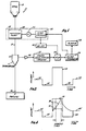
- Fig. 1 is a block diagram illustrating one form of infusion system constructed in accordance with the teachings of this invention.
- Fig. 2 is a plot of volume delivered by the infusion device versus time and illustrates a test pulse, two associated periods of reduced infusion rates, and regions of a normal delivery pattern.
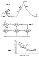
- Fig. 3 is a plot showing one pressure wave response indicative of the flowable material being properly supplied to the vessel of a patient and a second pressure wave response indicative of infiltration.
- Fig. 4 shows the two pressure wave responses of Fig. 3 in somewhat idealized form superimposed on the pump delivery plot of Fig. 2.
- Fig. 5 is a flow chart showing one way that the flow rate during a test pulse can be selected as a function of selected infusion rate.
- Fig. 6 is a plot of multiplying factor versus infusion rate.
- Fig. l shows an infusion system ll which comprises a source l3 of a parenteral fluid, an infusion device l5 for delivering the parenteral fluid through conduit means l7 to a patient. The conduit means l7 may comprise flexible tubing or other flow channels for supplying the parenteral fluid to the patient. The conduit means terminates in a needle l8, such as an I.V. needle, which is adapted to be inserted into a vessel of the patient's vascular system so that the open distal end of the needle communicates with the interior of the vessel. In this embodiment, the needle l8 is inserted into a vein. If the open distal end of the needle communicates with tissue, as when the needle is forced completely through the vessel wall, infiltration has occurred.
- The infusion device l5 may be any infusion device which is controllable to produce a test pulse l9 (Fig. 2) and, as such, may include an infusion pump, a controller, syringe or the like. In this embodiment, the infusion device l5 includes a stepping motor 2l for driving the pump and
pump controls 22 for controlling the stepping motor. Thepump 20 is a positive displacement pump, and accordingly, its output can be controlled by controlling the speed of the motor 2l. The pump controls 22 control the motor speed as described more fully hereinbelow to provide the infusion device with the desired output. - In a preferred construction, the infusion device 15 is a peristaltic pump Such an infusion pump has a
normal delivery pattern 25 which is essentially constant as shown by the flat portions of the pump delivery curve of Fig. 2. This is the result of accelerating through the deadband of the peristaltic pump. The curve of Fig. 2 is somewhat idealized in that the preferred infusion pump provides periodic short spikes and valleys of exceedingly short duration; however, these are sufficiently insignificant so that the normal delivery pattern of the pump can be considered as essentially constant. - The pump controls 22 periodically, and/or on demand, increase the speed of the stepping
motor 21 to cause theinfusion pump 20 to provide thetest pulse 19 which, in the illustrated embodiment of Fig. 2, is in the form of an essentially square wave having a duration of approximately four seconds. As described more fully hereinbelow with reference to Figs. 5 and 6, the infusion rate, and hence the volume delivered, during the test pulse preferably varies with the selected infusion rate for the infusion device 15. However, the duration of thetest pulse 19 may be constant for all selected infusion rates. Selection of the infusion rate also results in selection of the associated flow rate for thetest pulse 19. In this regard, the pump controls 22, as is common for infusion devices of this type, are programmable to enable the attendant to select or punch in a desired or selected infusion rate. - The pump controls 22 reduce the speed of the stepping motor 2l just before and just after each test pulse l9 to cause the
infusion pump 20 to provideinfusion valleys valleys valleys valleys normal delivery pattern 25. For example, each of thevalleys - The presence of the test pulse l9 in the conduit means l7 creates a pressure wave response which has different characteristics depending upon whether or not the flowable material is being improperly supplied by the conduit means l7 to the patient. Fig. 3 shows examples of pressure wave responses 3l and 33 which indicate in-the-vessel and infiltration conditions, respectively. Although the pressure wave responses 3l and 33 are both shown in Fig. 3, they are not in scale in relation to each other.
- The pressure provided by the pressure wave response 3l rises rapidly and almost instantaneously along a rising
edge 35 and decays at about the same rate as represented by a fallingedge 37. In between theedges short duration valley 39 which is representative of the deadband of the peristaltic pump being employed. In this regard, the pressure wave response 3l was generated by a peristaltic pump having a deadband and operating at about 350 cc's per hour, which is a high-delivery rate. If a peristaltic pump which accelerates through the deadband were employed, the duration and magnitude of thevalley 39 would be greatly reduced. For this reason, it is preferred to utilize a peristaltic pump which does accelerate through the deadband so that anyvalley 39 would be of substantially less magnitude and duration than illustrated in Fig. 3. However, the pressure wave response 3l is essentially a square wave if thevalley 39 is ignored. With the open distal end of the needle l8 of the conduit means l7 properly communicating with the interior of the vessel of the patient's cardiovascular system, the pressure wave response 3l is simply the result of forcing the additional flowable material into the fluid carried by the vessel. For example, for an infusion rate of 5 cc/hour, the pressure wave response 3l may rise about 5 mm Hg above a base line. - When infiltration occurs, the open distal end of the needle l8 is out of the interior of the vessel and communicates with tissue. As a result, the pressure wave response 33 is created in the conduit means l7. Specifically, the pressure wave response 33 rises along a rising edge 43 and falls along a falling
edge 45 with both the rise time and fall time being much greater than for the pressure wave response 3l. In addition, the pressure wave response 33 has amaximum pressure 47 which is much higher than the maximum pressure of the pressure wave response 3l. For example, for an infusion rate of 5 cc/hour, the pressure wave response 33 may rise about 20 mm Hg above abaseline 49. The rising edge has a discontinuity 48 which is the result of using a peristaltic infusion pump to generate the pressure wave response 33 which did not accelerate through the deadband and, therefore, did not have an essentially constant delivery rate. - The pressure of the parenteral fluid in the conduit means l7 can be monitored in various different ways, such as by a pressure transducer 5l which provides an electronic analog pressure signal which is related to the pressure in the conduit means l7. This pressure signal can be processed in a variety of different ways to determine if the pressure wave response 3l is present. In this regard, any of a variety of different characteristics of the pressure wave response can be used to determine which of the two pressure wave responses is present in response to the test pulse l9. However, whichever characteristic is selected, the same characteristic may be used regardless of the infusion rate which the infusion device l5 is programmed to deliver.
- Preferably, the rate of change of a portion of the pressure wave response is used to detect infiltration, and this can be best understood with reference to Fig. 4. Fig. 4 shows somewhat idealized pressure wave responses 3l and 33, which would be expected when using an infusion pump with an essentially constant output, superimposed on the delivery curve of the infusion device l5. Of course, the pressure wave responses 3l and 33 would not occur simultaneously as suggested by Fig. 4. As shown in Fig. 4, the portions of the pressure wave responses 3l and 33 which occur during a sample time are processed to determine which of the pressure wave responses is present. For example, during the sample time shown in Fig. 4, the pressure change along the pressure wave response 3l is essentially zero, whereas the pressure change from the beginning to the end of the sample time of the pressure wave response 33 is rather substantial. Accordingly, by determining the pressure change from the beginning to the end of the sample time and comparing this to a threshold magnitude, a decision can be made as to whether or not the pressure wave response 3l is present. The sample time may begin, for example, one second after the initiation of the test pulse and terminate, for example, one-half second before the end of the test pulse l9.
- The change in pressure of the pressure wave response from the beginning to the end of the sample time can be determined in various ways, such as by integrating the pressure signal from the transducer 5l during the sample time and comparing the integral with a threshold magnitude in a comparator. However, in this embodiment, the pressure signal from the transducer 5l is amplified by an amplifier 53, conditioned in signal conditioning circuitry 55 and sampled in an analog-to-digital converter (A/D converter) 57 which provides the samples to a
microprocessor 59. The signal conditioning circuitry 55 is conventional and is provided for the purpose of adjusting or compensating for various variables, such as temperature. Of course, if these variables are not considered significant, the signal conditioning circuitry 55 can be eliminated. - The samples of the pressure signal from the transducer 5l may be taken continuously or taken only during the sample time. In the former case, the
microprocessor 59 is used to separate the samples taken during the sample time from those which are not. However, in this embodiment, the A/D converter 57 samples the pressure signal only during the sample time and provides the samples in a digital format to themicroprocessor 59. The A/D converter 57 can be caused to sample the pressure signal during the sample time by transmitting a signal from the pump controls 22 to delay electronics 6l at the same instant that the pump controls 22 command the stepping motor 2l to reduce its speed to initiate thevalley 27 which precedes the test pulse l9. The delay electronics 6l transmits this signal to the A/D converter 57 after a predetermined time delay which may be, for example, 9 seconds when thevalley 27 is 8 seconds in duration and the test pulse l9 is 4 seconds in duration. This signal initiates operation of the A/D converter 57 for a predetermined time equal to the sample time so that samples of the pressure wave response are fed to themicroprocessor 59 during the sample time. - The sampling frequency of the A/
D converter 57 is preferably higher than the sampling frequency required for detecting infiltration. For example, if infiltration detection requires about one sample per second, samples may be taken at, for example, 5 samples per second. The 5 samples can then be combined in any of a variety of ways to produce an overall sample value for each second by themicroprocessor 59. In any event, themicroprocessor 59 ascertains the change in pressure from the beginning to the end of the sample time and compares the pressure change to a threshold magnitude of, for example, 8 mm Hg to determine if infiltration has occurred. If this pressure change exceeds 8 mm Hg, infiltration is detected. The threshold magnitude may be constant for all flow rates. - If the
microprocessor 59 detects infiltration, it may initiate various remedial action. For example, it may provide a signal to an alarm 63 which provides an audio and/or visual alarm, and/or it may discontinue operation of the infusion device l5 by sending a stop signal to the pump controls to bring about discontinuing the transmission of signals to the stepping motor 2l. - Another function of the pump controls 22 is to determine the infusion or flow rate during the test pulse l9. The infusion rate during the test pulse l9 is preferably a function of the selected infusion rate and may be expressed as a multiple of the selected infusion rate. Thus, as the attendant selects or punches in the selected infusion rate, the flow rate during the test pulse is simultaneously determined as a multiple of the selected infusion rate by software or logic circuitry in the pump controls 22. Because the
valleys - The pump controls 22 can, of course, be programmed to vary infusion rate during the test pulse in any desired manner as a function of selected infusion rate. However, preferably, the infusion rate during the test pulse l9 equals the selected infusion rate times a multiplying factor, Cp. The multiplying factor Cp and the ratio of test pulse flow rate to selected infusion rate reduce as selected infusion rate increases as shown by way of example in Fig. 6. For example, for a relatively low selected infusion rate, such as 2 cc's per hour, Cp may equal 7. In other words, the infusion rate during the test pulse would be 7 times the infusion rate occurring during the
normal delivery pattern 25 in Fig. 2. For a relatively high infusion rate, such as l00 cc's per hour, Cp may equal a much lower number, such as l.28. As shown in Fig. 6, the multiplying factor may be reduced along a smoothcontinuous curve 57 or in stepwise fashion along acurve 59 which is shown in dashed lines. - The presence of the
valleys valleys - Although the pump controls 22 can implement virtually any desired equation for expressing Cp as a function of the infusion rate, one suitable equation is as follows:

where
P₁ is the pressure at the end of the sample time;
P₂ is the pressure at the beginning of the sample time; and
R is the selected infusion rate in cc/hour. - This equation could be implemented, for example, in several stages or steps by assuming values of P₁ - P₂ for several different groups of flow rates as follows:
P₁ - P₂ Selected Infusion Rate 12 Up to 5 cc's per hour. 20 6 to 12 cc's per hour. 28 over 12 cc's per hour.
Of course, any number of steps can be used, and the three steps identified above are purely illustrative. This can be implemented, for example, with software as shown in the flow chart of Fig. 5 to obtain three different multiplying factors Cp1 , Cp2 and Cp3 (Figs. 5 and 6) which are applicable to the associated selected infusion rates (R). - Although an exemplary embodiment of the invention has been shown and described, many changes, modifications and substitutions may be made by one having ordinary skill in the art without necessarily departing from the scope of this invention as defined in the claims.
Claims (13)
- An infusion system for infusing a flowable material into a patient: comprising an infusion device (15) including means for delivering the flowable material in a normal delivery pattern;
conduit means (17) for conducting the flowable material from the infusion device (15) to the patient; and
means for monitoring pressure in the conduit means (17) for detecting if the flowable material is being improperly supplied by the conduit means (17) to the patient;
characterised in that the infusion device (15) also includes means for delivering a test pulse of the flowable material, said test pulse being different from the normal delivery pattern, said test pulse creating a pressure wave response in the conduit means (17), and wherein said means for monitoring the pressure in the conduit means (17) are means responsive to the pressure wave response created by said test pulse. - An infusion system according to claim 1 wherein said normal delivery pattern has an essentially constant flow rate.
- An infusion system according to claim 1 or claim 2 wherein said delivering means includes means for delivering a reduced flow rate of the flowable material adjacent the test pulse with said reduced flow rate being less than the flow rate during the normal delivery pattern to at least partially compensate for increased flow rate of the flowable material provided during the test pulse.
- An infusion system according to claim 3 wherein said reduced flow rate delivery means provides said reduced flow rates on opposite sides of the test pulse.
- An infusion system according to anyone of claims 1 to 3 wherein said delivering means includes means for enabling the infusion device (15) to selectively deliver the flowable material at different selected flow rates and means responsive to the selected rate for controlling the flow rate of the flowable material provided during the test pulse.
- An infusion system according to claim 5 wherein said controlling means decreases the ratio of test pulse flow rate to selected flow rate for increased selected flow rates.
- An infusion system according to anyone of claims 1 to 6 wherein said delivering means includes means for selectively causing the infusion device (15) to initiate a test pulse on demand.
- An infusion system according to anyone of claims 1 to 7 wherein said detecting means includes means responsive to the rate of change of at least a portion of the pressure wave response in the conduit means for detecting if the flowable material is being improperly supplied by the conduit means (17) to the patient.
- An infusion system according to anyone of claims 1 to 8 wherein said detecting means detects the improper supply of the flowable material when the pressure change of at least a portion of the pressure wave response exceeds a predetermined magnitude.
- An infusion system according to anyone of claims 1 to 9 wherein said detecting means includes a pressure transducer (51) for providing a pressure signal which is related to the pressure in the conduit means, means (57) for sampling said pressure signal at least during a sample time which occurs at least partially during the pressure wave response to provide a plurality of digital samples and means responsive to the samples obtained during said sample time for detecting if the flowable material is being improperly supplied by the conduit means to the patient.
- An infusion system according to anyone of claims 1 to 10 wherein the infusion device is capable of operation at a plurality of infusion rates and said detecting means is reponsive at any infusion rate of the infusion device (15) to the change in pressure of the same portion of the pressure wave response during a predetermined period for detecting if supply of the flowable material is being properly supplied to the patient.
- An apparatus for use with an infusion device (15) which infuses flowable material at any of a plurality of selected infusion rates through conduit means (17) to a patient, the delivery of the flowable material from the infusion device (15) including a pulse which provides a pressure wave response in the conduit means whose characteristics change depending upon whether or not the conduit means (17) is properly supplying the flowable material to the patient, said apparatus comprising:
a pressure transducer (51) for providing a pressure signal which is related to at least a portion of the pressure wave response;
infiltration detection means responsive to the same characteristic of the pressure wave response as represented by the pressure signal for detecting infiltration regardless of the infusion rate; and
means (63) responsive to the detecting means for indictating and/or providing remedial action if the flowable material is not being properly supplied to the patient. - An apparatus as defined in claim 12 wherein said characteristic is the change in pressure of the same portion of the pressure wave response during a predetermined period.
Applications Claiming Priority (2)
| Application Number | Priority Date | Filing Date | Title |
|---|---|---|---|
| US804675 | 1985-12-04 | ||
| US06/804,675 US4648869A (en) | 1985-12-04 | 1985-12-04 | Automatic infiltration detection system and method |
Publications (2)
| Publication Number | Publication Date |
|---|---|
| EP0232599A1 EP0232599A1 (en) | 1987-08-19 |
| EP0232599B1 true EP0232599B1 (en) | 1991-10-09 |
Family
ID=25189548
Family Applications (1)
| Application Number | Title | Priority Date | Filing Date |
|---|---|---|---|
| EP86309164A Expired EP0232599B1 (en) | 1985-12-04 | 1986-11-25 | Automatic infiltration detection system |
Country Status (5)
| Country | Link |
|---|---|
| US (1) | US4648869A (en) |
| EP (1) | EP0232599B1 (en) |
| JP (1) | JPH0673548B2 (en) |
| CA (1) | CA1272794A (en) |
| DE (1) | DE3681911D1 (en) |
Cited By (2)
| Publication number | Priority date | Publication date | Assignee | Title |
|---|---|---|---|---|
| US9383288B2 (en) | 2008-06-26 | 2016-07-05 | Gambro Lundia Ab | Method and device for processing a time-dependent measurement signal |
| US9433356B2 (en) | 2009-06-26 | 2016-09-06 | Gambro Lundia Ab | Devices, a computer program product and a method for data extraction |
Families Citing this family (114)
| Publication number | Priority date | Publication date | Assignee | Title |
|---|---|---|---|---|
| US4778451A (en) * | 1986-03-04 | 1988-10-18 | Kamen Dean L | Flow control system using boyle's law |
| EP0248632B1 (en) * | 1986-06-06 | 1992-04-15 | Ivac Corporation | Intravenous fluid flow monitor |
| US5527274A (en) * | 1986-06-09 | 1996-06-18 | Development Collaborative Corporation | Catheter for chemical contact dissolution of gallstones |
| US4882575A (en) * | 1987-01-28 | 1989-11-21 | Sharp Kabushiki Kaisha | Monitor for blocked condition in tube for fluid infusion pump |
| FR2615397B1 (en) * | 1987-05-20 | 1990-05-04 | Marseille Assistance Publique | CONTINUOUS, CONTINUOUS PRESSURE INFLATION DEVICE OF TISSUE EXPANSION BALLOONS |
| US4925444A (en) * | 1987-08-07 | 1990-05-15 | Baxter Travenol Laboratories, Inc. | Closed multi-fluid delivery system and method |
| US4846792A (en) * | 1988-03-08 | 1989-07-11 | Baxter International Inc. | Automatic infiltration detection system and method |
| US4979940A (en) * | 1988-03-08 | 1990-12-25 | Baxter International Inc. | Infusion system, methodology, and algorithm for identifying patient-induced pressure artifacts |
| US5026348A (en) * | 1988-06-06 | 1991-06-25 | The General Hospital Corporation | Apparatus and method for the detection of IV catheter obstruction and extravasation |
| US4959050A (en) * | 1988-09-26 | 1990-09-25 | Baxter International Inc. | In-line infiltration detection apparatus and method |
| US4943279A (en) * | 1988-09-30 | 1990-07-24 | C. R. Bard, Inc. | Medical pump with infusion controlled by a detachable coded label |
| JPH0511872Y2 (en) * | 1988-11-30 | 1993-03-25 | ||
| US5087245A (en) * | 1989-03-13 | 1992-02-11 | Ivac Corporation | System and method for detecting abnormalities in intravascular infusion |
| JPH061151Y2 (en) * | 1989-04-28 | 1994-01-12 | シャープ株式会社 | Tube internal pressure display device for infusion pump |
| US5096385A (en) * | 1989-11-08 | 1992-03-17 | Ivac Corporation | Method and system for upstream occlusion detection |
| US5018945A (en) * | 1989-12-14 | 1991-05-28 | Baxter International Inc. | Accurate peristaltic pump |
| WO1992022337A1 (en) * | 1991-06-10 | 1992-12-23 | Baxter International Inc. | Intravenous metering monitoring device |
| WO1995005864A1 (en) * | 1993-08-27 | 1995-03-02 | Government Of The United States Of America, Represented By The Secretary Of The Department Of Health And Human Services | Convection-enhanced drug delivery |
| US5423743A (en) * | 1993-09-17 | 1995-06-13 | Ivac Corporation | Cannula position detection |
| US5947910A (en) | 1994-01-14 | 1999-09-07 | E-Z-Em, Inc. | Extravasation detection technique |
| USRE38695E1 (en) | 1994-01-14 | 2005-02-08 | E-Z-Em, Inc. | Extravasation detection electrode patch |
| US5651775A (en) | 1995-07-12 | 1997-07-29 | Walker; Richard Bradley | Medication delivery and monitoring system and methods |
| SE508374C2 (en) * | 1995-09-12 | 1998-09-28 | Gambro Med Tech Ab | Method and apparatus for detecting the condition of a blood vessel access |
| US5772634A (en) * | 1995-10-06 | 1998-06-30 | Zimmer, Inc. | Device for limiting distention fluid pressure during hysteroscopy |
| US5915282A (en) * | 1995-12-14 | 1999-06-22 | Abbott Laboratories | Fluid handler and method of handling a fluid |
| US5954668A (en) | 1996-06-14 | 1999-09-21 | Medrad, Inc. | Extravasation detector using microwave radiometry |
| US6142008A (en) * | 1998-06-12 | 2000-11-07 | Abbott Laboratories | Air bubble sensor |
| US6176847B1 (en) * | 1999-05-14 | 2001-01-23 | Circon Corporation | Surgical irrigation system incorporating flow sensor device |
| US6408204B1 (en) | 1999-07-28 | 2002-06-18 | Medrad, Inc. | Apparatuses and methods for extravasation detection |
| US7047058B1 (en) | 2001-02-06 | 2006-05-16 | Medrad, Inc. | Apparatuses, systems and methods for extravasation detection |
| US7147615B2 (en) | 2001-06-22 | 2006-12-12 | Baxter International Inc. | Needle dislodgement detection |
| EP1647306B1 (en) * | 2001-07-26 | 2012-03-21 | Medrad, Inc. | Electromagnetic sensors for biological tissue applications |
| WO2003009753A2 (en) * | 2001-07-26 | 2003-02-06 | Chad Bouton | Detection of fluids in tissue |
| US20040073117A1 (en) * | 2002-02-14 | 2004-04-15 | Schwarz Karl Q. | Method and system for delivering contrast agent |
| US20040254513A1 (en) * | 2002-04-10 | 2004-12-16 | Sherwin Shang | Conductive polymer materials and applications thereof including monitoring and providing effective therapy |
| US7138088B2 (en) * | 2002-04-10 | 2006-11-21 | Baxter International Inc. | Access disconnection system and methods |
| US7052480B2 (en) * | 2002-04-10 | 2006-05-30 | Baxter International Inc. | Access disconnection systems and methods |
| US7022098B2 (en) | 2002-04-10 | 2006-04-04 | Baxter International Inc. | Access disconnection systems and methods |
| US10155082B2 (en) | 2002-04-10 | 2018-12-18 | Baxter International Inc. | Enhanced signal detection for access disconnection systems |
| US8029454B2 (en) * | 2003-11-05 | 2011-10-04 | Baxter International Inc. | High convection home hemodialysis/hemofiltration and sorbent system |
| US10463778B2 (en) | 2007-02-09 | 2019-11-05 | Baxter International Inc. | Blood treatment machine having electrical heartbeat analysis |
| US8376978B2 (en) * | 2007-02-09 | 2013-02-19 | Baxter International Inc. | Optical access disconnection systems and methods |
| US8152751B2 (en) * | 2007-02-09 | 2012-04-10 | Baxter International Inc. | Acoustic access disconnection systems and methods |
| US8197431B2 (en) * | 2007-09-21 | 2012-06-12 | Baxter International Inc. | Acoustic access disconnect detection system |
| US9026370B2 (en) | 2007-12-18 | 2015-05-05 | Hospira, Inc. | User interface improvements for medical devices |
| US7880624B2 (en) * | 2008-01-08 | 2011-02-01 | Baxter International Inc. | System and method for detecting occlusion using flow sensor output |
| US9138536B2 (en) | 2008-04-01 | 2015-09-22 | Gambro Lundia Ab | Apparatus and a method for monitoring a vascular access |
| US8114043B2 (en) | 2008-07-25 | 2012-02-14 | Baxter International Inc. | Electromagnetic induction access disconnect sensor |
| US8192388B2 (en) * | 2008-07-25 | 2012-06-05 | Baxter International Inc. | System and method for detecting access disconnection |
| DE102009007806B4 (en) | 2009-02-06 | 2014-06-05 | Fresenius Medical Care Deutschland Gmbh | Device for vibrational excitation of at least a portion of a vascular access device for monitoring thereof |
| US9480455B2 (en) | 2009-06-18 | 2016-11-01 | Quanta Fluid Solutions, Ltd. | Vascular access monitoring device |
| US9592029B2 (en) | 2009-06-18 | 2017-03-14 | Quanta Fluid Solutions Ltd. | Vascular access monitoring device |
| US10980431B2 (en) | 2009-12-28 | 2021-04-20 | Gambro Lundia Ab | Apparatus and method for prediction of rapid symptomatic blood pressure decrease |
| US9151646B2 (en) | 2011-12-21 | 2015-10-06 | Deka Products Limited Partnership | System, method, and apparatus for monitoring, regulating, or controlling fluid flow |
| WO2013028497A1 (en) | 2011-08-19 | 2013-02-28 | Hospira, Inc. | Systems and methods for a graphical interface including a graphical representation of medical data |
| US10722136B2 (en) | 2011-09-02 | 2020-07-28 | Battelle Memorial Institute | Wireless and power-source-free extravasation and infiltration detection sensor |
| US10022498B2 (en) | 2011-12-16 | 2018-07-17 | Icu Medical, Inc. | System for monitoring and delivering medication to a patient and method of using the same to minimize the risks associated with automated therapy |
| US9724466B2 (en) | 2011-12-21 | 2017-08-08 | Deka Products Limited Partnership | Flow meter |
| US9435455B2 (en) | 2011-12-21 | 2016-09-06 | Deka Products Limited Partnership | System, method, and apparatus for monitoring, regulating, or controlling fluid flow |
| US10563681B2 (en) | 2011-12-21 | 2020-02-18 | Deka Products Limited Partnership | System, method, and apparatus for clamping |
| US10488848B2 (en) | 2011-12-21 | 2019-11-26 | Deka Products Limited Partnership | System, method, and apparatus for monitoring, regulating, or controlling fluid flow |
| US10088346B2 (en) | 2011-12-21 | 2018-10-02 | Deka Products Limited Partnership | System, method, and apparatus for monitoring, regulating, or controlling fluid flow |
| US9856990B2 (en) | 2011-12-21 | 2018-01-02 | Deka Products Limited Partnership | Flow metering using a difference image for liquid parameter estimation |
| US9372486B2 (en) | 2011-12-21 | 2016-06-21 | Deka Products Limited Partnership | System, method, and apparatus for monitoring, regulating, or controlling fluid flow |
| US9746094B2 (en) | 2011-12-21 | 2017-08-29 | Deka Products Limited Partnership | Flow meter having a background pattern with first and second portions |
| US9746093B2 (en) | 2011-12-21 | 2017-08-29 | Deka Products Limited Partnership | Flow meter and related system and apparatus |
| EP2830687B1 (en) | 2012-03-30 | 2019-07-24 | ICU Medical, Inc. | Air detection system and method for detecting air in a pump of an infusion system |
| US8700133B2 (en) | 2012-06-18 | 2014-04-15 | Smart Iv Llc | Apparatus and method for monitoring catheter insertion |
| US9597482B2 (en) | 2012-06-18 | 2017-03-21 | Smart Iv Llc | Apparatus and method for monitoring catheter insertion |
| CA3089257C (en) | 2012-07-31 | 2023-07-25 | Icu Medical, Inc. | Patient care system for critical medications |
| US9759343B2 (en) | 2012-12-21 | 2017-09-12 | Deka Products Limited Partnership | Flow meter using a dynamic background image |
| CA2899720C (en) | 2013-03-20 | 2021-04-20 | Gambro Lundia Ab | Monitoring of cardiac arrest in a patient connected to an extracorporeal blood processing apparatus |
| GB201305755D0 (en) | 2013-03-28 | 2013-05-15 | Quanta Fluid Solutions Ltd | Re-Use of a Hemodialysis Cartridge |
| CA2913421C (en) | 2013-05-24 | 2022-02-15 | Hospira, Inc. | Multi-sensor infusion system for detecting air or an occlusion in the infusion system |
| AU2014274122A1 (en) | 2013-05-29 | 2016-01-21 | Icu Medical, Inc. | Infusion system and method of use which prevents over-saturation of an analog-to-digital converter |
| ES2838450T3 (en) | 2013-05-29 | 2021-07-02 | Icu Medical Inc | Infusion set that uses one or more sensors and additional information to make an air determination relative to the infusion set |
| GB201314512D0 (en) | 2013-08-14 | 2013-09-25 | Quanta Fluid Solutions Ltd | Dual Haemodialysis and Haemodiafiltration blood treatment device |
| USD745661S1 (en) | 2013-11-06 | 2015-12-15 | Deka Products Limited Partnership | Apparatus to control fluid flow through a tube |
| USD751690S1 (en) | 2013-11-06 | 2016-03-15 | Deka Products Limited Partnership | Apparatus to control fluid flow through a tube |
| USD752209S1 (en) | 2013-11-06 | 2016-03-22 | Deka Products Limited Partnership | Apparatus to control fluid flow through a tube |
| USD749206S1 (en) | 2013-11-06 | 2016-02-09 | Deka Products Limited Partnership | Apparatus to control fluid flow through a tube |
| USD751689S1 (en) | 2013-11-06 | 2016-03-15 | Deka Products Limited Partnership | Apparatus to control fluid flow through a tube |
| EP3110474B1 (en) | 2014-02-28 | 2019-12-18 | ICU Medical, Inc. | Infusion system and method which utilizes dual wavelength optical air-in-line detection |
| JP2017517302A (en) | 2014-05-29 | 2017-06-29 | ホスピーラ インコーポレイテッド | Infusion system and pump with configurable closed loop delivery rate catchup |
| GB201409796D0 (en) | 2014-06-02 | 2014-07-16 | Quanta Fluid Solutions Ltd | Method of heat sanitization of a haemodialysis water circuit using a calculated dose |
| US10531799B2 (en) | 2014-09-12 | 2020-01-14 | Vanderbilt University | Intravenous access device detecting intravenous infiltration and in-vein placement |
| US11344668B2 (en) | 2014-12-19 | 2022-05-31 | Icu Medical, Inc. | Infusion system with concurrent TPN/insulin infusion |
| ES2901790T3 (en) * | 2015-02-03 | 2022-03-23 | Univ Vanderbilt | Intravenous access device that detects intravenous infiltration and placement in the vein |
| US10850024B2 (en) | 2015-03-02 | 2020-12-01 | Icu Medical, Inc. | Infusion system, device, and method having advanced infusion features |
| US10413654B2 (en) | 2015-12-22 | 2019-09-17 | Baxter International Inc. | Access disconnection system and method using signal metrics |
| GB201523104D0 (en) | 2015-12-30 | 2016-02-10 | Quanta Fluid Solutions Ltd | Dialysis machine |
| USD905848S1 (en) | 2016-01-28 | 2020-12-22 | Deka Products Limited Partnership | Apparatus to control fluid flow through a tube |
| EP4335471A3 (en) | 2016-01-28 | 2024-08-21 | DEKA Products Limited Partnership | Apparatus for monitoring, regulating, or controlling fluid flow |
| GB2547214A (en) | 2016-02-10 | 2017-08-16 | Quanta Fluid Solutions Ltd | Membrane pump usage condition detection |
| EP3454922B1 (en) | 2016-05-13 | 2022-04-06 | ICU Medical, Inc. | Infusion pump system with common line auto flush |
| USD854145S1 (en) | 2016-05-25 | 2019-07-16 | Deka Products Limited Partnership | Apparatus to control fluid flow through a tube |
| AU2017277804B2 (en) | 2016-06-10 | 2022-05-26 | Icu Medical, Inc. | Acoustic flow sensor for continuous medication flow measurements and feedback control of infusion |
| CN106139301B (en) * | 2016-07-18 | 2019-08-13 | 丁松华 | A kind of nursing in operating room venous transfusion anti-intrusion device |
| GB201622119D0 (en) | 2016-12-23 | 2017-02-08 | Quanta Dialysis Tech Ltd | Improved valve leak detection system |
| GB201701740D0 (en) | 2017-02-02 | 2017-03-22 | Quanta Dialysis Tech Ltd | Phased convective operation |
| GB201705273D0 (en) | 2017-03-31 | 2017-05-17 | Quanta Dialysis Tech Ltd | Data storage amd exchange by medical device components |
| GB201710546D0 (en) | 2017-06-30 | 2017-08-16 | Quanta Dialysis Tech Ltd | Dialysis systems, devices and methods |
| USD907211S1 (en) | 2017-09-28 | 2021-01-05 | Quanta Dialysis Technologies Ltd. | Dialysis machine |
| US10089055B1 (en) | 2017-12-27 | 2018-10-02 | Icu Medical, Inc. | Synchronized display of screen content on networked devices |
| GB2584335A (en) | 2019-05-31 | 2020-12-02 | Quanta Dialysis Technologies Ltd | Source container connector |
| USD964563S1 (en) | 2019-07-26 | 2022-09-20 | Deka Products Limited Partnership | Medical flow clamp |
| WO2021021596A1 (en) | 2019-07-26 | 2021-02-04 | Deka Products Limited Partnership | Apparatus for monitoring, regulating, or controlling fluid flow |
| CN110639083A (en) * | 2019-10-31 | 2020-01-03 | 滨州职业学院 | Venous transfusion anti-seepage device for operating room nursing |
| US11278671B2 (en) | 2019-12-04 | 2022-03-22 | Icu Medical, Inc. | Infusion pump with safety sequence keypad |
| WO2022020184A1 (en) | 2020-07-21 | 2022-01-27 | Icu Medical, Inc. | Fluid transfer devices and methods of use |
| US11135360B1 (en) | 2020-12-07 | 2021-10-05 | Icu Medical, Inc. | Concurrent infusion with common line auto flush |
| US12599716B2 (en) | 2021-10-12 | 2026-04-14 | Icu Medical, Inc. | Intravenous infusion pump with cassette insertion and pump control user interface |
| USD1091564S1 (en) | 2021-10-13 | 2025-09-02 | Icu Medical, Inc. | Display screen or portion thereof with graphical user interface for a medical device |
| AU2022407460A1 (en) | 2021-12-10 | 2024-06-27 | Icu Medical, Inc. | Medical fluid compounding systems with coordinated flow control |
Family Cites Families (16)
| Publication number | Priority date | Publication date | Assignee | Title |
|---|---|---|---|---|
| US3690318A (en) * | 1970-04-16 | 1972-09-12 | Bourns Inc | Apparatus for parenteral fluid infusion provided with variable flow control means |
| US4273122A (en) * | 1976-11-12 | 1981-06-16 | Whitney Douglass G | Self contained powered injection system |
| US4192319A (en) * | 1977-09-30 | 1980-03-11 | Regents Of University Of California | Wick catheter pressure sensing probe and method of use |
| US4209023A (en) * | 1979-02-22 | 1980-06-24 | The Kendall Company | Tissue pressure measuring device |
| US4277227A (en) * | 1979-07-02 | 1981-07-07 | Imed Corporation | Apparatus for converting a pump to a controller |
| DE3018641C2 (en) * | 1980-05-16 | 1986-05-28 | Hans 8228 Freilassing Rodler | Automatic infusion pump |
| US4444546A (en) * | 1980-09-19 | 1984-04-24 | Oximetrix, Inc. | Occlusion detection apparatus and method |
| DE3035670A1 (en) * | 1980-09-22 | 1982-04-29 | Siemens AG, 1000 Berlin und 8000 München | DEVICE FOR INFUSING LIQUIDS IN HUMAN OR ANIMAL BODIES |
| US4423740A (en) * | 1981-03-30 | 1984-01-03 | Howmedica, Inc. | Slit catheter method for measuring interstitial pressure |
| US4474309A (en) * | 1981-10-22 | 1984-10-02 | Oximetrix, Inc. | Stepping motor control procedure for achieving variable rate, quasi-continuous fluid infusion |
| US4460355A (en) * | 1982-06-11 | 1984-07-17 | Ivac Corporation | Fluid pressure monitoring system |
| US4534756A (en) * | 1983-04-11 | 1985-08-13 | Ivac Corporation | Fault detection apparatus and method for parenteral infusion system |
| US4530696A (en) * | 1983-06-13 | 1985-07-23 | Institute Of Critical Care Medicine | Monitor for intravenous injection system for detecting occlusion and/or infiltration |
| US4468219A (en) * | 1983-12-20 | 1984-08-28 | International Business Machines Corporation | Pump flow rate compensation system |
| ATE37661T1 (en) * | 1984-04-14 | 1988-10-15 | Ferring Biotechnik | DEVICE FOR INTERMITTENT APPLICATION OF LIQUID MEDICATIONS. |
| US4551133A (en) * | 1984-04-16 | 1985-11-05 | American Hospital Supply Corporation | Patient controlled medication infusion system |
-
1985
- 1985-12-04 US US06/804,675 patent/US4648869A/en not_active Expired - Lifetime
-
1986
- 1986-11-19 CA CA000523360A patent/CA1272794A/en not_active Expired
- 1986-11-25 EP EP86309164A patent/EP0232599B1/en not_active Expired
- 1986-11-25 DE DE8686309164T patent/DE3681911D1/en not_active Expired - Lifetime
- 1986-12-03 JP JP61288652A patent/JPH0673548B2/en not_active Expired - Fee Related
Cited By (3)
| Publication number | Priority date | Publication date | Assignee | Title |
|---|---|---|---|---|
| US9383288B2 (en) | 2008-06-26 | 2016-07-05 | Gambro Lundia Ab | Method and device for processing a time-dependent measurement signal |
| US9442036B2 (en) | 2008-06-26 | 2016-09-13 | Gambro Lundia Ab | Methods and devices for monitoring the integrity of a fluid connection |
| US9433356B2 (en) | 2009-06-26 | 2016-09-06 | Gambro Lundia Ab | Devices, a computer program product and a method for data extraction |
Also Published As
| Publication number | Publication date |
|---|---|
| JPH0673548B2 (en) | 1994-09-21 |
| CA1272794A (en) | 1990-08-14 |
| EP0232599A1 (en) | 1987-08-19 |
| DE3681911D1 (en) | 1991-11-14 |
| JPS62137064A (en) | 1987-06-19 |
| US4648869A (en) | 1987-03-10 |
Similar Documents
| Publication | Publication Date | Title |
|---|---|---|
| US4648869A (en) | Automatic infiltration detection system and method | |
| EP0332330B1 (en) | Automatic infiltration detection system | |
| US4959050A (en) | In-line infiltration detection apparatus and method | |
| US4743228A (en) | Fluid flow monitoring method and system | |
| EP1736667B1 (en) | Detecting obstructions in enteral/parenteral feeding tubes | |
| EP0344842B1 (en) | Apparatus for withdrawing an optimum amount of blood per unit of time from a donor | |
| EP0248633B1 (en) | Detection of fluid flow faults in the parenteral administration of fluids | |
| US4898576A (en) | Intravenous fluid flow monitor | |
| EP0248632B1 (en) | Intravenous fluid flow monitor | |
| US7402154B2 (en) | Method for compensating for pressure differences across valves in cassette type IV pump | |
| EP0453523B1 (en) | Infusion system, methodology, and algorithm for identifying patient-induced pressure artifacts | |
| EP0328162B1 (en) | Fault detection apparatus for parenteral infusion system and method of detecting a fault in a parenteral infusion system | |
| CA2565271C (en) | Flow monitoring system for a flow control apparatus | |
| DE69619282T2 (en) | SYSTEM AND METHOD FOR PRESSURE MONITORING IN ENTERAL NUTRITION | |
| CA2876317C (en) | Method and apparatus for detection and management of air-in-line | |
| EP0387724A2 (en) | Apparatus and method for detecting abnormalities in intravascular infusion | |
| WO2002035979A3 (en) | Method and apparatus for blood withdrawal and infusion using a pressure controller | |
| KR20150064706A (en) | Injector for the injection of a fluid and method for the control of an injector |
Legal Events
| Date | Code | Title | Description |
|---|---|---|---|
| PUAI | Public reference made under article 153(3) epc to a published international application that has entered the european phase |
Free format text: ORIGINAL CODE: 0009012 |
|
| AK | Designated contracting states |
Kind code of ref document: A1 Designated state(s): DE FR GB |
|
| 17P | Request for examination filed |
Effective date: 19871007 |
|
| RAP1 | Party data changed (applicant data changed or rights of an application transferred) |
Owner name: BAXTER INTERNATIONAL INC. (A DELAWARE CORPORATION) |
|
| 17Q | First examination report despatched |
Effective date: 19890629 |
|
| GRAA | (expected) grant |
Free format text: ORIGINAL CODE: 0009210 |
|
| AK | Designated contracting states |
Kind code of ref document: B1 Designated state(s): DE FR GB |
|
| REF | Corresponds to: |
Ref document number: 3681911 Country of ref document: DE Date of ref document: 19911114 |
|
| ET | Fr: translation filed | ||
| PLBE | No opposition filed within time limit |
Free format text: ORIGINAL CODE: 0009261 |
|
| STAA | Information on the status of an ep patent application or granted ep patent |
Free format text: STATUS: NO OPPOSITION FILED WITHIN TIME LIMIT |
|
| 26N | No opposition filed | ||
| REG | Reference to a national code |
Ref country code: GB Ref legal event code: IF02 |
|
| PGFP | Annual fee paid to national office [announced via postgrant information from national office to epo] |
Ref country code: GB Payment date: 20031119 Year of fee payment: 18 Ref country code: FR Payment date: 20031119 Year of fee payment: 18 |
|
| PGFP | Annual fee paid to national office [announced via postgrant information from national office to epo] |
Ref country code: DE Payment date: 20031231 Year of fee payment: 18 |
|
| PG25 | Lapsed in a contracting state [announced via postgrant information from national office to epo] |
Ref country code: GB Free format text: LAPSE BECAUSE OF NON-PAYMENT OF DUE FEES Effective date: 20041125 |
|
| PG25 | Lapsed in a contracting state [announced via postgrant information from national office to epo] |
Ref country code: DE Free format text: LAPSE BECAUSE OF NON-PAYMENT OF DUE FEES Effective date: 20050601 |
|
| GBPC | Gb: european patent ceased through non-payment of renewal fee |
Effective date: 20041125 |
|
| PG25 | Lapsed in a contracting state [announced via postgrant information from national office to epo] |
Ref country code: FR Free format text: LAPSE BECAUSE OF NON-PAYMENT OF DUE FEES Effective date: 20050729 |
|
| REG | Reference to a national code |
Ref country code: FR Ref legal event code: ST |