EP0232517A2 - Pipette - Google Patents
Pipette Download PDFInfo
- Publication number
- EP0232517A2 EP0232517A2 EP86117244A EP86117244A EP0232517A2 EP 0232517 A2 EP0232517 A2 EP 0232517A2 EP 86117244 A EP86117244 A EP 86117244A EP 86117244 A EP86117244 A EP 86117244A EP 0232517 A2 EP0232517 A2 EP 0232517A2
- Authority
- EP
- European Patent Office
- Prior art keywords
- pipette
- piston
- outer sleeve
- microcapillary
- pressure
- Prior art date
- Legal status (The legal status is an assumption and is not a legal conclusion. Google has not performed a legal analysis and makes no representation as to the accuracy of the status listed.)
- Granted
Links
Images
Classifications
-
- B—PERFORMING OPERATIONS; TRANSPORTING
- B01—PHYSICAL OR CHEMICAL PROCESSES OR APPARATUS IN GENERAL
- B01L—CHEMICAL OR PHYSICAL LABORATORY APPARATUS FOR GENERAL USE
- B01L3/00—Containers or dishes for laboratory use, e.g. laboratory glassware; Droppers
- B01L3/02—Burettes; Pipettes
- B01L3/021—Pipettes, i.e. with only one conduit for withdrawing and redistributing liquids
Definitions
- the invention relates to a pipette according to the preamble of patent claim 1.
- Such a pipette is known from DE-PS 28 51 532.
- the known pipette has an elastic bellows. The bellows stroke is limited by predetermined stops.
- the liquid to be sucked up is first sucked through a suction stroke into the suction tip attached to the housing of the pipette.
- the liquid is then expelled from the pipette by means of a pressure stroke.
- the known pipette is therefore not suitable for taking up liquid in self-absorbing microcapillaries in which, due to the capillary action of liquids, the liquid to be sucked up is taken up by a microcapillary, without an internal pressure being reduced compared to the external pressure, for example by a suction stroke got to.
- the object of the invention is therefore to provide a pipette of the type specified at the outset which is suitable for holding liquid in self-absorbing microcapillaries and which is simple and reliable to use.
- this object is achieved in that a pressure compensation opening is provided in the bellows.
- a pressure equalization can therefore take place during the suction process.
- no excess pressure can build up in the interior of the capillary, which would hinder further liquid absorption in the microcapillary.
- the operator can limit himself to observing the intake process; further measures on your part are not required.
- Even after completion of the liquid intake the amount of liquid once taken up remains reliably in the microcapillary without the operator having to do anything.
- the liquid can be removed from the microcapillary by the operator closing the pressure compensation opening and executes a pressure stroke. The liquid is then pressed out by the excess pressure in the capillary.
- the pipette has a holder in which a microcapillary is held in a frictionally engaged manner.
- the receptacle can consist of a rubber grommet, which gives the microcapillary a secure and tight hold in a particularly simple manner. If the receptacle consists of two support surfaces arranged at a distance from one another, a particularly secure holding of the capillary is ensured.
- part of the outer sleeve of the pipette is formed by an adapter for the microcapillary, it is possible to adapt the pipette according to the invention to microcapillaries of different dimensions, in particular different diameters, in a quick and simple manner by changing the adapter.
- the capillary is transparent, the level of the liquid in the capillary can be observed. By dimensioning the capillary, predetermined amounts of the liquid to be sucked up can be measured simply and precisely. Because the outer sleeve or the adapter is transparent in the area of the capillary, the liquid to be sucked up can be observed and / or measured over a greater or possibly over the entire length of the capillary.
- the bellows If the bellows is connected to a push pin protruding from the outer sleeve of the pipette, it can be actuated in a simple manner by the operator. If the pressure equalization opening is on the pressure surface of the pressure pin, which is hollow and airtightly connected to the bellows, this pressure equalization opening can be easily made by placing a Fingers, in particular the operator's finger actuating the pressure pin, are closed.
- the bellows in an advantageous embodiment of the invention has a spring action in the direction of its position with a larger volume, the pipette is automatically moved back into its initial position after the liquid has been ejected. This effect can be enhanced by providing the bellows with a compression spring.
- bactericidal substances or toxic reagents are to be treated with a pipette, it must be ensured that the operator does not come into contact with such substances.
- liquid sensors in particular microcapillaries, are used for such work, which have to be inserted manually into the pipette.
- the receptacle consists of a rubber grommet, which ensures a particularly simple and secure frictional holding of the liquid receiver and seals the liquid receiver to the piston. If the receptacle consists of two support surfaces arranged at a distance from one another, the liquid receiver is held particularly tightly and firmly by this two-point support.
- An adapter for accommodating the liquid receiver creates a possibility of adaptation to liquid receivers of different external dimensions.
- connection of the piston with a pressure pin protruding from the outer sleeve of the pipette enables the pipette to be actuated easily.
- a compression spring is provided which is supported on the one hand on the piston and on the other hand on a stop ring which bears against a stop of the piston during the pressure stroke and subsequently against a stop of the outer sleeve.
- a cylinder part which bears on a shoulder of the outer sleeve and has stops for the compression spring and for the stop ring.
- This cylinder part can be easily inserted into the outer sleeve of the pipette, which makes assembly easier.
- the pressure pin connected to the piston has a stop for the compression spring and stop surfaces for limiting the piston stroke, this stop and these stop surfaces can be formed in a simple manner by pushing the pressure pin onto the piston, which also facilitates assembly.
- An end cap carried by the outer sleeve with a stop for limiting the piston stroke also makes assembly easier.
- the liquid receiver consists of a microcapillary and a pressure compensation opening is provided in the cylinder.
- the pipette is therefore suitable for use with self-aspirating microcapillaries.
- the pressure equalization opening in the work area is at a Where it is closed immediately after the start of the pressure stroke, the pressure stroke can be used over its greatest possible length when using a microcapillary. This is also possible if the cylinder part described above is used.
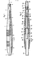
- the first embodiment of the invention shown in FIG. 1 shows an all-plastic outer body 1, 2, 7 which is precisely adapted to the shape of the hand and posture from an ergonomic point of view.
- an adapter 7 With the outer sleeve 1, an adapter 7 is firmly connected.
- the adapter 7 is transparent and allows the filling process and the emptying process to be observed. It carries a rubber grommet 8 in which the microcapillary 9 is guided.
- the microcapillary 9 is still held by the socket 6.
- the secure holding of the capillary 9 is ensured with the two contact surfaces in the socket 6 and in the rubber grommet 8.
- the microcapillary 9 is transparent and provided with markings in order to observe the filling process and the liquid to be absorbed to be able to measure exactly.
- the bellows 5 is connected airtight to the edge of the bush 6.
- the bellows 5 is also welded to the outer sleeve 1.
- the pressure pin 3 protrudes from the outer sleeve 1 of the pipette. It has a cavity 10 which is connected to the outside air via the bore 11.
- the pressure pin 3 is connected to the bellows 5 firmly and airtight.
- the inner volume of the bellows 5 is connected to the cavity 10 of the pressure pin 3 via the opening 12.
- the pressure pin 3 has a shoulder 13 which carries two stop surfaces. In the position shown in FIG. 1, one of the stop surfaces of the stop ring 13 acts with the stop surface. the spacer ring 4 together. The other stop surface of the stop ring 13 cooperates with the stop 14 of the outer sleeve 1 formed by a shoulder in the outer sleeve 1 after the pressure stroke has been carried out. The pressure stroke is limited by these two stops.
- the bellows 5 is preloaded in the state shown in FIG. 1 and therefore presses the stop ring 13 against the spacer ring 4.
- the restoring force of the bellows 5 can be increased by means of a compression spring, not shown, located in the bellows 5.
- the pipette consists exclusively of individual parts that are plugged into one another. With this plug-in technique, the pipette can be easily assembled and, for cleaning purposes, just as easily and completely disassembled without tools.
- the length of the pressure stroke can be adjusted using spacer rings 4 of different lengths.
- the microcapillary 9 When working with the pipette shown in Fig. 1, the microcapillary 9 is first inserted through the very small opening cross section of the rubber grommet 8 into the socket 6 until it stops. In this position, the capillary is ventilated through the bore 15 of the bushing 6, the opening 12 of the bellows 5 and the bore 11 of the pressure pin 3, so that no internal pressure which hinders the capillary action can build up in the pipette. Depending on the geometry of the capillary 9, the entire pipette 1, 2, 7, 9 is brought to the liquid to be sucked up in a certain inclined position. When the capillary tip is immersed in the liquid, the filling process begins by capillary action.
- liquid residues on the outer circumference of the capillary or the tip of the capillary can be dabbed off. If necessary, the liquid level in the capillary 9 can be adjusted by carefully dabbing on a printed mark on the capillary 9.
- the bore 11 at the end of the pressure pin 3 is closed with the finger and then the pressure pin 3 is pressed through evenly until the second stop surface of the stop ring 13 of the pressure pin 3 on the stop 14 inside the outer sleeve 1 is present. In this completely depressed state, the capillary 9 is pulled out of the pipette.
- the pipette After releasing the pressure pin 3, the pipette automatically returns to its starting position due to the restoring force of the bellows 5 which may be increased by a compression spring.
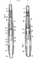
- the outer body of the pipette consists of an outer sleeve 101, an end cap 102 attached to the rear end thereof and an adapter 111 attached to the front end of the outer sleeve 101.
- a microcapillary 120 is frictionally engaged in a rubber grommet 110 which is connected to the outer sleeve 101 kept sealed.
- the microcapillary 120 protrudes through an opening 121 of the adapter 111.
- the rubber grommet 110 is inserted into the outer sleeve 1 and has an area of larger diameter at its end, which is delimited by two stop surfaces.
- stop surfaces lies against the end face of the outer sleeve 1
- the second stop surface lies against a stop surface of the adapter 111 formed by a shoulder.
- the rubber grommet 110 is held firmly by these two stop surfaces when the adapter 111 is connected to the outer sleeve 101.
- outer sleeve 101 In the outer sleeve 101 there is a cylinder part 105, which rests with a shoulder 126 in the interior of the outer sleeve 101.
- the outer sleeve 101 also has a stop 123 on its inner surface.
- a piston 104 is guided in a longitudinally displaceable manner in the interior of the cylinder part 105.
- a sealing ring 109 for sealing the piston against the cylinder part 105.
- the piston 104 has a collar 127 with a larger diameter, on which a compression spring 108 is supported.
- the other The end of the compression spring 108 is supported on a stop 128 on the inner surface of the cylinder part 105.
- the compression spring 108 causes the pipette to perform the suction stroke independently.
- the piston 104 has at its end a smaller-diameter part, on which a pressure pin 103 is pushed up to a stop.
- the pressure pin 3 passes through a bore in the end cap 102 and has on its outer surface a stop ring 122 with two stop surfaces 124, 125.
- the stop surface 125 of the pressure pin 103 bears against the stop surface 126 formed by the end face of the end cap 102.
- the stop 125, 126 is reached independently by the pipette through the action of the compression spring 108.
- the stop formed by the stop surfaces 125, 126 thus limits the suction stroke of the pipette.
- the compression spring 108 is also biased in the position shown in FIG. 2.
- the end face of the pressure pin 103 forms the stop face 128 against which the compression spring 107 rests.
- the other end of the compression spring 107 rests on the stop ring 106 which is guided in a longitudinally displaceable manner on the piston and which in turn rests on the larger-diameter collar 127 of the piston 104.
- the compression spring 107 is biased in the embodiment of the invention shown in FIG. 2.
- vent hole 105a In the cylinder part 105 there is the vent hole 105a, which creates a connection to the outside air.
- the vent hole 105a is located in the area of the working volume 132 of the cylinder directly next to the sealing ring 109 of the piston 104, which delimits the working volume 132.
- a smaller-diameter part 130 of the piston 104 extends into the working volume 132 and terminates with the stop surface 131.
- the diameter of the part 130 of the piston 104 is chosen so that that it can penetrate the bore 133 passing through the cylinder part 105.
- the microcapillary 120 rests on the outer end face of the cylinder part 105.
- the rubber grommet 110 lies in a ring-shaped manner on the outer end face of the cylinder part 105.
- the capillary 120 When using the pipette, the capillary 120 is pushed manually through the opening of the adapter 111 and further through the rubber grommet 110 up to the stop on the front end of the cylinder part 105. In this two-point support, the capillary 120 is tight and tight.
- the piston 104 In the unactuated state shown in FIG. 2, the piston 104 is struck all the way back with the stop surface 125 of the stop ring 122 against the stop surface 126 formed by the end face of the end cap 102 by the force of the compression spring 108. The piston 104 clears the vent hole 105a so that the capillary 120 can now be guided to the liquid with the pipette.
- the capillary 120 is filled by the capillary action. The pressure equalization takes place via the vent hole 105a. If the adapter 111 is transparent, it can be easily observed at which fill level the suction process has to be ended. This can be supported in that the - transparent - capillary carries 120 markings.
- the sucked-in liquid can be transferred to another vessel in that the piston 104 is pressed down against the force of the compression spring 108 via the pressure pin 103.
- the sealing ring 109 moves at the front end of the piston 104 over the vent hole 105a and builds up a slight overpressure on its further path in the working space 132 between the piston 104 or sealing ring 109 and the liquid, which leads to the discharge of the liquid.
- the volume of the work space and the volume of the sucked up Liquid must be in a certain relationship to each other so that the liquid column located in the capillary 120 is completely "blown out" when the capillary 120 is emptied, without air jumping back into the capillary 120.
- the piston 104 At the end of the first stroke, the piston 104 abuts with its stop ring 106 against the stop 134 formed by the end face of the cylinder part 105, as shown in FIG. 3.
- the front end 131 of the smaller-diameter part 130 of the piston 104 is now almost at the rear end of the capillary 120.
- the smaller-diameter part 130 of the piston 104 partially penetrates the bore 133 at the end of the cylinder part 105.
- the relatively high pretensioning force of the compression spring 107 must be overcome like a pressure point. This begins the ejection phase of the capillary 120.
- the movable stop ring 106 runs up to the block length of the compression spring 108 against the front of the pressure pin 103.
- the stroke is ended when the stop surface 124 of the stop ring 122 of the pressure pin 103 strikes the stop surface 123 in the interior of the outer sleeve 101, as shown in FIG. 4.
- the piston 104 sits with the end face 131 of the smaller-diameter part 130 in the exemplary embodiment shown, about 2 mm in front of the constriction of the rubber nozzle 110, and the capillary 120 falls out of its own accord when the pipette is held vertically.
- FIGS. 2 to 4 shows a pipette which holds the capillary tightly and axially, so that it fills itself when a liquid surface is touched.
Abstract
Die Erfindung bezieht sich auf eine Pipette mit elastischem Balg. Zu dem Zweck, eine derartige Pipette zur Aufnahme von Flüssigkeit in selbstaufsaugende Mikrokapillaren derart geeignet zu gestalten, daß sie glechzeitig einfach und zuverlässig zu handhaben ist, ist in dem Balg eine Druckausgleichsöffnung vorgesehen und besitzt die Pipette eine Aufnahme, in der eine Mikrokapillare reibschlüssig gehalten ist.The invention relates to a pipette with an elastic bellows. For the purpose of designing such a pipette for holding liquid in self-absorbing microcapillaries in such a way that it is easy and reliable to handle at the same time, a pressure equalization opening is provided in the bellows and the pipette has a holder in which a microcapillary is held in a frictionally engaged manner .
Description
Die Erfindung betrifft eine Pipette nach dem Oberbegriff des Patentanspruchs 1.The invention relates to a pipette according to the preamble of patent claim 1.
Eine derartige Pipette ist aus der DE-PS 28 51 532 bekannt. Die vorbekannte Pipette besitzt einen elastischen Balg. Der Hub des Balges ist von vorgegebenen Anschlägen begrenzt.Such a pipette is known from DE-PS 28 51 532. The known pipette has an elastic bellows. The bellows stroke is limited by predetermined stops.
Bei der vorbekannten Pipette wird die aufzusaugende Flüssigkeit zunächst durch einen Saughub in die an dem Gehäuse der Pipette befestigte Ansaugspitze eingesaugt. Anschließend wird die Flüssigkeit durch einen Druckhub wieder aus der Pipette ausgestoßen. Die vorbekannte Pipette eignet sich daher nicht für die Aufnahme von Flüssigkeit in selbst aufsaugende Mikrokapillaren, bei denen aufgrund der Kapillarwirkung von Flüssigkeiten die aufzusaugende - Flüssigkeit von einer Mikrokapillare aufgenommen wird, ohne daß, etwa durch einen Saughub, ein gegenüber dem Außendruck verminderter Innendruck erzeugt werden muß. Würde man nämlich einerseits während der Aufnahme der Flüssigkeit in eine selbst aufsaugende Mikrokapillare bei der vorbekannten Pipette die Stellung des Balges und damit das Volumen im Inneren der Pipette unverändert lassen, so käme der Aufsaugvorgang nach kurzer Zeit zum Erliegen, da sich durch die in die Mikrokapillare eindringende Flüssigkeit das Volumen im Inneren der Pipette verringern würde und sich demzufolge ein Druck aufbauen würde, der ein weiteres Eindringen der Flüssigkeit in die Mikrokapillare verhindert. Würde man andererseits vor dem Beginn des Aufsaugvorgangs durch die Mikrokapillare einen Druckhub ausführen, um während des Aufsaugvorgangs einen Saughub ausführen zu können, wäre die Handhabung der vorbekannten Pipette zu kompliziert. Außerdem müßte dann nach Beendigung des Aufsaugvorgangs der Balg exakt in seiner Stellung festgehalten werden, um ein Abreißen des Flüssigkeitsfadens in der Mikrokapillare zu verhindern.In the known pipette, the liquid to be sucked up is first sucked through a suction stroke into the suction tip attached to the housing of the pipette. The liquid is then expelled from the pipette by means of a pressure stroke. The known pipette is therefore not suitable for taking up liquid in self-absorbing microcapillaries in which, due to the capillary action of liquids, the liquid to be sucked up is taken up by a microcapillary, without an internal pressure being reduced compared to the external pressure, for example by a suction stroke got to. One would namely during the absorption of the liquid into a self-absorbing microcapillary in the known pipette, the position of the bellows and thus the volume inside the pipette remain unchanged, the suction process would come to a standstill after a short time, since the volume penetrating through the microcapillary would decrease inside the pipette and consequently a pressure would build up, which prevents further penetration of the liquid into the microcapillary. If, on the other hand, one were to carry out a pressure stroke through the microcapillary before the start of the suction process in order to be able to carry out a suction stroke during the suction process, the handling of the known pipette would be too complicated. In addition, the bellows would then have to be held exactly in its position after the completion of the suction process in order to prevent the liquid thread in the microcapillary from being torn off.
Aufgabe der Erfindung ist es also, eine Pipette der eingangs angegebenen Art zu schaffen, die zur Aufnahme von Flüssigkeit in selbst aufsaugende Mikrokapillaren geeignet ist und die einfach und zuverlässig zu handhaben ist.The object of the invention is therefore to provide a pipette of the type specified at the outset which is suitable for holding liquid in self-absorbing microcapillaries and which is simple and reliable to use.
Erfindungsgemäß wird diese Aufgabe dadurch gelöst, daß in dem Balg eine Druckausgleichsöffnung vorgesehen ist. Während des Aufsaugvorgangs kann also ein Druckausgleich stattfinden. Dadurch kann sich im Inneren der Kapillare kein Überdruck aufbauen, der die weitere Flüssigkeitsaufnahme in der Mikrokapillare behindern würde. Während der Flüssigkeitsaufnahme kann die Bedienungsperson sich allein darauf beschränken, den Aufnahmevorgang zu beobachten; weitere Maßnahmen ihrerseits sind nicht erforderlich. Auch nach Abschluß der Flüssigkeitsaufnahme bleibt die einmal aufgenommene Flüssigkeitsmenge ohne Zutun der Bedienungsperson zuverlässig in der Mikrokapillare. Die Flüssigkeit kann dadurch aus der Mikrokapillare entfernt werden, daß die Bedienungsperson die Druckausgleichsöffnung verschließt und einen Druckhub ausführt. Durch den Uberdruck in der Kapillare wird dann die Flüssigkeit herausgedrückt.According to the invention, this object is achieved in that a pressure compensation opening is provided in the bellows. A pressure equalization can therefore take place during the suction process. As a result, no excess pressure can build up in the interior of the capillary, which would hinder further liquid absorption in the microcapillary. During the liquid intake, the operator can limit himself to observing the intake process; further measures on your part are not required. Even after completion of the liquid intake, the amount of liquid once taken up remains reliably in the microcapillary without the operator having to do anything. The liquid can be removed from the microcapillary by the operator closing the pressure compensation opening and executes a pressure stroke. The liquid is then pressed out by the excess pressure in the capillary.
In weiterer Ausgestaltung der Erfindung besitzt die Pipette eine Aufnahme, in der eine Mikrokapillare reibschlüssig gehalten ist. Dadurch ist ein schnelles und einfaches Auswechseln der Mikrokapillare möglich. Die Aufnahme kann aus einer Gummitülle bestehen, die der Mikrokapillare auf besonders einfache Weise einen sicheren und dichten Halt gibt. Wenn die Aufnahme aus zwei im Abstand voneinander angeordneten Auflageflächen besteht, ist eine besonders sichere Haltung der Kapillare gewährleistet.In a further embodiment of the invention, the pipette has a holder in which a microcapillary is held in a frictionally engaged manner. This enables the microcapillary to be replaced quickly and easily. The receptacle can consist of a rubber grommet, which gives the microcapillary a secure and tight hold in a particularly simple manner. If the receptacle consists of two support surfaces arranged at a distance from one another, a particularly secure holding of the capillary is ensured.
Dadurch, daß ein Teil der Außenhülse der Pipette von einem Adapter für die Mikrokapillare gebildet wird, ist es möglich, die erfindungsgemäße Pipette durch Auswechseln des Adapters auf schnelle und einfache Weise an Mikrokapillaren verschiedener Abmessungen, insbesondere verschiedenen Durchmessers, anzupassen.Because part of the outer sleeve of the pipette is formed by an adapter for the microcapillary, it is possible to adapt the pipette according to the invention to microcapillaries of different dimensions, in particular different diameters, in a quick and simple manner by changing the adapter.
Wenn die Kapillare durchsichtig ist, kann der Füllstand der Flüssigkeit in der Kapillare beobachtet werden. Durch eine Bemaßung der-Kapillare können vorbestimmte Mengen der aufzusaugenden Flüssigkeit einfach und genau abgemessen werden. Dadurch, daß die Außenhülse bzw. der Adapter im Bereich der Kapillare durchsichtig ist, kann die aufzusaugende Flüssigkeit über eine größere oder gegebenenfalls über die gesamte Länge der Kapillare beobachtet und/oder abgemessen werden.If the capillary is transparent, the level of the liquid in the capillary can be observed. By dimensioning the capillary, predetermined amounts of the liquid to be sucked up can be measured simply and precisely. Because the outer sleeve or the adapter is transparent in the area of the capillary, the liquid to be sucked up can be observed and / or measured over a greater or possibly over the entire length of the capillary.
Wenn der Balg mit einem aus der Außenhülse der Pipette herausragenden Druckstift verbunden ist, kann er auf einfache Weise von der Bedienungsperson betätigt werden. Wenn sich die Druckausgleichsöffnung an der Druckfläche des Druckstiftes, der hohl und mit dem Balg luftdicht verbunden ist, befindet, kann diese Druckausgleichsöffnung auf einfache Weise durch Auflegen eines Fingers, insbesondere des den Druckstift betätigenden Fingers der Bedienungsperson, verschlossen werden.If the bellows is connected to a push pin protruding from the outer sleeve of the pipette, it can be actuated in a simple manner by the operator. If the pressure equalization opening is on the pressure surface of the pressure pin, which is hollow and airtightly connected to the bellows, this pressure equalization opening can be easily made by placing a Fingers, in particular the operator's finger actuating the pressure pin, are closed.
Dadurch, daß der Balg in vorteilhafter Ausgestaltung der Erfindung eine Federwirkung in Richtung auf seine Stellung mit größerem Volumen aufweist, wird die Pipette nach dem Ausstoßen der Flüssigkeit von selbst in ihre Ausgangsstellung zurückbewegt. Diese Wirkung kann dadurch verstärkt werden, daß der Balg mit einer Druckfeder versehen ist.Because the bellows in an advantageous embodiment of the invention has a spring action in the direction of its position with a larger volume, the pipette is automatically moved back into its initial position after the liquid has been ejected. This effect can be enhanced by providing the bellows with a compression spring.
Wenn mit einer Pipette bakterizide Stoffe oder toxische Reagenzien behandelt werden sollen, muß gewährleistet sein, daß die Bedienungsperson nicht mit derartigen Substanzen in Berührung kommt. Vielfach werden jedoch für solche Arbeiten Flüssigkeitsaufnehmer, insbesondere Mikrokapillaren, verwendet, die manuell in die Pipette eingesetzt werden müssen.If bactericidal substances or toxic reagents are to be treated with a pipette, it must be ensured that the operator does not come into contact with such substances. In many cases, however, liquid sensors, in particular microcapillaries, are used for such work, which have to be inserted manually into the pipette.
Es ist daher eine weitere Aufgabe der Erfindung, eine Pipette zu schaffen, die einfach und zuverlässig zu handhaben ist und bei der der Flüssigkeitsaufnehmer, insbesondere eine Mikrokapillare, ohne Zuhilfenahme der Hand aus der Pipette entfernt werden kann bzw. von der Pipette getrennt werden kann.It is therefore a further object of the invention to provide a pipette which is simple and reliable to handle and in which the liquid receiver, in particular a microcapillary, can be removed from the pipette or separated from the pipette without the aid of the hand.
Diese Aufgabe wird bei einer Pipette mit einem Flüssigkeitsaufnehmer dadurch gelöst, daß der Flüssigkeisaufnehmer in einer Aufnahme reibschlüssig und abdichtend gehalten ist, daß ein Kolben in einem Zylinder längsverschieblich geführt ist und daß der Kolben über das Ende des Druckhubes hinaus bewegt werden kann, um den Flüssigkeitsaufnehmer aus seiner Aufnahme herauszubewegen. Dadurch, daß der Flüssigkeitsaufnehmer in einer Aufnahme reibschlüssig gehalten ist, kann er durch einen Druck in Längsrichtung aus der Aufnahme herausbewegt werden. Dadurch, daß ein Kolben in einem Zylinder längsverschieblich geführt ist und über das Ende des Druckhubes hinaus bewegt werden kann, um den Flüspigkeitsaufnehmer aus seiner Aufnahme herauszubewegen, kann der Flüssigkeitsaufnehmer ohne Berührung von Hand aus der Aufnahme entfernt und von der Pipette getrennt werden. Dadurch, daß der Flüssigkeitsaufnehmer in einer Aufnahme abdichtend gehalten ist, kann sich während des Druckhubes der zum Ausstoß der in dem Flüssigkeitsaufnehmer befindlichen Flüssigkeit erforderliche Überdruck bilden.This object is achieved in a pipette with a liquid pickup in that the liquid ice pickup is frictionally and sealingly held in a receptacle, that a piston in a cylinder is guided in a longitudinally displaceable manner and that the piston can be moved beyond the end of the pressure stroke to the liquid pickup to move out of his admission. Because the liquid receiver is held in a receptacle by friction, it can be moved out of the receptacle by a pressure in the longitudinal direction. Characterized in that a piston is guided longitudinally in a cylinder and can be moved beyond the end of the pressure stroke to the To move the liquid receiver out of its holder, the liquid holder can be removed from the holder without touching it and separated from the pipette. Characterized in that the liquid receiver is held sealingly in a receptacle, the overpressure required to eject the liquid in the liquid receiver can form during the pressure stroke.
In vorteilhafter Weiterbildung der Erfindung besteht die Aufnahme aus einer Gummitülle, die eine besonders einfache und sichere reibschlüssige Halterung des Flüssigkeitsaufnehmers gewährleistet und den Flüssigkeitsaufnehmer zum Kolben abdichtet. Wenn die Aufnahme aus zwei im Abstand voneinander angeordneten Auflageflächen besteht, wird der Flüssigkeitsaufnehmer durch diese Zweipunktauflage besonders dicht und fest gehalten. Durch einen Adapter für die Aufnahme des Flüssigkeitsaufnehmers wird eine Anpassungsmöglichkeit an Flüssigkeitsaufnehmer verschiedener Außenabmessungen geschaffen.In an advantageous development of the invention, the receptacle consists of a rubber grommet, which ensures a particularly simple and secure frictional holding of the liquid receiver and seals the liquid receiver to the piston. If the receptacle consists of two support surfaces arranged at a distance from one another, the liquid receiver is held particularly tightly and firmly by this two-point support. An adapter for accommodating the liquid receiver creates a possibility of adaptation to liquid receivers of different external dimensions.
Die Verbindung des Kolbens mit einem aus der Außenhülse der Pipette herausragenden Druckstift ermöglicht eine einfache Betätigung der Pipette.The connection of the piston with a pressure pin protruding from the outer sleeve of the pipette enables the pipette to be actuated easily.
Durch eine Begrenzung des Kolbenhubes durch Anschläge ist eine einfache und genau reproduzierbare Möglichkeit der Flüssigkeitsabmessung gegeben. Wenn der Kolben durch eine Druckfeder an der Außenhülse abgestützt ist, wird der Saughub des Kolbens durch Federkraft bewirkt, was die Handhabung erleichtert.Limiting the piston stroke by means of stops provides a simple and precisely reproducible possibility of measuring the liquid. If the piston is supported on the outer sleeve by a compression spring, the suction stroke of the piston is effected by spring force, which makes handling easier.
Bei einer besonders vorteilhaften Weiterbildung der Erfindung ist eine Druckfeder vorgesehen, die sich einerseits an dem Kolben und andererseits an einem Anschlagring abstützt, welcher während des Druckhubes an einem Anschlag des Kolbens und anschließend an einem Anschlag der Außenhülse anliegt. Dadurch muß nach dem Ende des Druckhubes beim weiteren Niederdrücken des Kolbens druckpunktartig die Kraft der Druckfeder überwunden werden, wodurch der Bedienungsperson auf zuverlässige Weise fühlbar das Ende des Druckhubes und der Beginn der Ausstoßphase des Flüssigkeitsaufnehmers angezeigt wird. Dieser Vorteil kann dadurch verstärkt werden, daß die Druckfeder vorgespannt und/oder härter ist als die die selbstätige Ausführung des Saughubes auslösende Druckfeder.In a particularly advantageous development of the invention, a compression spring is provided which is supported on the one hand on the piston and on the other hand on a stop ring which bears against a stop of the piston during the pressure stroke and subsequently against a stop of the outer sleeve. Thereby After the end of the pressure stroke, the force of the compression spring must be overcome like a pressure point when the piston is further depressed, as a result of which the operator can feel the end of the pressure stroke and the start of the ejection phase of the liquid sensor in a reliable manner. This advantage can be increased in that the compression spring is pre-tensioned and / or harder than the compression spring which triggers the automatic execution of the suction stroke.
In vorteilhafter Weiterbildung der Erfindung ist ein Zylinderteil vorgesehen, das an einem Absatz der Außenhülse anliegt und Anschläge für die Druckfeder und für den Anschlagring aufweist. Dieser Zylinderteil kann auf einfache Weise in die Außenhülse der Pipette eingesteckt werden, was die Montage erleichtert.In an advantageous development of the invention, a cylinder part is provided which bears on a shoulder of the outer sleeve and has stops for the compression spring and for the stop ring. This cylinder part can be easily inserted into the outer sleeve of the pipette, which makes assembly easier.
Wenn der mit dem Kolben verbundene Druckstift einen Anschlag für die Druckfeder und Anschlagflächen für die Begrenzung des Kolbenhubes aufweist, können dieser Anschlag und diese Anschlagflächen auf einfache Weise dadurch gebildet werden, daß der Druckstift auf den Kolben aufgesteckt wird, was ebenfalls die Montage erleichtert. Eine von der Außenhülse getragene Endkappe mit einem Anschlag zur Begrenzung des Kolbenhubes führt auch zu einer Montageerleichterung.If the pressure pin connected to the piston has a stop for the compression spring and stop surfaces for limiting the piston stroke, this stop and these stop surfaces can be formed in a simple manner by pushing the pressure pin onto the piston, which also facilitates assembly. An end cap carried by the outer sleeve with a stop for limiting the piston stroke also makes assembly easier.
In vorteilhafter Weiterbildung der Erfindung besteht der Flüssigkeitsaufnehmer aus einer Mikrokapillare und ist eine Druckausgleichsöffnung in dem Zylinder vorgesehen. Die Pipette ist damit geeignet, mit selbst aufsaugenden Mikrokapillaren verwendet zu werden. Die Vorteile, die sich daraus ergeben, daß die Mikrokapillare durchsichtig ist, daß die Mikrokapillare bemaßt ist und daß die Außenhülse im Bereich der Mikrokapillare durchsichtig ist, wurden bereits dargelegt.In an advantageous development of the invention, the liquid receiver consists of a microcapillary and a pressure compensation opening is provided in the cylinder. The pipette is therefore suitable for use with self-aspirating microcapillaries. The advantages which result from the fact that the microcapillary is transparent, that the microcapillary is dimensioned and that the outer sleeve in the area of the microcapillary is transparent have already been explained.
Wenn sich die Druckausgleichsöffnung im Arbeitsraum an einer Stelle befindet, an der sie unmittelbar nach Beginn des Druckhubes geschlossen wird, kann bei Verwendung einer Mikrokapillare der Druckhub über seine größtmögliche Länge ausgenutzt werden. Dies ist auch dann möglich, wenn der oben beschriebene Zylinderteil verwendet wird.If the pressure equalization opening in the work area is at a Where it is closed immediately after the start of the pressure stroke, the pressure stroke can be used over its greatest possible length when using a microcapillary. This is also possible if the cylinder part described above is used.
Ausführungsbeispiele der Erfindung werden nachfolgend anhand der beigefügten Zeichnungen beschrieben. In diesen zeigen
- Fig. 1 eine erste Ausführungsform der Erfindung,
- Fig. 2 eine zweite Ausführungsform der Erfindung vor Beginn des Druckhubes,
- Fig. 3 die Ausführungsform nach Fig. 2 am Ende des Druckhubes und
- Fig. 4 die Ausführungsform der Erfindung nach den Fig. 2 und 3 nach Ausführung der den Flüssigkeitsaufnehmer aus der Aufnahme herausbewegenden Bewegung.
- 1 shows a first embodiment of the invention,
- 2 shows a second embodiment of the invention before the start of the pressure stroke,
- Fig. 3 shows the embodiment of FIG. 2 at the end of the pressure stroke and
- Fig. 4 shows the embodiment of the invention according to FIGS. 2 and 3 after execution of the movement moving the liquid receiver out of the receptacle.
Die in der Fig. 1 dargestellte erste Ausführungsform der Erfindung zeigt einen Vollkunststoffaußenkörper 1, 2, 7, der der Handform und Handhaltung nach ergonomischen Gesichtspunkten exakt angepaßt ist. Mit der Außenhülse 1 ist ein Adapter 7 fest verbunden. Der Adapter 7 ist transparent und gestattet die Beobachtung des Füllvorgangs und des Entleerungsvorgangs. Er trägt eine Gummitülle 8, in der die Mikrokapillare 9 geführt ist. Die Mikrokapillare 9 wird weiterhin von der Buchse 6 gehalten. Die sichere Haltung der Kapillare 9 wird mit den zwei Auflageflächen in der Buchse 6 und in der Gummitülle 8 gewährleistet. Die Mikrokapillare 9 ist durchsichtig und mit Markierungen versehen, um den Füllvorgang beobachten und die aufzunehmende Flüssigkeit exakt abmessen zu können. Der Faltenbalg 5 ist luftdicht mit dem Rand der Buchse 6 verbunden. Der Faltenbalg 5 ist weiterhin mit der Außenhülse 1 verschweißt. Aus der Außenhülse 1 der Pipette ragt der Druckstift 3 heraus. Er weist einen Hohlraum 10 auf, der über die Bohrung 11 mit der Außenluft verbunden ist. Der Druckstift 3 ist mit dem Faltenbalg 5 fest und luftdicht verbunden. Das Innenvolumen des Faltenbalges 5 ist über die Öffnung 12 mit dem Hohlraum 10 des Druckstiftes 3 verbunden. Mit der Außenhülse 1 ist eine Endkappe 2 verbunden, in der der Druckstift 3 geführt ist. An die Endkappe 2 schließt sich im Innern der Außenhülse 1 ein Distanzring 4 an.The first embodiment of the invention shown in FIG. 1 shows an all-plastic outer body 1, 2, 7 which is precisely adapted to the shape of the hand and posture from an ergonomic point of view. With the outer sleeve 1, an adapter 7 is firmly connected. The adapter 7 is transparent and allows the filling process and the emptying process to be observed. It carries a rubber grommet 8 in which the microcapillary 9 is guided. The microcapillary 9 is still held by the
Der Druckstift 3 weist einen Absatz 13 auf, der zwei Anschlagflächen trägt. In der in Fig. 1 gezeigten Stellung wirkt eine der Anschlagflächen des Anschlagrings 13 mit der Anschlagfläche . des Distanzrings 4 zusammen. Die andere Anschlagfläche des Anschlagrings 13 wirkt nach Ausführung des Druckhubes mit der durch einen Absatz in der Außenhülse 1 gebildeten Anschlag 14 der Außenhülse 1 zusammen. Durch diese beiden Anschläge ist der Druckhub begrenzt.The pressure pin 3 has a
Der Faltenbalg 5 ist in dem in Fig. 1 gezeigten Zustand vorgespannt und drückt daher den Anschlagring 13 gegen den Distanzring 4. Die Rückstellkraft des Faltenbalges 5 kann mittels einer in dem Faltenbalg 5 befindlichen, nicht gezeigten Druckfeder verstärkt sein.The
Die Pipette besteht ausschließlich aus ineinandergesteckten Einzelteilen. Durch diese Stecktechnik kann die Pipette in einfacher Weise montiert und, etwa zu Reinigungszwecken, ebenso einfach ohne Werkzeug vollständig demontiert werden.The pipette consists exclusively of individual parts that are plugged into one another. With this plug-in technique, the pipette can be easily assembled and, for cleaning purposes, just as easily and completely disassembled without tools.
Durch Distanzringe 4 verschiedener Länge kann die Länge des Druckhubes eingestellt werden.The length of the pressure stroke can be adjusted using spacer rings 4 of different lengths.
Beim Arbeiten mit der in Fig. 1 dargestellten Pipette wird zunächst die Mikrokapillare 9 durch den sehr kleinen Öffnungsquerschnitt der Gummitülle 8 in die Buchse 6 bis zum Anschlag eingeschoben. In dieser Stellung ist die Kapillare durch die Bohrung 15 der Buchse 6, die Öffnung 12 des Faltenbalges 5 und die Bohrung 11 des Druckstifts 3 belüftet, so daß sich kein die Kapillarwirkung behindernder Innendruck in der Pipette aufbauen kann. Abhängig von der Geometrie der Kapillare 9 wird die gesamte Pipette 1, 2, 7, 9 in bestimmter Schräglage an die aufzusaugende Flüssigkeit herangeführt. Mit dem Eintauchen der Kapillarenspitze in die Flüssigkeit beginnt der Füllvorgang durch Kapillarwirkung. Nach dem Herausnehmen der gefüllten Kapillare aus der Flüssigkeit können Flüssigkeitsreste am äußeren Umfang der Kapillare bzw. der Spitze der Kapillare abgetupft werden. Gegebenenfalls kann der Flüssigkeitsstand in der Kapillare 9 durch vorsichtiges Abtupfen auf eine aufgedruckte Marke an der Kapillare 9 eingestellt werden. Zur Übergabe der Flüssigkeit an ein Teil zur weiteren Untersuchung wird mit dem Finger die Bohrung 11 am Ende des Druckstifts 3 verschlossen und anschließend der Druckstift 3 gleichmäßig durchgedrückt, bis die zweite Anschlagfläche des Anschlagrings 13 des Druckstifts 3 an dem Anschlag 14 im Inneren der Außenhülse 1 anliegt. In diesem vollständig niedergedrückten Zustand wird die Kapillare 9 aus der Pipette herausgezogen.When working with the pipette shown in Fig. 1, the microcapillary 9 is first inserted through the very small opening cross section of the rubber grommet 8 into the
Nach dem Loslassen des Druckstifts 3 kehrt die Pipette selbständig aufgrund der möglicherweise durch eine Druckfeder verstärkten Rückstellkraft des Faltenbalges 5 in ihre Ausgangsstellung zurück.After releasing the pressure pin 3, the pipette automatically returns to its starting position due to the restoring force of the
Durch die Anlage des Fingers der Bedienungsperson an dem Ende des Druckstifts 3 wird mit derselben Bewegung sowohl die Bohrung 11 des Druckstifts 3 verschlossen als auch der Druckstift 3 und damit der Faltenbalg 5 in Richtung des Druckhubes bewegt. Durch das Verschließen der Bohrung 11 kann während des Druckhubes keine Luft aus dem Inneren der Pipette entweichen, wodurch der zum Herausdrücken der in der Kapillare befindlichen Flüssigkeit erforderliche Überdruck durch eine einzige Bewegung erzeugt wird.By placing the operator's finger on the end of the pressure pin 3, both the bore 11 of the pressure pin 3 and the pressure pin 3 and so that the
In den Fig. 2 bis 4 ist eine zweite Ausführungsform der Erfindung gezeigt. Der Außenkörper der Pipette besteht aus einer Außenhülse 101, einer an deren hinterem Ende befestigten Endkappe 102 und aus einem am vorderen Ende der Außenhülse 101 befestigten Adapter 111. Eine Mikrokapillare 120 ist in einer Gummitülle 110, die mit der Außenhülse 101 verbunden ist, reibschlüssig und abdichtend gehalten. Die Mikrokapillare 120 ragt durch eine Öffnung 121 des Adapters 111. Die Gummitülle 110 wird in die Außenhülse 1 eingeschoben und weist an ihrem Ende einen Bereich größeren Durchmessers auf, der von zwei Anschlagflächen begrenzt ist. Eine dieser Anschlagflächen liegt an der Stirnfläche der Außenhülse 1 an, die zweite Anschlagfläche liegt an einer durch einen Absatz gebildeten Anschlagfläche des Adapters 111 an. Durch diese beiden Anschlagflächen wird die Gummitülle 110 bei mit der Außenhülse 101 verbundenem Adapter 111 fest gehalten.2 to 4, a second embodiment of the invention is shown. The outer body of the pipette consists of an
In der Außenhülse 101 befindet sich ein Zylinderteil 105, welches mit einem Absatz 126 im Inneren der Außenhülse 101 an diese anliegt. Die Außenhülse 101 weist weiterhin an ihrer Innenfläche einen Anschlag 123 auf.In the
Im Inneren des Zylinderteils 105 ist ein Kolben 104 längsverschieblich geführt. In einer Nut des Kolbens 104 befindet sich ein Dichtring 109 zur Abdichtung des Kolbens gegenüber dem Zylinderteil 105. Der Kolben 104 weist einen durchmessergrößeren Bund 127 auf, an dem eine Druckfeder 108 abgestützt ist. Das andere Ende der Druckfeder 108 stützt sich an einem Anschlag 128 an der Innenfläche des Zylinderteils 105 ab. Die Druckfeder 108 bewirkt die selbständige Ausführung des Saughubes der Pipette.A
Der Kolben 104 weist an seinem Ende einen durchmesserkleineren Teil auf, auf den ein Druckstift 103 bis zu einem Anschlag aufgesteckt ist. Der Druckstift 3 durchsetzt eine Bohrung der Endkappe 102 und weist an seiner Außenfläche einen Anschlagring 122 mit zwei Anschlagflächen 124, 125 auf. In der in Fig. 2 gezeigten Stellung liegt die Anschlagfläche 125 des Druckstifts 103 an der durch die Stirnseite der Endkappe 102 gebildeten Anschlagfläche 126 an. Der Anschlag 125, 126 wird von der Pipette selbständig erreicht durch die Wirkung der Druckfeder 108. Der durch die Anschlagflächen 125, 126 gebildete Anschlag begrenzt also den Saughub der Pipette. Bei dem in Fig. 2 gezeigten Ausführungsbeispiel der Erfindung ist die Druckfeder 108 auch in der in Fig. 2 gezeigten Stellung noch vorgespannt.The
Die Stirnfläche des Druckstifts 103 bildet die Anschlagfläche 128, an der die Druckfeder 107 anliegt. Das andere Ende der Druckfeder 107 liegt an dem auf dem Kolben längsverschieblich geführten Anschlagring 106 an, der seinerseits an dem durchmessergrößeren Bund 127 des Kolbens 104 anliegt. Die Druckfeder 107 ist bei dem in Fig. 2 gezeigten Ausführungsbeispiel der Erfindung vorgespannt.The end face of the
In dem Zylinderteil 105 befindet sich die Entlüftungsbohrung 105a, die ein Verbindung zur Außenluft herstellt. Die Entlüftungsbohrung 105a befindet sich im Bereich des Arbeitsvolumens 132 des Zylinders unmittelbar neben dem Dichtring 109 des Kolbens 104, der das Arbeisvolumen 132 begrenzt. In das Arbeitsvolumen 132 erstreckt sich ein durchmesserkleinerer Teil 130 des Kolbens 104, der mit der Anschlagfläche 131 abschließt. Der Durchmesser des Teils 130 des Kolbens 104 ist dabei so gewählt, daß er die den Zylinderteil 105 durchsetzende Bohrung 133 durchdringen kann. An der äußeren Stirnfläche des Zylinderteils 105 liegt die Mikrokapillare 120 an. Weiterhin liegt an der äußeren Stirnfläche des Zylinderteils 105 die Gummitülle 110 ringförmig abschließend an.In the
Beim Gebrauch der Pipette wird die Kapillare 120 manuell durch die Öffnung des Adapters 111 und weiterführend durch die Gummitülle 110 bis zum Anschlag an die vordere Stirnseite des Zylinderteils 105 geschoben. In dieser Zweipunktauflage sitzt die Kapillare 120 dicht und fest. In dem in Fig. 2 gezeigten unbetätigten Zustand ist der Kolben 104 ganz nach hinten mit der Anschlagfläche 125 des Anschlagrings 122 an die von der Stirnfläche der Endkappe 102 gebildete Anschlagfläche 126 durch die Kraft der Druckfeder 108 angeschlagen. Der Kolben 104 gibt dabei die Entlüftungsbohrung 105a frei, so daß nun die Kapillare 120 mit der Pipette an die Flüssigkeit geführt werden kann. Durch die Kapillarwirkung wird die Kapillare 120 gefüllt. Der Druckausgleich erfolgt über die Entlüftungsbohrung 105a. Wenn der Adapter 111 transparent ist, kann gut beobachtet werden, bei welchem Füllstand der Ansaugvorgang beendet werden muß. Dies kann dadurch unterstützt werden, daß die - durchsichtige - Kapillare 120 Markierungen trägt.When using the pipette, the capillary 120 is pushed manually through the opening of the
Nach Beendigung des Ansaugvorgangs kann die angesaugte Flüssigkeit in ein anderes Gefäß übertragen werden, indem der Kolben 104 über den Druckstift 103 gegen die Kraft der Druckfeder 108 niedergedrückt wird. Dabei bewegt sich der Dichtring 109 am vorderen Ende des Kolbens 104 über die Entlüftungsbohrung 105a hinweg und baut auf seinem weiteren Weg in dem Arbeitsraum 132 zwischen Kolben 104 bzw. Dichtring 109 und Flüssigkeit einen leichten Überdruck auf, der zum Ausstoß der Flüssigkeit führt. Das Volumen des Arbeitsraumes und das Volumen der aufgesaugten Flüssigkeit müssen in einem bestimmten Verhältnis zueinander stehen, damit die in der Kapillare 120 befindliche Flüssigkeitssäule beim Entleeren der Kapillare 120 ohne Rücksprung von Luft in die Kapillare 120 vollständig "ausgeblasen" wird.After the suction process has ended, the sucked-in liquid can be transferred to another vessel in that the
Am Ende des ersten Hubweges liegt der Kolben 104 mit seinem Anschlagring 106 an dem von der Stirnfläche des Zylinderteils 105 gebildeten Anschlag 134 an, wie es in Fig. 3 gezeigt ist. Das vordere Ende 131 des durchmesserkleineren Teils 130 des Kolbens 104 steht nun fast am hinteren Ende der Kapillare 120 an. Der durchmesserkleinere Teil 130 des Kolbens 104 durchsetzt dabei teilweise die Bohrung 133 am Ende des Zylinderteils 105.At the end of the first stroke, the
Beim weiteren Niederdrücken des Kolbens 104 muß druckpunktartig die relativ hohe Vorspannkraft der Druckfeder 107 überwunden werden. Damit beginn die Ausstoßphase der Kapillare 120. Der bewegliche Anschlagring 106 läuft bis fast zur Blocklänge der Druckfeder 108 gegen die Vorderseite des Druckstiftes 103.When the
Der Hub ist beendet, wenn die Anschlagfläche 124 des Anschlagrings 122 des Druckstifts 103 an die Anschlagfläche 123 im Inneren der Außenhülse 101 anschlägt, wie es in Fig. 4 gezeigt ist. In diesem Zustand sitzt der Kolben 104 mit der Stirnfläche 131 des durchmesserkleineren Teils 130 bei dem gezeigten Ausführungsbeispiel etwa 2 mm vor der Engstelle der Gummitülle 110, und die Kapillare 120 fällt bei Vertikalhaltung der Pipette von selbst heraus.The stroke is ended when the
Durch das in den Fig. 2 bis 4 dargestellte Ausführungsbeispiel der Erfindung wird eine Pipette gezeigt, die die Kapillare dicht und axial festhält, so daß sie sich beim Berühren einer Flüssigkeitsoberfläche von selbst füllt.The exemplary embodiment of the invention shown in FIGS. 2 to 4 shows a pipette which holds the capillary tightly and axially, so that it fills itself when a liquid surface is touched.
Beim Niederdrücken des Druckstifts wird zunächst die eingesaugte Flüssigkeit gleichmäßig langsam und ohne Abreißen des Flüssigkeitsfadens abgegeben. Anschließend wird die Kapillare durch weiteres Niederdrücken des Druckstifts ohne Zuhilfenahme der Hand aus der Pipette ausgestossen.When the pressure pin is pressed down, the liquid that is sucked in is first released evenly slowly and without tearing off the liquid thread. The capillary is then ejected from the pipette by pressing the pressure pin down further without the aid of the hand.
Claims (14)
Priority Applications (1)
| Application Number | Priority Date | Filing Date | Title |
|---|---|---|---|
| AT86117244T ATE50518T1 (en) | 1985-12-12 | 1986-12-11 | PIPETTE. |
Applications Claiming Priority (4)
| Application Number | Priority Date | Filing Date | Title |
|---|---|---|---|
| DE3543950 | 1985-12-12 | ||
| DE3543950 | 1985-12-12 | ||
| DE3614085 | 1986-04-25 | ||
| DE19863614085 DE3614085A1 (en) | 1985-12-12 | 1986-04-25 | PIPETTE |
Publications (3)
| Publication Number | Publication Date |
|---|---|
| EP0232517A2 true EP0232517A2 (en) | 1987-08-19 |
| EP0232517A3 EP0232517A3 (en) | 1988-06-22 |
| EP0232517B1 EP0232517B1 (en) | 1990-02-28 |
Family
ID=25838773
Family Applications (1)
| Application Number | Title | Priority Date | Filing Date |
|---|---|---|---|
| EP86117244A Expired - Lifetime EP0232517B1 (en) | 1985-12-12 | 1986-12-11 | Pipette |
Country Status (3)
| Country | Link |
|---|---|
| US (1) | US4784834A (en) |
| EP (1) | EP0232517B1 (en) |
| DE (2) | DE3614085A1 (en) |
Cited By (2)
| Publication number | Priority date | Publication date | Assignee | Title |
|---|---|---|---|---|
| EP0351761A2 (en) * | 1988-07-18 | 1990-01-24 | The Perkin-Elmer Corporation | Sample injector |
| EP3248683A1 (en) * | 2016-05-24 | 2017-11-29 | KABE-Labortechnik GmbH | Capillary draining aid |
Families Citing this family (28)
| Publication number | Priority date | Publication date | Assignee | Title |
|---|---|---|---|---|
| US5104625A (en) * | 1989-10-04 | 1992-04-14 | Drummond Scientific Company | Pipetter device |
| DE4341229C2 (en) * | 1993-12-03 | 1995-09-07 | Eppendorf Geraetebau Netheler | Pipette system |
| US5623106A (en) * | 1995-06-06 | 1997-04-22 | Johnson & Johnson Clinical Diagnostics, Inc. | Method and apparatus for forming disposable tips in an analyzer |
| DE19922285A1 (en) * | 1999-05-14 | 2000-11-16 | Febit Ferrarius Biotech Gmbh | Sample vessel used for handling liquids, powders and granules has two front ends with a casing between the ends to limit a sample vessel chamber |
| GB9917325D0 (en) | 1999-07-23 | 1999-09-22 | Clinical Diagnostic Chemicals | Apparatus for collecting a liquid sample |
| DE10011235C2 (en) * | 2000-03-08 | 2002-08-08 | Max Planck Gesellschaft | Stitching device for sample taking and method for taking a sample |
| DE102005033378B4 (en) * | 2005-07-16 | 2012-05-31 | Eppendorf Ag | pipette |
| DE102005041183B3 (en) * | 2005-08-31 | 2007-01-04 | Eppendorf Ag | Two-part pipetting system for metering liquids, has lower spigot which is secured in its holder by snap hooks with catches and released by wedge system actuated by movement of unlocking ring |
| JP5122091B2 (en) | 2006-06-13 | 2013-01-16 | ユニバーサル・バイオ・リサーチ株式会社 | Carrier-enclosed deformed container, carrier-enclosed deformed container processing apparatus, and carrier-enclosed deformed container processing method |
| EP3181228B1 (en) | 2007-10-02 | 2020-07-29 | Labrador Diagnostics LLC | Modular point-of-care devices and uses thereof |
| GB2467929A (en) * | 2009-02-19 | 2010-08-25 | Nordiag Asa | Pipette with bellows |
| CN102740978A (en) * | 2009-12-18 | 2012-10-17 | 扎芬纳股份公司 | Micropipette |
| US8372354B2 (en) * | 2010-07-19 | 2013-02-12 | Chevron U.S.A. Inc. | Multiphase contact and distribution apparatus for hydroprocessing |
| BR112013018656B1 (en) | 2011-01-21 | 2021-03-02 | Labrador Diagnostics Llc | method for detecting the presence or concentration of an analyte in a sample of fluid contained in a container, and, method of measuring the concentration of analyte in a sample of fluid |
| US9632102B2 (en) | 2011-09-25 | 2017-04-25 | Theranos, Inc. | Systems and methods for multi-purpose analysis |
| US8475739B2 (en) | 2011-09-25 | 2013-07-02 | Theranos, Inc. | Systems and methods for fluid handling |
| US9664702B2 (en) | 2011-09-25 | 2017-05-30 | Theranos, Inc. | Fluid handling apparatus and configurations |
| US20140170735A1 (en) | 2011-09-25 | 2014-06-19 | Elizabeth A. Holmes | Systems and methods for multi-analysis |
| US8840838B2 (en) | 2011-09-25 | 2014-09-23 | Theranos, Inc. | Centrifuge configurations |
| US9268915B2 (en) | 2011-09-25 | 2016-02-23 | Theranos, Inc. | Systems and methods for diagnosis or treatment |
| US9619627B2 (en) | 2011-09-25 | 2017-04-11 | Theranos, Inc. | Systems and methods for collecting and transmitting assay results |
| US8435738B2 (en) | 2011-09-25 | 2013-05-07 | Theranos, Inc. | Systems and methods for multi-analysis |
| US10012664B2 (en) | 2011-09-25 | 2018-07-03 | Theranos Ip Company, Llc | Systems and methods for fluid and component handling |
| US9810704B2 (en) | 2013-02-18 | 2017-11-07 | Theranos, Inc. | Systems and methods for multi-analysis |
| AU2013205139B2 (en) * | 2011-09-25 | 2016-03-17 | Labrador Diagnostics Llc | Systems and methods for multi-analysis |
| US9250229B2 (en) | 2011-09-25 | 2016-02-02 | Theranos, Inc. | Systems and methods for multi-analysis |
| US10076750B2 (en) * | 2014-02-04 | 2018-09-18 | Austen Bioinnovation Institute In Akron | Plunger for low-volume syringe pipette |
| US9751082B1 (en) | 2014-05-22 | 2017-09-05 | Dunsong Yang | Multi-actuated micro-pipette controller and associated use thereof |
Citations (3)
| Publication number | Priority date | Publication date | Assignee | Title |
|---|---|---|---|---|
| DE2159541A1 (en) * | 1971-12-01 | 1973-06-07 | Labotron Messtechnik Gmbh | Automatic pipette nozzle ejector - for radiochemical laboratories |
| US4195526A (en) * | 1978-02-09 | 1980-04-01 | Corning Glass Works | Hand-held pipetter |
| EP0155087A2 (en) * | 1984-03-12 | 1985-09-18 | Baxter Travenol Laboratories, Inc. | Hand-held pipette with disposable capillary |
Family Cites Families (13)
| Publication number | Priority date | Publication date | Assignee | Title |
|---|---|---|---|---|
| US2237213A (en) * | 1939-05-31 | 1941-04-01 | Ralph F Brown | Pipette |
| US2893391A (en) * | 1958-08-19 | 1959-07-07 | Sinclair Res Lab Inc | Injection apparatus |
| US2965255A (en) * | 1958-10-09 | 1960-12-20 | Gerarde Horace William | Pipette assembly |
| US3233785A (en) * | 1962-09-13 | 1966-02-08 | Dade Reagents Inc | Rinsing pipette |
| US3290946A (en) * | 1964-05-25 | 1966-12-13 | Dow Chemical Co | Pipetting device |
| US3525264A (en) * | 1968-04-05 | 1970-08-25 | Becton Dickinson Co | Micropipette holder |
| US3646817A (en) * | 1968-10-25 | 1972-03-07 | Bio Dynamics Inc | Pipette |
| US3809298A (en) * | 1973-07-18 | 1974-05-07 | Precision Sampling Corp | Syringe |
| GB1597336A (en) * | 1977-06-15 | 1981-09-03 | Sherwood Medical Ind Inc | Micropipettors |
| GB2021971B (en) * | 1978-05-25 | 1982-11-03 | Hearse D J | Piperting apparatus |
| DE2851532C2 (en) * | 1978-11-29 | 1981-02-19 | Boehringer Mannheim Gmbh, 6800 Mannheim | Pipette with elastic bellows |
| US4261205A (en) * | 1979-10-02 | 1981-04-14 | Nichiryo Co., Ltd | Pipetting device |
| DE8333458U1 (en) * | 1983-11-22 | 1984-03-15 | Selzer, Walter, 6833 Waghäusel | PIPETTING AID FOR CAPILLARY PIPETTES |
-
1986
- 1986-04-25 DE DE19863614085 patent/DE3614085A1/en active Granted
- 1986-12-11 EP EP86117244A patent/EP0232517B1/en not_active Expired - Lifetime
- 1986-12-11 DE DE8686117244T patent/DE3669118D1/en not_active Expired - Fee Related
- 1986-12-12 US US06/940,883 patent/US4784834A/en not_active Expired - Fee Related
Patent Citations (3)
| Publication number | Priority date | Publication date | Assignee | Title |
|---|---|---|---|---|
| DE2159541A1 (en) * | 1971-12-01 | 1973-06-07 | Labotron Messtechnik Gmbh | Automatic pipette nozzle ejector - for radiochemical laboratories |
| US4195526A (en) * | 1978-02-09 | 1980-04-01 | Corning Glass Works | Hand-held pipetter |
| EP0155087A2 (en) * | 1984-03-12 | 1985-09-18 | Baxter Travenol Laboratories, Inc. | Hand-held pipette with disposable capillary |
Cited By (3)
| Publication number | Priority date | Publication date | Assignee | Title |
|---|---|---|---|---|
| EP0351761A2 (en) * | 1988-07-18 | 1990-01-24 | The Perkin-Elmer Corporation | Sample injector |
| EP0351761A3 (en) * | 1988-07-18 | 1991-02-13 | The Perkin-Elmer Corporation | Sample injector |
| EP3248683A1 (en) * | 2016-05-24 | 2017-11-29 | KABE-Labortechnik GmbH | Capillary draining aid |
Also Published As
| Publication number | Publication date |
|---|---|
| DE3614085A1 (en) | 1987-06-19 |
| EP0232517B1 (en) | 1990-02-28 |
| EP0232517A3 (en) | 1988-06-22 |
| US4784834A (en) | 1988-11-15 |
| DE3614085C2 (en) | 1989-09-07 |
| DE3669118D1 (en) | 1990-04-05 |
Similar Documents
| Publication | Publication Date | Title |
|---|---|---|
| EP0232517A2 (en) | Pipette | |
| EP1171240B1 (en) | Pipette tip, pipetting device and combination consisting of a pipette tip and pipetting device | |
| DE2342063C3 (en) | Hand-held pipette | |
| DE3346308C2 (en) | Injection device | |
| DE2505431A1 (en) | PIPETTE | |
| DE2719815C2 (en) | ||
| DE10361560A1 (en) | Carrier with a plurality of lancing elements, lancing device and blood analyzer | |
| DE2248573A1 (en) | HAND PIPETTES | |
| DE2245413B2 (en) | pipette | |
| DE1916515A1 (en) | Micropipette holder | |
| DE2603616A1 (en) | PIPETTE ARRANGEMENT FOR INDIVIDUAL ANALYZES | |
| DE4120267A1 (en) | METHOD FOR OPERATING A DEVICE FOR DELIVERING A LIQUID MEDICAL TREATMENT SUBSTANCE TO A BODY TO BE TREATED, AND DEVICE FOR IMPLEMENTING THE METHOD | |
| EP0722083B1 (en) | Method and device for sampling and smearing liquids | |
| DE10011235C2 (en) | Stitching device for sample taking and method for taking a sample | |
| DE19708151C2 (en) | Pipetting device | |
| DE2525670A1 (en) | DEVICE FOR SUCTIONING A QUANTITY OF LIQUID INTO A PIPETTE AND FOR DOSED DISPENSING OF THIS LIQUID | |
| DE2607583A1 (en) | PIPETTE | |
| EP0806187B1 (en) | Applicator | |
| EP0796668A1 (en) | Device for applying paint onto a surface | |
| DE2525654A1 (en) | PIPETTING DEVICE | |
| EP1797920A1 (en) | Device suitable for retaining and delivering a flowable substance | |
| DE60013888T2 (en) | DISPOSABLE INSPECTION INTENDED FOR INJECTIONS AND LABORATORY TESTS | |
| DE3538001C2 (en) | ||
| DE3030239C2 (en) | Injection gun | |
| DE1020256B (en) | Hand-held writing device with clamping pliers guided in a longitudinally movable manner by means of transverse pressure on a transversely elastic part of the writing device shaft |
Legal Events
| Date | Code | Title | Description |
|---|---|---|---|
| PUAI | Public reference made under article 153(3) epc to a published international application that has entered the european phase |
Free format text: ORIGINAL CODE: 0009012 |
|
| AK | Designated contracting states |
Kind code of ref document: A2 Designated state(s): AT BE CH DE FR GB IT LI LU NL |
|
| PUAL | Search report despatched |
Free format text: ORIGINAL CODE: 0009013 |
|
| AK | Designated contracting states |
Kind code of ref document: A3 Designated state(s): AT BE CH DE FR GB IT LI LU NL |
|
| 17P | Request for examination filed |
Effective date: 19880713 |
|
| 17Q | First examination report despatched |
Effective date: 19880927 |
|
| GRAA | (expected) grant |
Free format text: ORIGINAL CODE: 0009210 |
|
| AK | Designated contracting states |
Kind code of ref document: B1 Designated state(s): AT BE CH DE FR GB IT LI LU NL |
|
| PG25 | Lapsed in a contracting state [announced via postgrant information from national office to epo] |
Ref country code: IT Free format text: LAPSE BECAUSE OF FAILURE TO SUBMIT A TRANSLATION OF THE DESCRIPTION OR TO PAY THE FEE WITHIN THE PRESCRIBED TIME-LIMIT;WARNING: LAPSES OF ITALIAN PATENTS WITH EFFECTIVE DATE BEFORE 2007 MAY HAVE OCCURRED AT ANY TIME BEFORE 2007. THE CORRECT EFFECTIVE DATE MAY BE DIFFERENT FROM THE ONE RECORDED. Effective date: 19900228 Ref country code: NL Effective date: 19900228 Ref country code: GB Effective date: 19900228 Ref country code: FR Effective date: 19900228 Ref country code: BE Effective date: 19900228 |
|
| REF | Corresponds to: |
Ref document number: 50518 Country of ref document: AT Date of ref document: 19900315 Kind code of ref document: T |
|
| REF | Corresponds to: |
Ref document number: 3669118 Country of ref document: DE Date of ref document: 19900405 |
|
| EN | Fr: translation not filed | ||
| NLV1 | Nl: lapsed or annulled due to failure to fulfill the requirements of art. 29p and 29m of the patents act | ||
| GBV | Gb: ep patent (uk) treated as always having been void in accordance with gb section 77(7)/1977 [no translation filed] | ||
| PG25 | Lapsed in a contracting state [announced via postgrant information from national office to epo] |
Ref country code: AT Effective date: 19901211 |
|
| PLBE | No opposition filed within time limit |
Free format text: ORIGINAL CODE: 0009261 |
|
| STAA | Information on the status of an ep patent application or granted ep patent |
Free format text: STATUS: NO OPPOSITION FILED WITHIN TIME LIMIT |
|
| PG25 | Lapsed in a contracting state [announced via postgrant information from national office to epo] |
Ref country code: LI Effective date: 19901231 Ref country code: CH Effective date: 19901231 Ref country code: LU Free format text: LAPSE BECAUSE OF NON-PAYMENT OF DUE FEES Effective date: 19901231 |
|
| 26N | No opposition filed | ||
| REG | Reference to a national code |
Ref country code: CH Ref legal event code: PL |
|
| PGFP | Annual fee paid to national office [announced via postgrant information from national office to epo] |
Ref country code: DE Payment date: 19971222 Year of fee payment: 12 |
|
| PG25 | Lapsed in a contracting state [announced via postgrant information from national office to epo] |
Ref country code: DE Free format text: LAPSE BECAUSE OF NON-PAYMENT OF DUE FEES Effective date: 19991001 |