EP0232473B1 - A circuit breaker - Google Patents
A circuit breaker Download PDFInfo
- Publication number
- EP0232473B1 EP0232473B1 EP86115277A EP86115277A EP0232473B1 EP 0232473 B1 EP0232473 B1 EP 0232473B1 EP 86115277 A EP86115277 A EP 86115277A EP 86115277 A EP86115277 A EP 86115277A EP 0232473 B1 EP0232473 B1 EP 0232473B1
- Authority
- EP
- European Patent Office
- Prior art keywords
- circuit breaker
- conductor
- contacts
- arc
- conductors
- Prior art date
- Legal status (The legal status is an assumption and is not a legal conclusion. Google has not performed a legal analysis and makes no representation as to the accuracy of the status listed.)
- Expired - Lifetime
Links
Images

Classifications
-
- H—ELECTRICITY
- H01—ELECTRIC ELEMENTS
- H01H—ELECTRIC SWITCHES; RELAYS; SELECTORS; EMERGENCY PROTECTIVE DEVICES
- H01H73/00—Protective overload circuit-breaking switches in which excess current opens the contacts by automatic release of mechanical energy stored by previous operation of a hand reset mechanism
- H01H73/02—Details
- H01H73/04—Contacts
-
- H—ELECTRICITY
- H01—ELECTRIC ELEMENTS
- H01H—ELECTRIC SWITCHES; RELAYS; SELECTORS; EMERGENCY PROTECTIVE DEVICES
- H01H73/00—Protective overload circuit-breaking switches in which excess current opens the contacts by automatic release of mechanical energy stored by previous operation of a hand reset mechanism
- H01H73/02—Details
- H01H73/18—Means for extinguishing or suppressing arc
-
- H—ELECTRICITY
- H01—ELECTRIC ELEMENTS
- H01H—ELECTRIC SWITCHES; RELAYS; SELECTORS; EMERGENCY PROTECTIVE DEVICES
- H01H77/00—Protective overload circuit-breaking switches operated by excess current and requiring separate action for resetting
- H01H77/02—Protective overload circuit-breaking switches operated by excess current and requiring separate action for resetting in which the excess current itself provides the energy for opening the contacts, and having a separate reset mechanism
- H01H77/10—Protective overload circuit-breaking switches operated by excess current and requiring separate action for resetting in which the excess current itself provides the energy for opening the contacts, and having a separate reset mechanism with electrodynamic opening
- H01H77/102—Protective overload circuit-breaking switches operated by excess current and requiring separate action for resetting in which the excess current itself provides the energy for opening the contacts, and having a separate reset mechanism with electrodynamic opening characterised by special mounting of contact arm, allowing blow-off movement
-
- H—ELECTRICITY
- H01—ELECTRIC ELEMENTS
- H01H—ELECTRIC SWITCHES; RELAYS; SELECTORS; EMERGENCY PROTECTIVE DEVICES
- H01H77/00—Protective overload circuit-breaking switches operated by excess current and requiring separate action for resetting
- H01H77/02—Protective overload circuit-breaking switches operated by excess current and requiring separate action for resetting in which the excess current itself provides the energy for opening the contacts, and having a separate reset mechanism
- H01H2077/025—Protective overload circuit-breaking switches operated by excess current and requiring separate action for resetting in which the excess current itself provides the energy for opening the contacts, and having a separate reset mechanism with pneumatic means, e.g. by arc pressure
Definitions
- the present invention relates to a circuit breaker as stated within the preamble of claim 1.
- a circuit breaker of this type is already known from DE-A-2928823. From US-A-3402273 it is further known to provide arc shields which cover the rigid conductors thereby surrounding the contacts.
- the circuit breaker of the invention is so constructed as to increase the separating speed of its contacts and to effectively increase the arc voltage of an electric arc struck across the contacts to thus attain an enhanced current-limiting performance.
- the particular circuit breaker is provided with arc shields of a high resistivity material in a manner to surround the contacts. Owing to the arc shields, the feet of an electric arc are prevented from spreading to the parts of the rigid conductors near the contacts, thereby to effectively inject the metal particles of the contacts into the arc and to raise the arc voltage of the electric arc, while at the same time the pressure within the space of the electric arc is increased, so that the separating speed of the contacts can be inproved.
- FIG. 1a and 1b show an embodiment of the invention wherein an enclosure 1 made of an insulator forms the outer frame of a switching device and is provided with an exhaust port 101.
- a first contactor 2 ist constructed of a first rigid conductor 201 which is turnably supported by a pivot pin 2b on a holder 2a fixed to the enclosure 1, and a first contact 202 which is mounted on one end part of the first rigid conductor 201.
- the first rigid conductor 201 is connected to a connection terminal 204 through a flexible conductor 203.
- a second contactor 3 being movable relative to the first contactor 2 in order to close or open the circuit breaker, is constructed of a second rigid conductor 301 which is operated relative to the first rigid conductor 201 so as to close or open the circuit breaker, and a second contact 302 which is mounted on one end part of the second rigid conductor 301 in manner to confront the first contact 202.
- the second rigid conductor 301 is connected to an external conductor (not shown) through a flexible conductor 303, and the intermediate part thereof is turnably held on one end part of a movable frame member 304 by a pivot pin 305.
- a cross bar 306 is mounted on the other end part of the movable frame member 304 in a direction perpendicular to the plane of the drawing, and acts to move the movable frame member simultaneously in each phase.
- a torsion spring 307 is applied to the pivot pin 305 and has its respective end parts held in engagement with the second rigid conductor 301 and the movable frame member 304.
- a spring 2A being interposed between the first rigid conductor 201 and the enclosure 1 urges the first contact 202 against the second contact 302.
- An operating mechanism 4 operates the second contactor 3 in order to close or open the circuit breaker, and is formed so that one end part of a lower link 401 constituting a linkage is turnably coupled to the second rigid conductor 301 by the pivot pin 305, that one and part of an upper link 402 is turnably coupled to the other end part of the lower link 401 by a pivot pin 403, and that an operating handle 414 is turnably coupled to the other end part of the upper link 402 by a pivot pin (not shown).
- Arc extinguishing plates 5 to extinguish an electric arc struck when the second contact 302 is separated from the first contact 202 are supported by a pair of side plates 501 and 502.
- arc shields 6 and 7 made of high resistivity material. These arc shields 6, 7 are mounted on the first and second rigid conductors 201 and 301 in a manner to have the first and second contacts 202 and 302 passing therethrough and to oppose to the electric arc. Except for a part of the electrically contacting surface of either contact of the circuit breaker, the part of a rigid conductor adjacent to the contact as projects to the surrounding space is concealed behind these arc shields 6, 7 which are plate-shaped pressure reflectors or a covering such as taping and coating.
- These arc shields 6, 7 are made of a substance of a highly resistive material having a resistivity higher than that of a material forming the rigid conductor, thereby to forcibly inject metal particles into an arc space, so that the electrodes are separated at high speed by a high pressure established owing to the provision of the arc shields.
- high resistivity material there can be used, for example, an organic or inorganic insulator, or a high resistivity metal such a copper-nickel, copper-manganese, manganin, iron-carbon, iron-nickel or iron-chromium. It is also possible to use iron whose resistance increases abruptly in accordance with a temperature rise.
- the operating handle 404 When the operating handle 404 is turned clockwise, the first and second contacts 202 and 302 are engaged as illustrated in Fig. 2.
- a high current such as a short-circuit current flows in this state, the first and second rigid conductors 201 and 301 are repelled electromagnetically. Therefore the first rigid conductor 201 is separated a illustrated in Fig. 3, so that the electric arc A develops between the first and second contacts 202 and 302.
- the operating mechanism 4 works to completely separate the second rigid conductor 301.
- metal particles of the contacts are reflected by the arc shields 6 and 7 to render the pressure of the arc space high, with the result that the arc is effectively cooled and extinguished.
- the first rigid conductor 201 is turnably held on the movable frame member 304 by the pivot pin 305, whereby in addition the arc shields 6 and 7 are provided.
- the operating mechanism 4 leads to a low separating speed of the movable rigid conductor 201 on account of its inertia, the pressure of the space Q between the arc shields 6 and 7 becomes very high so that the movable rigid conductor 201 is separated at very high speed without waiting for the drive of the operating mechanism 4. In consequence, the rise of the arc voltage immediately after the separation is rapid, so that the peak value of the current flowing through the circuit can be suppressed.
- the construction of the circuit breaker is such that, when a comparatively great current flows, no current separation takes place, because the repulsion forces between the first and second contacts 202 and 302 are kept relatively small.
- the circuit breaker of the invention can prevent the polarity effect on the current-limiting performance from becoming different depending upon whether the polarity on the contact to be separated by the electromagnetic repellence is a cathode or an anode, and it can stabilize the current-limiting performance. That is, such beneficial result is achieved by the measure that both the first rigid conductor 201 and the second rigid conductor 301 on which the first contact 202 and the second contact 302 are respectively mounted are formed of the turnable electromagnetic repulsion type.
Landscapes
- Physics & Mathematics (AREA)
- Electromagnetism (AREA)
- Arc-Extinguishing Devices That Are Switches (AREA)
Description
- The present invention relates to a circuit breaker as stated within the preamble of claim 1.
- A circuit breaker of this type is already known from DE-A-2928823. From US-A-3402273 it is further known to provide arc shields which cover the rigid conductors thereby surrounding the contacts.
- In view of this prior art it is the object of the present invention, to provide a circuit breaker which has improved current limiting characteristics thus allowing a reduction of the overall size of such a circuit breaker.
- In accordance with the invention, this object can be obtained by providing the features as stated within the characterizing clause of claim 1.
- Further improvements of the invention can be obtained by the features, as stated within the subclaims.
- The circuit breaker of the invention is so constructed as to increase the separating speed of its contacts and to effectively increase the arc voltage of an electric arc struck across the contacts to thus attain an enhanced current-limiting performance. The particular circuit breaker is provided with arc shields of a high resistivity material in a manner to surround the contacts. Owing to the arc shields, the feet of an electric arc are prevented from spreading to the parts of the rigid conductors near the contacts, thereby to effectively inject the metal particles of the contacts into the arc and to raise the arc voltage of the electric arc, while at the same time the pressure within the space of the electric arc is increased, so that the separating speed of the contacts can be inproved.
- Preferred ways of carrying out the invention are described in detail below with reference to drawings, in which:
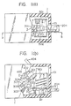
- Fig. 1a
- is a sectional plan view showing an embodiment of the circuit breaker according to the present invention,
- Fig. 1b
- is a sectional side view taken along line b - b in Fig. 1a and showing the state in which the contacts of the circuit breaker are disengaged,
- Fig. 2
- is a sectional side view showing the state in which the contacts of the circuit breaker in Fig. 1b are engaged, and
- Fig. 3
- is a sectional side view showing the state in which the contacts of the circuit breaker in Fig. 1b have started to separate.
- In the drawings, the same symbols indicate identical or corresponding parts.
- Fig. 1a and 1b show an embodiment of the invention wherein an enclosure 1 made of an insulator forms the outer frame of a switching device and is provided with an
exhaust port 101. Afirst contactor 2 ist constructed of a firstrigid conductor 201 which is turnably supported by apivot pin 2b on aholder 2a fixed to the enclosure 1, and afirst contact 202 which is mounted on one end part of the firstrigid conductor 201. The firstrigid conductor 201 is connected to aconnection terminal 204 through aflexible conductor 203. Asecond contactor 3 being movable relative to thefirst contactor 2 in order to close or open the circuit breaker, is constructed of a secondrigid conductor 301 which is operated relative to the firstrigid conductor 201 so as to close or open the circuit breaker, and asecond contact 302 which is mounted on one end part of the secondrigid conductor 301 in manner to confront thefirst contact 202. The secondrigid conductor 301 is connected to an external conductor (not shown) through aflexible conductor 303, and the intermediate part thereof is turnably held on one end part of amovable frame member 304 by apivot pin 305. Across bar 306 is mounted on the other end part of themovable frame member 304 in a direction perpendicular to the plane of the drawing, and acts to move the movable frame member simultaneously in each phase. Atorsion spring 307 is applied to thepivot pin 305 and has its respective end parts held in engagement with the secondrigid conductor 301 and themovable frame member 304. Aspring 2A being interposed between the firstrigid conductor 201 and the enclosure 1 urges thefirst contact 202 against thesecond contact 302. Anoperating mechanism 4 operates thesecond contactor 3 in order to close or open the circuit breaker, and is formed so that one end part of alower link 401 constituting a linkage is turnably coupled to the secondrigid conductor 301 by thepivot pin 305, that one and part of anupper link 402 is turnably coupled to the other end part of thelower link 401 by apivot pin 403, and that an operating handle 414 is turnably coupled to the other end part of theupper link 402 by a pivot pin (not shown). Arc extinguishing plates 5 to extinguish an electric arc struck when thesecond contact 302 is separated from thefirst contact 202 are supported by a pair ofside plates - In addition there are provided
arc shields 6 and 7 made of high resistivity material. Thesearc shields 6, 7 are mounted on the first and secondrigid conductors second contacts arc shields 6, 7 which are plate-shaped pressure reflectors or a covering such as taping and coating. Thesearc shields 6, 7 are made of a substance of a highly resistive material having a resistivity higher than that of a material forming the rigid conductor, thereby to forcibly inject metal particles into an arc space, so that the electrodes are separated at high speed by a high pressure established owing to the provision of the arc shields. As high resistivity material, there can be used, for example, an organic or inorganic insulator, or a high resistivity metal such a copper-nickel, copper-manganese, manganin, iron-carbon, iron-nickel or iron-chromium. It is also possible to use iron whose resistance increases abruptly in accordance with a temperature rise. - When the
operating handle 404 is turned clockwise, the first andsecond contacts rigid conductors rigid conductor 201 is separated a illustrated in Fig. 3, so that the electric arc A develops between the first andsecond contacts operating mechanism 4 works to completely separate the secondrigid conductor 301. Within the arc A itself metal particles of the contacts are reflected by thearc shields 6 and 7 to render the pressure of the arc space high, with the result that the arc is effectively cooled and extinguished. - In accordance with the described embodiment, the first
rigid conductor 201 is turnably held on themovable frame member 304 by thepivot pin 305, whereby in addition thearc shields 6 and 7 are provided. Although theoperating mechanism 4 leads to a low separating speed of the movablerigid conductor 201 on account of its inertia, the pressure of the space Q between thearc shields 6 and 7 becomes very high so that the movablerigid conductor 201 is separated at very high speed without waiting for the drive of theoperating mechanism 4. In consequence, the rise of the arc voltage immediately after the separation is rapid, so that the peak value of the current flowing through the circuit can be suppressed. At the same time there is the effect of narrowing the arc A by thearc shields 6 and 7, so that a high current-limiting effect can be attained. The construction of the circuit breaker is such that, when a comparatively great current flows, no current separation takes place, because the repulsion forces between the first andsecond contacts - In case, that such a circuit breaker is used for alternating currents, the polarity of the current on a contact during arcing is not decided, while the polarity of the arc between the contacts changes even during arcing. In this regard, the circuit breaker of the invention can prevent the polarity effect on the current-limiting performance from becoming different depending upon whether the polarity on the contact to be separated by the electromagnetic repellence is a cathode or an anode, and it can stabilize the current-limiting performance. That is, such beneficial result is achieved by the measure that both the first
rigid conductor 201 and the secondrigid conductor 301 on which thefirst contact 202 and thesecond contact 302 are respectively mounted are formed of the turnable electromagnetic repulsion type.
Claims (6)
- Circuit breaker comprising an operating mechanism (4) to close or open an electric circuit by engaging or disengaging a pair of contacts (202, 302), said pair of contacts (202, 302) being disposed on current conducting conductors (201, 301) of which both of these conductors (201, 301) are pivotally supported in order to be able to move to and from the opposite contact (302, 202) and the first conductor (201) being pivotally mounted on the circuit breaker's enclosure (1) and additionally provided with a spring (2A) urging said first conductor (201) into the direction towards the second conductor (301)
characterized in- that arc shields (6, 7) are disposed on said conductors (201, 301) in a way as to surround said contacts (202, 302)- that said second conductor (301) is provided with a spring (307) loaded pivot (305) and is turnably held to said operating mechanism (4) by said pivot (305) thereby being only supported by said operating mechanism (4) and- that said first conductor (201) and said second conductor (301) are arranged relative to each other in a way that only said contacts (202, 302) and said respective arc shields (6, 7) are facing each other in the closed state. - Circuit breaker according to claim 1, characterized in that both the first and second conductors (201, 301) are connected to external terminals via flexible conductors (203, 303).
- Circuit breaker according to claim 1 or 2, characterized in that at least one of the arc shields (6, 7) is provided with a groove or an arc run way extending from the respective contact (202, 302) towards arc extinguishing plates (5) thereby exposing the respective conductor (201, 301).
- Circuit breaker according to any one of the claims 1-3, characterized in that the arc shields (6, 7) surrounding the peripheries of the first and second contacts (202, 302) and concealing parts of the first and second conductors (201, 301) adjacent to these contacts (202, 302) are made of high resistivity materials.
- Circuit breaker according to claim 4, characterized in that the high resistivity material of the arc shields (6, 7) is an organic or inorganic insulator.
- Circuit breaker according to claim 4, characterized in that the high-resistivity material of the arc shields (6, 7) is a high resistivity metal such as copper-nickel, copper-manganese, manganin, iron-carbon, iron-nickel, iron-chromium or iron.
Priority Applications (1)
| Application Number | Priority Date | Filing Date | Title |
|---|---|---|---|
| EP86115277A EP0232473B1 (en) | 1981-03-12 | 1982-03-12 | A circuit breaker |
Applications Claiming Priority (11)
| Application Number | Priority Date | Filing Date | Title |
|---|---|---|---|
| JP35554/81U | 1981-03-12 | ||
| JP1981035554U JPH0218516Y2 (en) | 1981-03-12 | 1981-03-12 | |
| JP35557/81U | 1981-03-12 | ||
| JP3555281U JPS57147548U (en) | 1981-03-12 | 1981-03-12 | |
| JP35552/81U | 1981-03-12 | ||
| JP3555681U JPS57147552U (en) | 1981-03-12 | 1981-03-12 | |
| JP35556/81U | 1981-03-12 | ||
| JP35555/81U | 1981-03-12 | ||
| JP3555581U JPS57147551U (en) | 1981-03-12 | 1981-03-12 | |
| JP3555781U JPS57147553U (en) | 1981-03-12 | 1981-03-12 | |
| EP86115277A EP0232473B1 (en) | 1981-03-12 | 1982-03-12 | A circuit breaker |
Related Parent Applications (1)
| Application Number | Title | Priority Date | Filing Date |
|---|---|---|---|
| EP82102015.3 Division | 1982-03-12 |
Publications (3)
| Publication Number | Publication Date |
|---|---|
| EP0232473A2 EP0232473A2 (en) | 1987-08-19 |
| EP0232473A3 EP0232473A3 (en) | 1987-09-09 |
| EP0232473B1 true EP0232473B1 (en) | 1991-05-29 |
Family
ID=27545382
Family Applications (1)
| Application Number | Title | Priority Date | Filing Date |
|---|---|---|---|
| EP86115277A Expired - Lifetime EP0232473B1 (en) | 1981-03-12 | 1982-03-12 | A circuit breaker |
Country Status (1)
| Country | Link |
|---|---|
| EP (1) | EP0232473B1 (en) |
Citations (1)
| Publication number | Priority date | Publication date | Assignee | Title |
|---|---|---|---|---|
| DE2928823A1 (en) * | 1978-08-10 | 1980-02-21 | Fuji Electric Co Ltd | Automatic protective circuit breaker - has stationary and moving contacts parallel in closed state and sliding pin for sprung stationary contact |
Family Cites Families (5)
| Publication number | Priority date | Publication date | Assignee | Title |
|---|---|---|---|---|
| US3127488A (en) * | 1960-07-18 | 1964-03-31 | Ite Circuit Breaker Ltd | Current limiting circuit breaker having both contacts movable |
| US3402273A (en) * | 1965-12-01 | 1968-09-17 | Ite Circuit Breaker Ltd | Arc chamber for circuit breakers |
| DE1765050B2 (en) * | 1968-03-26 | 1976-08-05 | Deutsche Gold- Und Silber-Scheideanstalt Vormals Roessler, 6000 Frankfurt | ELECTRICAL CONTACT OR ELECTRODE ARRANGEMENT FOR THE FIXED STABILIZATION OF THE ARC FLOOR POINTS AND TO REDUCE THE BURN-ON LOSS |
| US3997746A (en) * | 1974-04-23 | 1976-12-14 | Airpax Electronics, Incorporated | Circuit breaker with arc chamber screen |
| US4409445A (en) * | 1980-12-09 | 1983-10-11 | Mitsubishi Denki Kabushiki Kaisha | Circuit breaker |
-
1982
- 1982-03-12 EP EP86115277A patent/EP0232473B1/en not_active Expired - Lifetime
Patent Citations (1)
| Publication number | Priority date | Publication date | Assignee | Title |
|---|---|---|---|---|
| DE2928823A1 (en) * | 1978-08-10 | 1980-02-21 | Fuji Electric Co Ltd | Automatic protective circuit breaker - has stationary and moving contacts parallel in closed state and sliding pin for sprung stationary contact |
Also Published As
| Publication number | Publication date |
|---|---|
| EP0232473A2 (en) | 1987-08-19 |
| EP0232473A3 (en) | 1987-09-09 |
Similar Documents
| Publication | Publication Date | Title |
|---|---|---|
| US5495083A (en) | Electric switch device with separable contacts including fixed contact mounted current limiter and shunt conductor | |
| US5877467A (en) | Circuit breaker current limiting arc runner | |
| US4654491A (en) | Circuit breaker with contact support and arc runner | |
| EP0059476B1 (en) | Circuit breaker | |
| CA1085437A (en) | Circuit breaker having improved line strap construction | |
| DE3066807D1 (en) | Electrical switchgear of the rotating arc, double-break type | |
| JPH02119018A (en) | circuit breaker | |
| EP0288040B1 (en) | Circuit Breaker | |
| EP0059475B1 (en) | A current limiter | |
| EP0233322B1 (en) | A circuit breaker | |
| EP0233323B1 (en) | A circuit breaker | |
| EP0237623B1 (en) | A circuit breaker | |
| EP0054833A1 (en) | Arc restricting device for a circuit breaker | |
| CA1217525A (en) | Insulated latch-cradle mechanism | |
| US4309580A (en) | Dual arcing contacts for circuit breaker | |
| EP0059455B2 (en) | Arc restricting device for circuit breaker | |
| US4598187A (en) | Current limiting circuit breaker | |
| EP0061097B1 (en) | Circuit breaker | |
| US5874873A (en) | Electric control apparatus | |
| US5189384A (en) | Circuit breaker having improved contact structure | |
| US4698607A (en) | High speed contact driver for circuit interruption device | |
| JPH0472327B2 (en) | ||
| US4656324A (en) | Current limiting circuit interrupter | |
| JP2793182B2 (en) | Circuit breakers and breakers | |
| EP0232473A2 (en) | A circuit breaker |
Legal Events
| Date | Code | Title | Description |
|---|---|---|---|
| PUAI | Public reference made under article 153(3) epc to a published international application that has entered the european phase |
Free format text: ORIGINAL CODE: 0009012 |
|
| PUAL | Search report despatched |
Free format text: ORIGINAL CODE: 0009013 |
|
| AC | Divisional application: reference to earlier application |
Ref document number: 61097 Country of ref document: EP |
|
| AK | Designated contracting states |
Kind code of ref document: A2 Designated state(s): CH DE FR GB IT LI |
|
| AK | Designated contracting states |
Kind code of ref document: A3 Designated state(s): CH DE FR GB IT LI |
|
| 17P | Request for examination filed |
Effective date: 19880226 |
|
| 17Q | First examination report despatched |
Effective date: 19900410 |
|
| GRAA | (expected) grant |
Free format text: ORIGINAL CODE: 0009210 |
|
| AC | Divisional application: reference to earlier application |
Ref document number: 61097 Country of ref document: EP |
|
| AK | Designated contracting states |
Kind code of ref document: B1 Designated state(s): CH DE FR GB IT LI |
|
| ITF | It: translation for a ep patent filed | ||
| REF | Corresponds to: |
Ref document number: 3280339 Country of ref document: DE Date of ref document: 19910704 |
|
| ET | Fr: translation filed | ||
| PLBE | No opposition filed within time limit |
Free format text: ORIGINAL CODE: 0009261 |
|
| STAA | Information on the status of an ep patent application or granted ep patent |
Free format text: STATUS: NO OPPOSITION FILED WITHIN TIME LIMIT |
|
| 26N | No opposition filed | ||
| PGFP | Annual fee paid to national office [announced via postgrant information from national office to epo] |
Ref country code: CH Payment date: 19950315 Year of fee payment: 14 |
|
| REG | Reference to a national code |
Ref country code: GB Ref legal event code: 746 Effective date: 19951026 |
|
| REG | Reference to a national code |
Ref country code: FR Ref legal event code: D6 |
|
| PG25 | Lapsed in a contracting state [announced via postgrant information from national office to epo] |
Ref country code: LI Effective date: 19960331 Ref country code: CH Effective date: 19960331 |
|
| ITPR | It: changes in ownership of a european patent |
Owner name: OFFERTA DI LICENZA AL PUBBLICO |
|
| REG | Reference to a national code |
Ref country code: CH Ref legal event code: PL |
|
| PGFP | Annual fee paid to national office [announced via postgrant information from national office to epo] |
Ref country code: FR Payment date: 19990309 Year of fee payment: 18 |
|
| PGFP | Annual fee paid to national office [announced via postgrant information from national office to epo] |
Ref country code: GB Payment date: 19990311 Year of fee payment: 18 |
|
| PGFP | Annual fee paid to national office [announced via postgrant information from national office to epo] |
Ref country code: DE Payment date: 19990319 Year of fee payment: 18 |
|
| PG25 | Lapsed in a contracting state [announced via postgrant information from national office to epo] |
Ref country code: GB Free format text: LAPSE BECAUSE OF NON-PAYMENT OF DUE FEES Effective date: 20000312 |
|
| GBPC | Gb: european patent ceased through non-payment of renewal fee |
Effective date: 20000312 |
|
| PG25 | Lapsed in a contracting state [announced via postgrant information from national office to epo] |
Ref country code: FR Free format text: LAPSE BECAUSE OF NON-PAYMENT OF DUE FEES Effective date: 20001130 |
|
| REG | Reference to a national code |
Ref country code: FR Ref legal event code: ST |
|
| PG25 | Lapsed in a contracting state [announced via postgrant information from national office to epo] |
Ref country code: DE Free format text: LAPSE BECAUSE OF NON-PAYMENT OF DUE FEES Effective date: 20010103 |