EP0231962A1 - Heater with tap water supply and a heat exchanger for such a heater - Google Patents
Heater with tap water supply and a heat exchanger for such a heater Download PDFInfo
- Publication number
- EP0231962A1 EP0231962A1 EP87200042A EP87200042A EP0231962A1 EP 0231962 A1 EP0231962 A1 EP 0231962A1 EP 87200042 A EP87200042 A EP 87200042A EP 87200042 A EP87200042 A EP 87200042A EP 0231962 A1 EP0231962 A1 EP 0231962A1
- Authority
- EP
- European Patent Office
- Prior art keywords
- pipe
- tap water
- connecting parts
- heater
- heat exchanger
- Prior art date
- Legal status (The legal status is an assumption and is not a legal conclusion. Google has not performed a legal analysis and makes no representation as to the accuracy of the status listed.)
- Withdrawn
Links
- 239000008399 tap water Substances 0.000 title claims abstract description 51
- 235000020679 tap water Nutrition 0.000 title claims abstract description 51
- 238000010438 heat treatment Methods 0.000 claims abstract description 24
- 239000003546 flue gas Substances 0.000 claims abstract description 19
- 238000002485 combustion reaction Methods 0.000 claims abstract description 12
- RYGMFSIKBFXOCR-UHFFFAOYSA-N Copper Chemical compound [Cu] RYGMFSIKBFXOCR-UHFFFAOYSA-N 0.000 claims description 13
- 229910052802 copper Inorganic materials 0.000 claims description 13
- 239000010949 copper Substances 0.000 claims description 13
- 229910000838 Al alloy Inorganic materials 0.000 claims description 6
- 229910052782 aluminium Inorganic materials 0.000 description 5
- XAGFODPZIPBFFR-UHFFFAOYSA-N aluminium Chemical compound [Al] XAGFODPZIPBFFR-UHFFFAOYSA-N 0.000 description 5
- 238000010276 construction Methods 0.000 description 4
- XLYOFNOQVPJJNP-UHFFFAOYSA-N water Substances O XLYOFNOQVPJJNP-UHFFFAOYSA-N 0.000 description 4
- 238000009833 condensation Methods 0.000 description 3
- 230000005494 condensation Effects 0.000 description 3
- 230000007704 transition Effects 0.000 description 2
- QVGXLLKOCUKJST-UHFFFAOYSA-N atomic oxygen Chemical compound [O] QVGXLLKOCUKJST-UHFFFAOYSA-N 0.000 description 1
- 230000007797 corrosion Effects 0.000 description 1
- 238000005260 corrosion Methods 0.000 description 1
- 239000000463 material Substances 0.000 description 1
- 229910052751 metal Inorganic materials 0.000 description 1
- 239000002184 metal Substances 0.000 description 1
- 150000002739 metals Chemical class 0.000 description 1
- 239000001301 oxygen Substances 0.000 description 1
- 229910052760 oxygen Inorganic materials 0.000 description 1
- 230000000717 retained effect Effects 0.000 description 1
- 238000007789 sealing Methods 0.000 description 1
Images


Classifications
-
- F—MECHANICAL ENGINEERING; LIGHTING; HEATING; WEAPONS; BLASTING
- F28—HEAT EXCHANGE IN GENERAL
- F28D—HEAT-EXCHANGE APPARATUS, NOT PROVIDED FOR IN ANOTHER SUBCLASS, IN WHICH THE HEAT-EXCHANGE MEDIA DO NOT COME INTO DIRECT CONTACT
- F28D15/00—Heat-exchange apparatus with the intermediate heat-transfer medium in closed tubes passing into or through the conduit walls ; Heat-exchange apparatus employing intermediate heat-transfer medium or bodies
-
- F—MECHANICAL ENGINEERING; LIGHTING; HEATING; WEAPONS; BLASTING
- F24—HEATING; RANGES; VENTILATING
- F24H—FLUID HEATERS, e.g. WATER OR AIR HEATERS, HAVING HEAT-GENERATING MEANS, e.g. HEAT PUMPS, IN GENERAL
- F24H1/00—Water heaters, e.g. boilers, continuous-flow heaters or water-storage heaters
- F24H1/48—Water heaters for central heating incorporating heaters for domestic water
- F24H1/52—Water heaters for central heating incorporating heaters for domestic water incorporating heat exchangers for domestic water
- F24H1/526—Pipes in pipe heat exchangers for sanitary water
-
- F—MECHANICAL ENGINEERING; LIGHTING; HEATING; WEAPONS; BLASTING
- F24—HEATING; RANGES; VENTILATING
- F24H—FLUID HEATERS, e.g. WATER OR AIR HEATERS, HAVING HEAT-GENERATING MEANS, e.g. HEAT PUMPS, IN GENERAL
- F24H8/00—Fluid heaters characterised by means for extracting latent heat from flue gases by means of condensation
-
- F—MECHANICAL ENGINEERING; LIGHTING; HEATING; WEAPONS; BLASTING
- F28—HEAT EXCHANGE IN GENERAL
- F28D—HEAT-EXCHANGE APPARATUS, NOT PROVIDED FOR IN ANOTHER SUBCLASS, IN WHICH THE HEAT-EXCHANGE MEDIA DO NOT COME INTO DIRECT CONTACT
- F28D7/00—Heat-exchange apparatus having stationary tubular conduit assemblies for both heat-exchange media, the media being in contact with different sides of a conduit wall
- F28D7/0066—Multi-circuit heat-exchangers, e.g. integrating different heat exchange sections in the same unit or heat-exchangers for more than two fluids
-
- F—MECHANICAL ENGINEERING; LIGHTING; HEATING; WEAPONS; BLASTING
- F28—HEAT EXCHANGE IN GENERAL
- F28F—DETAILS OF HEAT-EXCHANGE AND HEAT-TRANSFER APPARATUS, OF GENERAL APPLICATION
- F28F1/00—Tubular elements; Assemblies of tubular elements
- F28F1/10—Tubular elements and assemblies thereof with means for increasing heat-transfer area, e.g. with fins, with projections, with recesses
- F28F1/12—Tubular elements and assemblies thereof with means for increasing heat-transfer area, e.g. with fins, with projections, with recesses the means being only outside the tubular element
- F28F1/34—Tubular elements and assemblies thereof with means for increasing heat-transfer area, e.g. with fins, with projections, with recesses the means being only outside the tubular element and extending obliquely
- F28F1/36—Tubular elements and assemblies thereof with means for increasing heat-transfer area, e.g. with fins, with projections, with recesses the means being only outside the tubular element and extending obliquely the means being helically wound fins or wire spirals
-
- F—MECHANICAL ENGINEERING; LIGHTING; HEATING; WEAPONS; BLASTING
- F28—HEAT EXCHANGE IN GENERAL
- F28F—DETAILS OF HEAT-EXCHANGE AND HEAT-TRANSFER APPARATUS, OF GENERAL APPLICATION
- F28F9/00—Casings; Header boxes; Auxiliary supports for elements; Auxiliary members within casings
- F28F9/26—Arrangements for connecting different sections of heat-exchange elements, e.g. of radiators
-
- Y—GENERAL TAGGING OF NEW TECHNOLOGICAL DEVELOPMENTS; GENERAL TAGGING OF CROSS-SECTIONAL TECHNOLOGIES SPANNING OVER SEVERAL SECTIONS OF THE IPC; TECHNICAL SUBJECTS COVERED BY FORMER USPC CROSS-REFERENCE ART COLLECTIONS [XRACs] AND DIGESTS
- Y02—TECHNOLOGIES OR APPLICATIONS FOR MITIGATION OR ADAPTATION AGAINST CLIMATE CHANGE
- Y02B—CLIMATE CHANGE MITIGATION TECHNOLOGIES RELATED TO BUILDINGS, e.g. HOUSING, HOUSE APPLIANCES OR RELATED END-USER APPLICATIONS
- Y02B30/00—Energy efficient heating, ventilation or air conditioning [HVAC]
Definitions
- the present invention relates to a heater with tap water supply, comprising a combustion chamber being provided with a burner and having an outlet for the flue gases, and in which combustion chamber is fitted a heat exchanger for a heating medium, which consists of a number of parallel pipe lengths extending between two opposite walls of the combustion chamber and are connected to each other by means of connecting parts which form chambers, and successively are flowed through by the heating medium, while a number of these pipe lengths are provided with a pipe for tap water which extends coaxially herein, said pipes for tap water being connected together to form a throughgoing channel which is connected at one side to an infeed and at the other side to a discharge for tap water.
- the object of the invention is to produce a heater in which the problem outlined above is avoided in a practical manner, and which also ensures good heat transfer both to the heating medium and to the tap water.
- Another object of the invention is to produce a heater of a compact structure which is easy to produce and assemble.
- Each pipe length which contains a pipe for tap water, preferably consists of a thick-walled pipe part which is provided with external ribs and has a central passage which forms the pipe for the tap water, the pipe part having at both ends a thin-walled part with smaller diameter, and provision being made in the thick-walled part for a number of axial channels for the heating medium, which debouch on the outer periphery of the thin-walled parts into the chambers of the connecting parts connected thereto, while the thin-walled parts extend right through the connecting parts.
- This construction has the advantage that both the heating medium and the tap water are heated directly through the wall of the pipe length, so that good heat transfer is ensured to both media.
- each pipe length is made of an aluminum alloy, and the pipe for the tap water is provided with an internal copper lining.
- the pipes forming the channel for the tap water are thus designed as bimetal pipes, so that the problem of corrosion of the aluminum does not occur.
- the connecting pieces between the pipes can now consist of copper bends, since these bends are not in contact with the aluminum through heating medium.
- the infeed for tap water is connected to the pipe for tap water which is situated inside the pipe length which last comes into contact with the flue gases.
- the invention is also embodied in a heat exchanger which is characterized in that it consists of a number of thick-walled parallel pipe lengths which are connected to each other by connecting parts which form chambers and each have in their wall one or more axial passages which debouch into the chambers of the connecting parts connecting hereto, and the central passage of each pipe which forms a channel for tap water is extended beyond the connecting parts, and said passages are connected together.
- Figure 1 shows schematically a heater 1, comprising a combustion chamber 2, in which are fitted a burner 3 and a heat exchanger 4 for a heating medium.
- the combustion chamber also has an outlet 5 for the flue gases.
- the heat exchanger 4 consists of a number of parallel pipe lengths 6, 6′, provided with ribs 7 on the outside.
- the pipe lengths are connected to each other by means of connecting parts 8, 8′ and are flowed through in succession by the heating medium in such a way that the cold heating medium enters the heat exchanger through the pipe lengths which last come into contact with the flue gases.
- the heat exchanger 4 for heating medium is combined with a heat exchanger 9 for the tap water.
- the heat exchanger 9 is formed by a pipe part 10, 10′ inside each pipe length 6, 6′, so that two channels are produced in each pipe length.
- the outermost channel is here flowed through by heating medium and the central channel by tap of service water.
- the various pipe parts are connected to each other by bends 11.
- the pipe parts 10, 10′ are provided on the outside with ribs 12, which in Figure 1 run transversely to the lengthwise direction of the pipe parts, but which can also extend in the lengthwise direction thereof, as shown in Figures 2 and 3.
- Figures 2 and 3 show an end of the pipe length 6, which is connected to the connecting part 8, which connecting part can be incorporated in the wall of the combustion chamber.
- the end of the pipe length 6 is sealed off from the connecting part 8 by means of an O-ring 13.
- the pipe part 10 for the tap water runs concentrically inside the pipe length 6 and is taken to the outside through an opening 14 in the connecting part 8, in which opening a sealing ring 15 is fitted.
- the pipe part 10 is provided with ribs 12 extending radially in the lengthwise direction of the pipe part, while the ribs 7 on the outside of the pipe length 6 run helically.
- the pipe parts 10, 10′ of the heat exchanger for tap water consist of a copper inner tube with connected around it an outside of an aluminum alloy. This construction meets the requirement that the pipe for tap water must be of copper, and aluminum and copper are incompatible in an oxygen-rich environment, due to a potential difference between the two metals.
- the cold heating medium comes into the heat exchanger 4 through the pipe parts of the heat exchanger which were last in contact with the flue gases.
- the advantage of this is that the flue gases can be cooled down to below their condensation temperature. Consequently, the infeed of cold tap water into the heat exchanger 9 is into the pipe part of this heat exchanger which are situated in the pipe length of the heat exchanger 4 which are last in contact with the flue gases.
- the heating medium and the tap water run through the pipe lengths in the same or almost the same sequence. If the heater is now used only for drawing hot water, the flue gases can also be cooled down to below their condensation temperature, so that the "high-efficiency" action of the heater also applies when it is being used as a geyser.
- FIGS 4 and 5 show another embodiment of the heater according to the invention.
- the heat exchanger instead of the heat exchanger made up of concentric pipes, the heat exchanger here consists of a number of parallel thick-walled pipe parts 16, 16′ and 16′′ which are provided on the outer periphery with helical ribs 17.
- each pipe length 16, 16′, 16′′ Disposed in the wall of each pipe length 16, 16′, 16′′ are a number of passages 18 extending in the lengthwise direction of the pipe length, and lying at regular intervals from each other.
- the passages 18 together form the channel for the heating medium in each pipe length.
- each pipe length narrows at both ends by means of a tapering transition part 19 to a thin-walled part 20.
- the passages 18 debouch at the tapering transition part 19.
- the pipe lengths 16, 16′ and 16′′ are connected to each other by means of connecting parts 21 forming chambers and connecting together the passages 18 of two pipe lengths flowed through successively.
- the thin-walled part 20 of each pipe length runs through the connecting part and is sealed off from it by an O-ring 22.
- the central passage of the thick-walled pipe length which is intended for the passage of tap or utility water, is provided with a copper lining 23, which is rolled into the pipe length.
- the central passages of two pipe lengths flowed through successively are connected together by a copper bend 24 which thus lies outside the connecting part.
- This construction means that there is no contact either via the heating medium or via the tap water between the copper of the pipe for tap water and the aluminum alloy of the pipe lengths.
- the pipe lengths are always placed side by side in one plane, and the heating medium and the tap water can run through each pipe length in countercurrent.
- the pipe lengths are preferably arranged in several planes running parallel to each other.
- the flue gases pass through the heat exchanger in the direction of the arrows A.
- a guide block 25 Disposed between the walls of the combustion chamber and the adjoining pipe length is a guide block 25, while guide blocks 26 are also disposed between each of the pipe lengths. The purpose of these blocks is to guide the flue gases between the ribs 17 of the pipe lengths, in order to ensure optimum heat transfer.
- the heat from the flue gases is transferred via the thick wall both directly to the heating medium flowing in the passages 18 and directly to tap water flowing through the cenral channel, so that good heat transfer is always ensured to both media, while the compact structure of the heat exchanger is retained.
Landscapes
- Engineering & Computer Science (AREA)
- Physics & Mathematics (AREA)
- Thermal Sciences (AREA)
- Mechanical Engineering (AREA)
- General Engineering & Computer Science (AREA)
- Chemical & Material Sciences (AREA)
- Combustion & Propulsion (AREA)
- Geometry (AREA)
- Health & Medical Sciences (AREA)
- Public Health (AREA)
- Details Of Fluid Heaters (AREA)
- Heat-Exchange Devices With Radiators And Conduit Assemblies (AREA)
Abstract
The invention relates to a heater with tap water supply, comprising a combustion chamber (2) being provided with a burner (3) and having an outlet (5) for the flue gases. In said combustion chamber is arranged a heat exchanger (4) for a heating medium, consisting of a number of parallel pipe lengths, which are connected to each other by means of connecting parts (8, 8′). Some of the pipe lengths are provided with a pipe (10, 10′) for tap water which extends coaxially herein. The pipes for tap water are connected together to form a channel for tap water to be heated. Said pipes for tap water lying coaxially inside the respective pipe lengths each extend right through the connecting parts and are sealed off relative said connecting parts, said pipes being connected to each other outside the connecting parts. The invention also relates to a heat exchanger for such a heater, in which each pipe length which contains a pipe for tap water consists of a thick-walled pipe part having a central passage (23) for tap water and axial channels (18) in the thick wall for heating medium.
Description
- The present invention relates to a heater with tap water supply, comprising a combustion chamber being provided with a burner and having an outlet for the flue gases, and in which combustion chamber is fitted a heat exchanger for a heating medium, which consists of a number of parallel pipe lengths extending between two opposite walls of the combustion chamber and are connected to each other by means of connecting parts which form chambers, and successively are flowed through by the heating medium, while a number of these pipe lengths are provided with a pipe for tap water which extends coaxially herein, said pipes for tap water being connected together to form a throughgoing channel which is connected at one side to an infeed and at the other side to a discharge for tap water.
- The problem occurring with such heaters is the complex structure of the heat exchanger, since the heat exchanger for the tap water is in fact integrated in the heat exchanger for the heating medium. This problem is all the more important since parts of the heat exchanger coming into contact with flue gases are made of an aluminum alloy, while the pipes for the tap water must be made of copper. The presence of copper in the vicinity of aluminum in an oxygen-rich environment causes the aluminum to be affected (dissolved), as a result of the potential difference between the two materials.
- The object of the invention is to produce a heater in which the problem outlined above is avoided in a practical manner, and which also ensures good heat transfer both to the heating medium and to the tap water.
- Another object of the invention is to produce a heater of a compact structure which is easy to produce and assemble.
- The above objects are achieved according to the invention through the fact that the pipes for tap water lying coaxially inside the particular pipe lengths each extend right through the connecting parts, said pipes being connected to each other outside the connecting parts.
- Through the fact that the pipes for the tap water run through to the outside of the connecting parts, these pipes can easily be connected to each other, in which case the connecting parts do not come into contact with the heating medium.
- Each pipe length, which contains a pipe for tap water, preferably consists of a thick-walled pipe part which is provided with external ribs and has a central passage which forms the pipe for the tap water, the pipe part having at both ends a thin-walled part with smaller diameter, and provision being made in the thick-walled part for a number of axial channels for the heating medium, which debouch on the outer periphery of the thin-walled parts into the chambers of the connecting parts connected thereto, while the thin-walled parts extend right through the connecting parts.
- This construction has the advantage that both the heating medium and the tap water are heated directly through the wall of the pipe length, so that good heat transfer is ensured to both media.
- According to the invention, each pipe length is made of an aluminum alloy, and the pipe for the tap water is provided with an internal copper lining. The pipes forming the channel for the tap water are thus designed as bimetal pipes, so that the problem of corrosion of the aluminum does not occur. The connecting pieces between the pipes can now consist of copper bends, since these bends are not in contact with the aluminum through heating medium.
- In order to be able also to cool the flue gases to below their condensation temperature when the heater is working only as a hot water supply, according to the invention the infeed for tap water is connected to the pipe for tap water which is situated inside the pipe length which last comes into contact with the flue gases.
- In this way, during the drawing of tap water a geyser is produced which cools the flue gases to below dew point, so that one could speak of a "high-efficiency geyser".
- The invention is also embodied in a heat exchanger which is characterized in that it consists of a number of thick-walled parallel pipe lengths which are connected to each other by connecting parts which form chambers and each have in their wall one or more axial passages which debouch into the chambers of the connecting parts connecting hereto, and the central passage of each pipe which forms a channel for tap water is extended beyond the connecting parts, and said passages are connected together.
- The invention is explained in greater detail with reference to the drawing, in which:
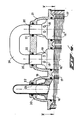
- Figure 1 shows schematically a heater according to the present invention;
- Figure 2 shows a detail of the heater of Figure 1;
- Figure 3 shows a view according to line III-III in figure 2;
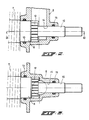
- Figure 4 shows a cross section of part of another embodiment of the heat exchanger according to the invention;
- Figure 5 shows a cross section along the line V-V in figure 4;
- Figure 1 shows schematically a
heater 1, comprising acombustion chamber 2, in which are fitted a burner 3 and aheat exchanger 4 for a heating medium. The combustion chamber also has anoutlet 5 for the flue gases. - The
heat exchanger 4 consists of a number ofparallel pipe lengths ribs 7 on the outside. The pipe lengths are connected to each other by means of connectingparts - The
heat exchanger 4 for heating medium is combined with a heat exchanger 9 for the tap water. The heat exchanger 9 is formed by apipe part pipe length bends 11. - The
pipe parts ribs 12, which in Figure 1 run transversely to the lengthwise direction of the pipe parts, but which can also extend in the lengthwise direction thereof, as shown in Figures 2 and 3. - The
bend 11, which connects twoparallel pipe parts part 8 of thepipe lengths heat exchanger 4. This means that thepipe parts part 8, and the design thereof is shown in greater detail in Figures 2 and 3. - Figures 2 and 3 show an end of the
pipe length 6, which is connected to the connectingpart 8, which connecting part can be incorporated in the wall of the combustion chamber. The end of thepipe length 6 is sealed off from the connectingpart 8 by means of an O-ring 13. Thepipe part 10 for the tap water runs concentrically inside thepipe length 6 and is taken to the outside through an opening 14 in the connectingpart 8, in which opening asealing ring 15 is fitted. - In the embodiment shown in Figures 2 and 3, the
pipe part 10 is provided withribs 12 extending radially in the lengthwise direction of the pipe part, while theribs 7 on the outside of thepipe length 6 run helically. - The
pipe parts - As already said above, the cold heating medium comes into the
heat exchanger 4 through the pipe parts of the heat exchanger which were last in contact with the flue gases. The advantage of this is that the flue gases can be cooled down to below their condensation temperature. Consequently, the infeed of cold tap water into the heat exchanger 9 is into the pipe part of this heat exchanger which are situated in the pipe length of theheat exchanger 4 which are last in contact with the flue gases. In other words, the heating medium and the tap water run through the pipe lengths in the same or almost the same sequence. If the heater is now used only for drawing hot water, the flue gases can also be cooled down to below their condensation temperature, so that the "high-efficiency" action of the heater also applies when it is being used as a geyser. - By means of the construction according to the invention one thus obtains not only a simple and compact unit, but also a "high-efficiency" tap water supply.
- Figures 4 and 5 show another embodiment of the heater according to the invention. Instead of the heat exchanger made up of concentric pipes, the heat exchanger here consists of a number of parallel thick-
walled pipe parts helical ribs 17. - Disposed in the wall of each
pipe length passages 18 extending in the lengthwise direction of the pipe length, and lying at regular intervals from each other. Thepassages 18 together form the channel for the heating medium in each pipe length. - The wall of each pipe length narrows at both ends by means of a
tapering transition part 19 to a thin-walled part 20. Thepassages 18 debouch at thetapering transition part 19. Thepipe lengths parts 21 forming chambers and connecting together thepassages 18 of two pipe lengths flowed through successively. The thin-walled part 20 of each pipe length runs through the connecting part and is sealed off from it by an O-ring 22. - The central passage of the thick-walled pipe length, which is intended for the passage of tap or utility water, is provided with a
copper lining 23, which is rolled into the pipe length. The central passages of two pipe lengths flowed through successively are connected together by acopper bend 24 which thus lies outside the connecting part. This construction means that there is no contact either via the heating medium or via the tap water between the copper of the pipe for tap water and the aluminum alloy of the pipe lengths. - As can be seen more clearly from Figure 5, the pipe lengths are always placed side by side in one plane, and the heating medium and the tap water can run through each pipe length in countercurrent. The pipe lengths are preferably arranged in several planes running parallel to each other. The flue gases pass through the heat exchanger in the direction of the arrows A.
- Disposed between the walls of the combustion chamber and the adjoining pipe length is a
guide block 25, whileguide blocks 26 are also disposed between each of the pipe lengths. The purpose of these blocks is to guide the flue gases between theribs 17 of the pipe lengths, in order to ensure optimum heat transfer. - The heat from the flue gases is transferred via the thick wall both directly to the heating medium flowing in the
passages 18 and directly to tap water flowing through the cenral channel, so that good heat transfer is always ensured to both media, while the compact structure of the heat exchanger is retained. - It will be clear that within the scope of the invention a large number of variants are possible as regards the number and arrangement of the concentric pipe parts and the connections between them.
Claims (8)
1. Heater (1) with tap water supply, comprising a combustion chamber (2) being provided with a burner (3) and having an outlet (5) for the flue gases, and in which combustion chamber is fitted a heat exchanger (4) for a heating medium, which consists of a number of parallel pipe lengths (6, 6′) extending between two opposite walls of the combustion chamber and being connected to each other by means of connecting parts (8, 8′) which form chambers, said pipe lengths being successively flowed through by the heating medium, while a number of these pipe lengths are provided with a pipe (10, 10′) for tap water which extends coaxially herein, said pipes for tap water being connected together to form a throughgoing channel which is connected at one side to an infeed and at the other side to a discharge for tap water, characterized in that the pipes for tap water lying coaxially inside the particular pipe lengths each extend right through the connecting parts (8, 8′) and are sealed off relative to said connecting parts, said pipes being connected to each other outside the connecting parts.
2. Heater acccording to Claim 1, characterized in that each pipe length, which contains a pipe for tap water, consists of a thick-walled pipe part (16, 16′, 16′′) which is provided with external ribs (17, 17′, 17′′) and has a central passage (23) which forms the channel for the tap water, the pipe part having at both ends a thin-walled part (20) with smaller diameter, and provision being made in the thick-walled part for a number of axial channels (18) for the heating medium, which debouch on the outer periphery of the thin-walled parts into the chambers of the connecting parts (21) connected thereto, while the thin-walled parts extend right through said connecting parts.
3. Heater according to Claim 1, characterized in that each pipe length consists of a pipe provided externally with ribs (7), with a pipe for tap water lying coaxially herein, which is provided on the outer periphery with ribs (12) and always extends beyond the connecting parts (8, 8′).
4. Heater according to Claim 1, 2 or 3, characterized in that each pipe length (6, 6′; 16, 16′, 16′′) is made of an aluminum alloy, and the pipe for the tap water is provided with an internal copper lining.
5. Heater according to one or more of the preceding Claims, characterized in that the infeed for tap water is connected to the pipe for tap water which is situated inside the pipe length which last comes into contact with the flue gases.
6. Heater according to one or more of the preceding Claims 1-5, characterized in that the pipe lengths are arranged in one or more planes running parallel to each other and guide blocks (26) are disposed at least between the pipe lengths situated in the plane last flowed through by the flue gases, for the purpose of forcing the flue gases between the ribs of the pipe lengths.
7. Heat exchanger for a heater according to one or more of the preceding Claims 1-6, characterized in that it consists of a number of thick-walled parallel pipe lengths (16, 16′, 16′′) which are connected to each other by connecting parts (21) which form chambers and said pipe lengths have in their wall one or more axial passages (18) which debouch into the chambers of the connecting parts connecting hereto, and the central passage of each pipe which forms a channel for tap water is extended beyond the connecting parts, and said passages are connected together.
8. Heat exchanger according to Claim 7, characterized in that each pipe length is made of an aluminum alloy and the pipe for tap water is provided with an internal copper lining, and the various pipes for tap water are connected together by copper bends (24).
Applications Claiming Priority (4)
| Application Number | Priority Date | Filing Date | Title |
|---|---|---|---|
| NL8600108 | 1986-01-20 | ||
| NL8600108A NL8600108A (en) | 1986-01-20 | 1986-01-20 | Direct fired water heater - has heat exchanger with water tubes connected externally to unit |
| NL8602966 | 1986-11-21 | ||
| NL8602966A NL8602966A (en) | 1986-01-20 | 1986-11-21 | BOILER WITH DHW SUPPLY AND A HEAT EXCHANGER FOR SUCH A BOILER. |
Publications (1)
| Publication Number | Publication Date |
|---|---|
| EP0231962A1 true EP0231962A1 (en) | 1987-08-12 |
Family
ID=26646105
Family Applications (1)
| Application Number | Title | Priority Date | Filing Date |
|---|---|---|---|
| EP87200042A Withdrawn EP0231962A1 (en) | 1986-01-20 | 1987-01-14 | Heater with tap water supply and a heat exchanger for such a heater |
Country Status (2)
| Country | Link |
|---|---|
| EP (1) | EP0231962A1 (en) |
| NL (1) | NL8602966A (en) |
Cited By (7)
| Publication number | Priority date | Publication date | Assignee | Title |
|---|---|---|---|---|
| WO2002050478A1 (en) * | 2000-12-20 | 2002-06-27 | Merloni Termosanitari S.P.A. | Bi-thermal heat exchanger in particular for condensing boilers |
| WO2006097959A1 (en) * | 2005-03-15 | 2006-09-21 | Tec.Lab. S.C.R.L. | Heat exchanger for condensing wall-mounted boilers |
| CN101852566A (en) * | 2010-05-10 | 2010-10-06 | 赵春 | Horizontal combined phase change heat exchanger |
| ITMI20100590A1 (en) * | 2010-04-08 | 2011-10-09 | Riello Spa | HEAT EXCHANGER TO HEAT AT LEAST TWO LIQUIDS AND METHOD TO REALIZE THIS HEAT EXCHANGER |
| CN102620578A (en) * | 2012-01-17 | 2012-08-01 | 代树明 | Novel flue gas waste heat recycling device |
| CN102742913A (en) * | 2011-04-01 | 2012-10-24 | 克朗斯公司 | Drink heating system with integrated combustion assembly and method for heating drinks |
| WO2018007723A1 (en) | 2016-07-08 | 2018-01-11 | L'air Liquide, Societe Anonyme Pour L'etude Et L'exploitation Des Procedes Georges Claude | Method for preheating a fluid upstream of a furnace |
Citations (3)
| Publication number | Priority date | Publication date | Assignee | Title |
|---|---|---|---|---|
| NL102535C (en) * | 1900-01-01 | |||
| NL7809671A (en) * | 1977-09-23 | 1979-03-27 | Bosch Gmbh Robert | HEAT EXCHANGER FOR A GAS OR OIL HEATED FLOW WATER HEATING DEVICE. |
| DE8502477U1 (en) * | 1985-01-31 | 1985-07-11 | Joh. Vaillant Gmbh U. Co, 5630 Remscheid | Fuel-heated heat source |
-
1986
- 1986-11-21 NL NL8602966A patent/NL8602966A/en not_active Application Discontinuation
-
1987
- 1987-01-14 EP EP87200042A patent/EP0231962A1/en not_active Withdrawn
Patent Citations (3)
| Publication number | Priority date | Publication date | Assignee | Title |
|---|---|---|---|---|
| NL102535C (en) * | 1900-01-01 | |||
| NL7809671A (en) * | 1977-09-23 | 1979-03-27 | Bosch Gmbh Robert | HEAT EXCHANGER FOR A GAS OR OIL HEATED FLOW WATER HEATING DEVICE. |
| DE8502477U1 (en) * | 1985-01-31 | 1985-07-11 | Joh. Vaillant Gmbh U. Co, 5630 Remscheid | Fuel-heated heat source |
Non-Patent Citations (1)
| Title |
|---|
| PATENT ABSTRACTS OF JAPAN, vol. 8, no. 227 (M-332)[1664], 18th October 1984; & JP-A-59 109 779 (FURUKAWA DENKI KOGYO K.K.) 25-06-1984 * |
Cited By (13)
| Publication number | Priority date | Publication date | Assignee | Title |
|---|---|---|---|---|
| WO2002050478A1 (en) * | 2000-12-20 | 2002-06-27 | Merloni Termosanitari S.P.A. | Bi-thermal heat exchanger in particular for condensing boilers |
| WO2006097959A1 (en) * | 2005-03-15 | 2006-09-21 | Tec.Lab. S.C.R.L. | Heat exchanger for condensing wall-mounted boilers |
| ITMI20100590A1 (en) * | 2010-04-08 | 2011-10-09 | Riello Spa | HEAT EXCHANGER TO HEAT AT LEAST TWO LIQUIDS AND METHOD TO REALIZE THIS HEAT EXCHANGER |
| EP2375183A1 (en) * | 2010-04-08 | 2011-10-12 | Riello S.p.A. | Heat exchanger for heating at least two fluids and method of producing such a heater |
| CN101852566A (en) * | 2010-05-10 | 2010-10-06 | 赵春 | Horizontal combined phase change heat exchanger |
| CN101852566B (en) * | 2010-05-10 | 2012-01-25 | 赵春 | Horizontal combined phase change heat exchanger |
| CN102742913A (en) * | 2011-04-01 | 2012-10-24 | 克朗斯公司 | Drink heating system with integrated combustion assembly and method for heating drinks |
| CN102620578A (en) * | 2012-01-17 | 2012-08-01 | 代树明 | Novel flue gas waste heat recycling device |
| WO2018007723A1 (en) | 2016-07-08 | 2018-01-11 | L'air Liquide, Societe Anonyme Pour L'etude Et L'exploitation Des Procedes Georges Claude | Method for preheating a fluid upstream of a furnace |
| FR3053767A1 (en) * | 2016-07-08 | 2018-01-12 | L'air Liquide, Societe Anonyme Pour L'etude Et L'exploitation Des Procedes Georges Claude | PROCESS FOR PREHEATING A FLUID BEFORE AN OVEN |
| CN109642726A (en) * | 2016-07-08 | 2019-04-16 | 乔治洛德方法研究和开发液化空气有限公司 | For the method in the pre- hot fluid in furnace upstream |
| US10788208B2 (en) | 2016-07-08 | 2020-09-29 | L'air Liquide Societe Anonyme Pour L'etude Et L'exploitation Des Procedes Georges Claude | Method for preheating a fluid upstream of a furnace |
| RU2738154C2 (en) * | 2016-07-08 | 2020-12-08 | Л'Эр Ликид, Сосьете Аноним Пур Л'Этюд Э Л'Эксплуатасьон Де Проседе Жорж Клод | Method for preliminary heating of fluid medium upstream of furnace |
Also Published As
| Publication number | Publication date |
|---|---|
| NL8602966A (en) | 1987-08-17 |
Similar Documents
| Publication | Publication Date | Title |
|---|---|---|
| US4368777A (en) | Gas-liquid heat exchanger | |
| US7216696B2 (en) | External flue heat exchangers | |
| CA2220607C (en) | Heat exchanger | |
| CA2367726C (en) | External flue heat exchangers | |
| WO1997024562A1 (en) | Heater for fluids | |
| TW445366B (en) | Assembly body of heat exchange coils | |
| US3963071A (en) | Chell-and-tube heat exchanger for heating viscous fluids | |
| EP0570201A1 (en) | Heat exchanger for a gas boiler | |
| US4122801A (en) | Waste energy hot water heater | |
| EP0231962A1 (en) | Heater with tap water supply and a heat exchanger for such a heater | |
| US4556104A (en) | Heat exchanger | |
| US20110114086A1 (en) | Heating device | |
| GB2025599A (en) | Waste-heat recovery method and apparatus | |
| US3735810A (en) | Plate heat exchanger | |
| US3814178A (en) | Heat exchanger | |
| US3628508A (en) | Waste-heat boilers and like gas/liquid heat transfer systems | |
| GB2026677A (en) | Spiral Heat Exchanges | |
| JPH04257655A (en) | Small size gas combustion air heater | |
| JP2000121267A (en) | Heat exchanger with connection piece | |
| US3247831A (en) | Recuperator with helical coils | |
| GB2061476A (en) | Flue Gas Water Heater | |
| GB2116688A (en) | Heat exchangers | |
| RU2100731C1 (en) | Double-pipe heat exchanger | |
| JP2694894B2 (en) | Heat exchanger | |
| SU1663368A1 (en) | Spiral tubular heat exchanger |
Legal Events
| Date | Code | Title | Description |
|---|---|---|---|
| PUAI | Public reference made under article 153(3) epc to a published international application that has entered the european phase |
Free format text: ORIGINAL CODE: 0009012 |
|
| AK | Designated contracting states |
Kind code of ref document: A1 Designated state(s): DE FR GB IT NL |
|
| 17P | Request for examination filed |
Effective date: 19880121 |
|
| 17Q | First examination report despatched |
Effective date: 19881207 |
|
| STAA | Information on the status of an ep patent application or granted ep patent |
Free format text: STATUS: THE APPLICATION IS DEEMED TO BE WITHDRAWN |
|
| 18D | Application deemed to be withdrawn |
Effective date: 19890418 |
|
| RIN1 | Information on inventor provided before grant (corrected) |
Inventor name: BERGMAN, JOHANNES MARINUS |