EP0230998B2 - Door leaf with ventilation openings - Google Patents
Door leaf with ventilation openings Download PDFInfo
- Publication number
- EP0230998B2 EP0230998B2 EP87100951A EP87100951A EP0230998B2 EP 0230998 B2 EP0230998 B2 EP 0230998B2 EP 87100951 A EP87100951 A EP 87100951A EP 87100951 A EP87100951 A EP 87100951A EP 0230998 B2 EP0230998 B2 EP 0230998B2
- Authority
- EP
- European Patent Office
- Prior art keywords
- door leaf
- door
- ventilation ports
- interior
- reinforcing strip
- Prior art date
- Legal status (The legal status is an assumption and is not a legal conclusion. Google has not performed a legal analysis and makes no representation as to the accuracy of the status listed.)
- Expired - Lifetime
Links
Images
Classifications
-
- E—FIXED CONSTRUCTIONS
- E06—DOORS, WINDOWS, SHUTTERS, OR ROLLER BLINDS IN GENERAL; LADDERS
- E06B—FIXED OR MOVABLE CLOSURES FOR OPENINGS IN BUILDINGS, VEHICLES, FENCES OR LIKE ENCLOSURES IN GENERAL, e.g. DOORS, WINDOWS, BLINDS, GATES
- E06B7/00—Special arrangements or measures in connection with doors or windows
- E06B7/02—Special arrangements or measures in connection with doors or windows for providing ventilation, e.g. through double windows; Arrangement of ventilation roses
Definitions
- the invention relates to a door leaf with the features of the preamble of claim 1.
- Gates of the types in question here with ventilation openings for air exchange, especially in rooms which otherwise have no ventilation, such as garages in particular, are nowadays preferably equipped with single or multi-part door leaf designs which can be moved vertically overhead.
- an elastic seal is often arranged on the lower edge, which engages when the door leaf is moved into the closed position at the bottom of the door opening and prevents dirt from entering the garage in the event of a corresponding wind.
- such a strip can serve to prevent an uncontrolled large air gap between the lower end face of the door leaf and the floor.
- Such door leaves are - in particular in a more elaborate design - built up in multiple layers, for example, outside and inside of sheet metal with a foamed interior or made of wood or wood-like materials, the latter also in the form of frame structures, between which thin-walled, closed or glazed fields are arranged.
- the invention has for its object to provide a door leaf of the type in question, which achieves a good conclusion in the closed state even without a threshold formation in the garage floor area and in which the flow direction of the air passing through the ventilation openings is largely free of obstacles.
- a multilayer or solid door leaf is designed such that the lower end wall facing the floor in the closed position of the door leaf is tapered towards the inside, particularly in a stepped configuration, and that one is in the lower end region on the inside of the door leaf provided this inner side protrudes downwards into the tapered area and there has the ventilation openings.
- the ventilation openings can be produced as simple openings, for example by punching, without any consideration of rain and the like.
- a seal is arranged in the area below the ventilation openings in such a way that the space below the outside lower end edge of the door leaf opens into the ventilation openings via the space created by the tapering, without being impeded by the seal arranged correspondingly far from the outside of the door leaf .
- the ventilation openings preferably extend over the entire longitudinal region of the lower end wall of the door or of the door member.
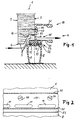
- Figure 1 shows an embodiment of a door leaf or a lower door leaf member of a door leaf 1 in a solid design, ie it consists not only of a sheet metal, but of a laminate or here made of wood, which is a clear distance between the outside 2 and the inside 3 fills out.
- the end wall 5 facing the bottom of the door opening to be closed in the closed state of the door leaf is tapered as seen from the outside, lower, approximately horizontally running end edge 6, here in the form of an oblique step such that seen from the outside 2 to the inside 3 a tapering space 16 formed upward by this taper is formed.
- a reinforcement strip designated overall by 17, is attached, which ensures that the lower end area 4 does not sag when the door leaf is open, ie when the door leaf 1 lies approximately horizontally under the ceiling.
- the reinforcement bar 17 has an approximately U-shaped profile, the web 22 located between the two legs 21 in its upper section, which bears against the inside 3 of the door leaf 1, has a series of bores 19 arranged one behind the other in the longitudinal direction of the end wall 5, through which bolts 20 are performed, with which the reinforcing bar 17 is screwed to the wooden door leaf 1.
- the web 22 of this U-profile protrudes beyond the lower edge of the inside 3 formed by the tapering region 16 and overlaps the tapering region 16.
- the ventilation openings 11 are provided in the web, namely as simple openings without special edge formation.
- a fixing formation 23 is then provided on the reinforcing strip 17, which has two holding strips 25 directed towards each other below a cavity 24, which are encompassed by a fixing profile 15 of a seal 8, which in a manner similar to that after Embodiment according to Figures 1 and 2 formed and described is fixed to the reinforcing bar.
- Fig. 2 shows that the ventilation openings are formed in the simplest way in the bottom of the reinforcing bar 17 as openings.
- An arrow in FIG. 1 shows the passage of air through the openings 11.
Abstract
Description
Die Erfindung bezieht sich auf ein Torblatt mit den Merkmalen des Oberbegriffes des Anspruches 1.The invention relates to a door leaf with the features of the preamble of claim 1.
Tore der hier in Rede stehenden Arten mit Belüftungsöffnungen für den Luftaustausch, vor allem in solchen Räumen, die sonst keine Belüftung aufweisen, wie insbesondere Garagen, werden heute bevorzugt mit in vertikaler Richtung über Kopf bewegbaren ein- oder mehrteiligen Torblattausführungen ausgerüstet. Bei solchen Torblättern ist an der Unterkante häufig eine elastische Dichtung angeordnet, die bei Verfahren des Torblattes in die Schließlage am Boden der Toröffnung angreift und verhindert, daß bei entsprechendem Windeinfall Schmutz in die Garage gelangt. Außerdem kann eine solche Leiste dazu dienen, einen unkontrolliert großen Luftspalt zwischen der unteren Stirnseite des Torblattes und dem Boden zu verhindern. Solche Torblätter sind - insbesondere in aufwendigerer Ausführung - mehrschichtig aufgebaut, beispielsweise außen und innen aus Blech mit ausgeschäumtem Innenraum oder aber auch aus Holz oder holzähnlichen Werkstoffen gefertigt, letztere auch in Form von Rahmenkonstruktionen, zwischen denen dünnwandige, geschlossene oder verglaste Felder angeordnet sind.Gates of the types in question here with ventilation openings for air exchange, especially in rooms which otherwise have no ventilation, such as garages in particular, are nowadays preferably equipped with single or multi-part door leaf designs which can be moved vertically overhead. In such door leaves, an elastic seal is often arranged on the lower edge, which engages when the door leaf is moved into the closed position at the bottom of the door opening and prevents dirt from entering the garage in the event of a corresponding wind. In addition, such a strip can serve to prevent an uncontrolled large air gap between the lower end face of the door leaf and the floor. Such door leaves are - in particular in a more elaborate design - built up in multiple layers, for example, outside and inside of sheet metal with a foamed interior or made of wood or wood-like materials, the latter also in the form of frame structures, between which thin-walled, closed or glazed fields are arranged.
Dabei ist es bereits bekannt - CH-PS 429103 -, im in der Schließstellung unteren Randbereich des Torblattes Öffnungen für den Luftdurchtritt vorzusehen. Dabei handelt es sich um eine Abschlußleiste, die insoweit dichtend an eine Bodenschwelle der zu verschlißenden Torblattöffnung anschlägt. Die Anordnung von Durchlüftungsöffnungen im unteren Randbereich des Torblattes hat den Vorteil, daß man dort in der Gestaltung der Lüftungsöffnungen selbst weniger eingeschränkt ist, als dies bei Belüftungsöffnungen - beispielsweise in Schlitzform - in der Torblattfläche der Fall ist. Andererseits ist die Schwellenausbildung im Durchfahrtsbereich der Toröffnung störend, und durch die Öffnungsmündung zum Boden hin wird eine umgelenkte Strömungsführung für die durchtretende Luft erforderlich.It is already known - CH-PS 429103 - to provide openings for the passage of air in the lower edge region of the door leaf in the closed position. This is an end strip that so far strikes a threshold against the threshold of the door leaf opening to be worn. The arrangement of ventilation openings in the lower edge region of the door leaf has the advantage that there is less restriction there in the design of the ventilation openings than is the case with ventilation openings - for example in the form of a slot - in the door leaf surface. On the other hand, the threshold formation in the passage area of the door opening is disruptive, and a deflected flow guidance for the air passing through the opening mouth towards the floor is required.
Der Erfindung liegt die Aufgabe zugrunde, ein Torblatt der in Rede stehenden Art zur Verfügung zu stellen, das auch ohne eine Schwellenausbildung im Garagenbodenbereich einen guten Abschluß im Schließzustand erzielt und bei dem die Strömungsrichtung der die Lüftungsöffnungen durchtretenden Luft weitgehend von Hindernissen frei ist.The invention has for its object to provide a door leaf of the type in question, which achieves a good conclusion in the closed state even without a threshold formation in the garage floor area and in which the flow direction of the air passing through the ventilation openings is largely free of obstacles.
Ausgehend von einem Torblatt mit den Merkmalen des Oberbegriffes des Anspruches 1 wird diese Aufgabe erfindungsgemäß durch dessen kennzeichnende Merkmale gelöst.Starting from a door leaf with the features of the preamble of claim 1, this object is achieved according to the invention by its characterizing features.
Erfindungsgemäß wird bei einem mehrschichtigen oder massiv ausgebildetem Torblatt derart vorgegangen, daß die untere, dem Boden in der Schließstellung des Torblattes zugewandte Abschlußwandung zur Innenseite hin gesehen nach oben hin verjüngt ausgebildet ist, insbesondere in gestufter Ausgestaltung, und daß eine im unteren Abschlußbereich an der Innenseite des Torblattes vorgesehene Leiste diese Innenseite nach unten überragend in den verjüngten Bereich hinein vorspringt und dort die Belüftungsöffnungen aufweist. Auch in diesem Falle lassen sich die Belüftungsöffnungen ohne irgendwelche Rücksichten auf Regeneinfall und dergleichen als einfache Durchbrechungen, beispielsweise durch Stanzen, herstellen. Eine Dichtung ist im Bereich unterhalb der Belüftungsöffnungen angeordnet, derart, daß der Raum unterhalb der außenseitigen unteren Abschlußkante des Torblattes über den durch die Verjüngung geschaffenen Raum in die Belüftungsöffnungen mündet, ohne von der entsprechend weit von der Außenseite des Torblattes entfernt angeordneten Dichtung behindert zu werden.According to the invention, a multilayer or solid door leaf is designed such that the lower end wall facing the floor in the closed position of the door leaf is tapered towards the inside, particularly in a stepped configuration, and that one is in the lower end region on the inside of the door leaf provided this inner side protrudes downwards into the tapered area and there has the ventilation openings. In this case, too, the ventilation openings can be produced as simple openings, for example by punching, without any consideration of rain and the like. A seal is arranged in the area below the ventilation openings in such a way that the space below the outside lower end edge of the door leaf opens into the ventilation openings via the space created by the tapering, without being impeded by the seal arranged correspondingly far from the outside of the door leaf .
Bei der erfindungsgemäßen Ausbildung wird davon ausgegangen, daß die untere, außenseitige Abschlußkante des Torblattes einen gewissen Abstand von dem Boden der Toröffnung in der vollständigen Schließlage des Torblattes einhält, was bereits aus praktischen Gründen grundsätzlich der Fall ist.In the embodiment according to the invention, it is assumed that the lower, outer end edge of the door leaf maintains a certain distance from the bottom of the door opening in the fully closed position of the door leaf, which is basically the case for practical reasons.
Die Belüftungsöffnungen erstrecken sich vorzugsweise über den gesamten Längsbereich der unteren Abschlußwandung des Tores bzw. des Torgliedes hinweg.The ventilation openings preferably extend over the entire longitudinal region of the lower end wall of the door or of the door member.
Weitere bevorzugte Ausführungsformen der Erfindung ergeben sich aus den Unteransprüchen im Zusammenhang mit den in der Zeichnung wiedergegebenen Ausführungsbeispielen, auf die besonders Bezug genommen wird und deren nachfolgende Beschreibung die Erfindung näher erläutert.Further preferred embodiments of the invention result from the subclaims in connection with the exemplary embodiments shown in the drawing, to which particular reference is made and the following description of which explains the invention in more detail.
Es zeigen:
- Figur 1 einen Vertikalschnitt durch den im Schließzustand unteren Bereich eines Torblattes bzw. Torblattgliedes, das massiv, insbesondere aus Holz, ausgebildet ist;
Figur 2 einen Schnitt nach Figur 1.
- Figure 1 shows a vertical section through the lower region of a door leaf or door leaf member in the closed state, which is solid, in particular made of wood;
- FIG. 2 shows a section according to FIG. 1.
Figur 1 zeigt ein Ausführungsbeispiel eines Torblattes bzw. eines unteren Torblattgliedes eines Torblattes 1 in massiver Ausführung, d.h. es besteht nicht nur aus einem Blech, sondern aus einem Schichtkörper bzw. hier aus Holz, das zwischen der Außenseite 2 und der Innenseite 3 einen deutlichen Abstand ausfüllt. Die dem Boden der zu verschließenden Toröffnung im Schließzustand des Torblattes zugewandte Abschlußwandung 5 ist von der außenseitigen, unteren, etwa horizontal verlaufenden Abschlußkante 6 aus gesehen verjüngt ausgebildet, hier in Form einer schräg verlaufenden Stufung derart, daß von der Außenseite 2 zur Innenseite 3 hin gesehen ein durch diese Verjüngung nach oben hin gebildeter Verjüngungsraum 16 gebildet wird. An dem derart nach oben hin versetzten unteren Endabschnitt der Innenwandung 3 ist eine insgesamt mit 17 bezeichnete Verstärkungsleiste angebracht, die dafür sorgt, daß der untere Abschlußbereich 4 bei geöffnetem Torblatt, d. h. bei etwa horizontal unter der Decke liegendem Torblatt 1 dieses nicht nach unten durchhängt. Die Verstärkungsleiste 17 weist ein etwa U-förmiges Profil auf, dessen zwischen den beiden Schenkeln 21 gelegener Steg 22 in seinem oberen, an der Innenseite 3 des Torblattes 1 anliegenden Abschnitt eine Reihe von in Längsrichtung der Abschlußwandung 5 hintereinander angeordneten Bohrungen 19 aufweist, durch welche Schraubbolzen 20 geführt sind, mit denen die Verstärkungsleiste 17 an dem Holztorblatt 1 festgeschraubt ist. Der Steg 22 dieses U-Profils ragt über die durch den Verjüngungsbereich 16 gebildete Unterkante der Innenseite 3 hinaus und übergreift den Verjüngungsbereich 16. In diesem Übergreifungsbereich 18 sind die Belüftungsöffnungen 11 in dem Steg vorgesehen, und zwar als einfache Durchbrechungen ohne besondere Randausbildung.Figure 1 shows an embodiment of a door leaf or a lower door leaf member of a door leaf 1 in a solid design, ie it consists not only of a sheet metal, but of a laminate or here made of wood, which is a clear distance between the
Nach unten hin an den unteren Schenkel 21 anschließend ist an der Verstärkungsleiste 17 eine Festlegeausbildung 23 vorgesehen, die unterhalb eines Hohlraumes 24 zwei aufeinander zu gerichtete Halteleisten 25 aufweist, die von einem Festlegeprofil 15 einer Dichtung 8 umgriffen werden, die in ähnlicher Weise wie nach dem Ausführungsbeispiel nach den Figuren 1 und 2 geschildert ausgebildet und an der Verstärkungsleiste festgelegt ist.Downward to the
Fig. 2 zeigt, daß die Beluftungsöffnungen auf einfachste Art im Boden der Verstärkungsleiste 17 als Durchbrechungen ausgebildet sind. Ein Pfeil in Fig. 1 zeigt den Luftübertritt durch die Öffnungen 11.Fig. 2 shows that the ventilation openings are formed in the simplest way in the bottom of the
Claims (4)
- A single or multi-section up-and-over door leaf which is provided with ventilation ports for the passage of air between the space in front of the door and the space behind the door, the ventilation ports being arranged in the substantially horizontally extending closure region of the door leaf which is at the bottom in the closed position, and being substantially concealed by the external lower closure edge thereof, the door leaf being constructed, between its exterior (2) and interior (3), as a laminated body or with the interior and exterior surfaces (2,3) clearly spaced having at least a solid frame, more particularly made of wood, and the lower closure edge (5) facing the bottom of the door opening sloping upwardly (16), in the direction from the exterior (2) of the door to the interior (3) thereof, and more particularly, being stepped, characterised in that a separate reinforcing strip (17), which extends in the longitudinal direction of the closure end face wall (5), is provided on the interior (3) of the door (1), this reinforcing strip (17) at least partially overlapping the sloping portion (16) when viewed towards the bottom, the ventilation ports (11) being provided in this area of overlap (18), and that on the side of the reinforcing strip (17) facing the bottom of the door opening, there is provided a support structure (23) for a seal (8) which extends along the lower closure end face wall (5), and that this seal (8) particularly is in the form of a hollow bead, flange or the like, which preferably has two retaining strips (25) projecting towards each other underneath a hollow space (24).
- A door leaf according to claim 1, characterised in that the reinforcing strip (17), which is more particularly produced as an extruded section, has in its upper region adjacent to the interior surface (3) of the door leaf (1), a series of bore holes (19) for the insertion of bolts (20) for securing it to the door leaf (1), and, in the underlying area of overlap (18) which overhangs the interior surface (3) in the region of the sloping portion (16), is provided with ventilation ports (11) formed as openings.
- A door leaf according to claim 1 or 2, charaterised in that the reinforcing strip (17) has a U-shaped profile in which the web (22) which connects the legs (21) of the U is arranged facing the interior surface (3) of the door leaf and contains in its upper longitudinally extending portion the bore holes (19) and in the underlying region of overlap (18) the ventilation ports (11).
- A door leaf according to any one of the claims 1 to 3, characterised in that the ventilation ports (11) are constructed as elongate openings extending in the longitudinal direction of the lower substantially horizontally running closure wall (5), said openings extending one after another in a row in this direction over at least part of the overall length of the lower closure wall (5).
Priority Applications (1)
| Application Number | Priority Date | Filing Date | Title |
|---|---|---|---|
| AT87100951T ATE58413T1 (en) | 1986-01-27 | 1987-01-23 | DOOR LEAF WITH VENTILATION OPENINGS. |
Applications Claiming Priority (2)
| Application Number | Priority Date | Filing Date | Title |
|---|---|---|---|
| DE8601985U DE8601985U1 (en) | 1986-01-27 | 1986-01-27 | |
| DE8601985U | 1986-01-27 |
Publications (4)
| Publication Number | Publication Date |
|---|---|
| EP0230998A2 EP0230998A2 (en) | 1987-08-05 |
| EP0230998A3 EP0230998A3 (en) | 1987-12-23 |
| EP0230998B1 EP0230998B1 (en) | 1990-11-14 |
| EP0230998B2 true EP0230998B2 (en) | 1995-10-18 |
Family
ID=6790964
Family Applications (1)
| Application Number | Title | Priority Date | Filing Date |
|---|---|---|---|
| EP87100951A Expired - Lifetime EP0230998B2 (en) | 1986-01-27 | 1987-01-23 | Door leaf with ventilation openings |
Country Status (7)
| Country | Link |
|---|---|
| EP (1) | EP0230998B2 (en) |
| AT (1) | ATE58413T1 (en) |
| DE (2) | DE8601985U1 (en) |
| DK (1) | DK166739B1 (en) |
| ES (1) | ES2018789T5 (en) |
| GR (1) | GR3002554T3 (en) |
| NO (1) | NO165454C (en) |
Families Citing this family (5)
| Publication number | Priority date | Publication date | Assignee | Title |
|---|---|---|---|---|
| DE4101013A1 (en) * | 1991-01-15 | 1992-07-16 | Hoermann Kg | DOOR LEAF WITH VENTILATION OPENINGS |
| CH691188A5 (en) * | 1995-11-20 | 2001-05-15 | Hesco Schweiz Ag | Door with ventilation device. |
| EP1498569B1 (en) * | 2003-07-17 | 2014-06-04 | Planet GDZ AG | Door seal |
| US8850747B2 (en) | 2006-10-13 | 2014-10-07 | Liexco, S.A. | Door with closing profile and integrated ventilation |
| EP2118424B1 (en) * | 2006-10-13 | 2017-05-24 | Rubelko | Door with closing profile and integrated ventilation |
Family Cites Families (1)
| Publication number | Priority date | Publication date | Assignee | Title |
|---|---|---|---|---|
| DE1905233U (en) * | 1964-08-05 | 1964-11-26 | Hofeto Maschinen Und Stahlbau | GARAGE DOOR. |
-
1986
- 1986-01-27 DE DE8601985U patent/DE8601985U1/de not_active Expired
-
1987
- 1987-01-23 ES ES87100951T patent/ES2018789T5/en not_active Expired - Lifetime
- 1987-01-23 AT AT87100951T patent/ATE58413T1/en not_active IP Right Cessation
- 1987-01-23 DE DE8787100951T patent/DE3766115D1/en not_active Expired - Fee Related
- 1987-01-23 EP EP87100951A patent/EP0230998B2/en not_active Expired - Lifetime
- 1987-01-26 DK DK040187A patent/DK166739B1/en not_active IP Right Cessation
- 1987-01-27 NO NO870316A patent/NO165454C/en unknown
-
1991
- 1991-01-30 GR GR90401118T patent/GR3002554T3/en unknown
Also Published As
| Publication number | Publication date |
|---|---|
| ATE58413T1 (en) | 1990-11-15 |
| GR3002554T3 (en) | 1993-01-25 |
| NO870316L (en) | 1987-07-28 |
| DK40187A (en) | 1987-07-28 |
| NO165454B (en) | 1990-11-05 |
| EP0230998B1 (en) | 1990-11-14 |
| DK40187D0 (en) | 1987-01-26 |
| EP0230998A2 (en) | 1987-08-05 |
| DE8601985U1 (en) | 1987-05-27 |
| ES2018789B3 (en) | 1991-05-16 |
| EP0230998A3 (en) | 1987-12-23 |
| NO165454C (en) | 1991-02-13 |
| NO870316D0 (en) | 1987-01-27 |
| DE3766115D1 (en) | 1990-12-20 |
| ES2018789T5 (en) | 1997-07-01 |
| DK166739B1 (en) | 1993-07-05 |
Similar Documents
| Publication | Publication Date | Title |
|---|---|---|
| DE2101657A1 (en) | Prefabricated assembly of door frame and door for installation at the construction site | |
| EP0164755A2 (en) | Sound insulating window | |
| EP0230998B2 (en) | Door leaf with ventilation openings | |
| EP0103766B1 (en) | Roller shutter box or venetian blind box for windows or doors | |
| DE19718714C2 (en) | Insulating element made of two or more panes made of glass or plastic | |
| EP0497134B1 (en) | Gate leaf with aerating openings | |
| DE19505222C2 (en) | Wing arrangement, consisting essentially of a stick frame and two swing frames provided on this stick frame | |
| DE4305283C1 (en) | Window roller-shutter housing forming frame cross-member - gas mating chamfers on cross-member and top member of hinging window | |
| EP0114412B1 (en) | Fixed window or poor frame with superposable box for roller shutter or the like | |
| AT408566B (en) | WINDOWS, ESPECIALLY ROOF WINDOWS | |
| DE2518551A1 (en) | VENTILATION DEVICE | |
| DE19631232C2 (en) | Shower cubicle with shower plateau | |
| DE10361123B4 (en) | Lost formwork for holding a shutter or a blind | |
| EP4060157B1 (en) | Gate comprising a pass door | |
| DE10011576B4 (en) | Window or door frames for containers or the like | |
| CH644667A5 (en) | Casing with window and/or door arranged in brickwork | |
| WO1999009357A1 (en) | Ventilator for window elements | |
| DE3006987A1 (en) | Window casing assembly - uses prefab. concrete panels with protruding guide ribs for seating window frame | |
| DE4315644C2 (en) | Building window | |
| EP4299870A1 (en) | Frame for a door with an extrusion frame and threshold, door with such a frame and method of manufacturing this door | |
| EP0736436B1 (en) | Railway vehicle | |
| EP0108880A2 (en) | Window | |
| DE20220923U1 (en) | Building door or window frame has leaf frame and blind frame with cylindrical recess to receive ventilation blower | |
| DE891732C (en) | Double glazed window or double glazed door | |
| DE10235648A1 (en) | Window or window door made of wood, or more particularly plastic, has an undercut window or door frame and a window or door frame stop angled inwards towards the window sash |
Legal Events
| Date | Code | Title | Description |
|---|---|---|---|
| PUAI | Public reference made under article 153(3) epc to a published international application that has entered the european phase |
Free format text: ORIGINAL CODE: 0009012 |
|
| AK | Designated contracting states |
Kind code of ref document: A2 Designated state(s): AT BE CH DE ES FR GB GR IT LI LU NL SE |
|
| PUAL | Search report despatched |
Free format text: ORIGINAL CODE: 0009013 |
|
| AK | Designated contracting states |
Kind code of ref document: A3 Designated state(s): AT BE CH DE ES FR GB GR IT LI LU NL SE |
|
| 17P | Request for examination filed |
Effective date: 19880620 |
|
| 17Q | First examination report despatched |
Effective date: 19890621 |
|
| GRAA | (expected) grant |
Free format text: ORIGINAL CODE: 0009210 |
|
| AK | Designated contracting states |
Kind code of ref document: B1 Designated state(s): AT BE CH DE ES FR GB GR IT LI LU NL SE |
|
| REF | Corresponds to: |
Ref document number: 58413 Country of ref document: AT Date of ref document: 19901115 Kind code of ref document: T |
|
| ET | Fr: translation filed | ||
| REF | Corresponds to: |
Ref document number: 3766115 Country of ref document: DE Date of ref document: 19901220 |
|
| ITF | It: translation for a ep patent filed |
Owner name: BUGNION S.P.A. |
|
| GBT | Gb: translation of ep patent filed (gb section 77(6)(a)/1977) | ||
| PLBI | Opposition filed |
Free format text: ORIGINAL CODE: 0009260 |
|
| 26 | Opposition filed |
Opponent name: HOESCH AG, Effective date: 19910814 |
|
| NLR1 | Nl: opposition has been filed with the epo |
Opponent name: HOESCH AG. |
|
| ITTA | It: last paid annual fee | ||
| REG | Reference to a national code |
Ref country code: GR Ref legal event code: FG4A Free format text: 3002554 |
|
| PLAB | Opposition data, opponent's data or that of the opponent's representative modified |
Free format text: ORIGINAL CODE: 0009299OPPO |
|
| R26 | Opposition filed (corrected) |
Opponent name: HOESCH AG, Effective date: 19910814 |
|
| EPTA | Lu: last paid annual fee | ||
| EAL | Se: european patent in force in sweden |
Ref document number: 87100951.0 |
|
| PUAH | Patent maintained in amended form |
Free format text: ORIGINAL CODE: 0009272 |
|
| STAA | Information on the status of an ep patent application or granted ep patent |
Free format text: STATUS: PATENT MAINTAINED AS AMENDED |
|
| 27A | Patent maintained in amended form |
Effective date: 19951018 |
|
| AK | Designated contracting states |
Kind code of ref document: B2 Designated state(s): AT BE CH DE ES FR GB GR IT LI LU NL SE |
|
| PGFP | Annual fee paid to national office [announced via postgrant information from national office to epo] |
Ref country code: BE Payment date: 19951109 Year of fee payment: 10 |
|
| ITF | It: translation for a ep patent filed |
Owner name: BUGNION S.P.A. |
|
| REG | Reference to a national code |
Ref country code: CH Ref legal event code: AEN Free format text: AUFRECHTERHALTUNG DES PATENTES IN GEAENDERTER FORM |
|
| NLR2 | Nl: decision of opposition | ||
| ET3 | Fr: translation filed ** decision concerning opposition | ||
| GBTA | Gb: translation of amended ep patent filed (gb section 77(6)(b)/1977) |
Effective date: 19960124 |
|
| NLR3 | Nl: receipt of modified translations in the netherlands language after an opposition procedure | ||
| REG | Reference to a national code |
Ref country code: ES Ref legal event code: DC2A Kind code of ref document: T5 Effective date: 19960316 |
|
| K2C3 | Correction of patent specification (complete document) published |
Effective date: 19901114 |
|
| APAC | Appeal dossier modified |
Free format text: ORIGINAL CODE: EPIDOS NOAPO |
|
| APAC | Appeal dossier modified |
Free format text: ORIGINAL CODE: EPIDOS NOAPO |
|
| PG25 | Lapsed in a contracting state [announced via postgrant information from national office to epo] |
Ref country code: BE Free format text: LAPSE BECAUSE OF NON-PAYMENT OF DUE FEES Effective date: 19970131 |
|
| REG | Reference to a national code |
Ref country code: ES Ref legal event code: DC2A Kind code of ref document: T5 Effective date: 19970130 |
|
| NLR4 | Nl: receipt of corrected translation in the netherlands language at the initiative of the proprietor of the patent | ||
| ET2 | Fr: translation filed ** revision of the translation of the modified patent after opposition | ||
| ET3 | Fr: translation filed ** decision concerning opposition | ||
| PGFP | Annual fee paid to national office [announced via postgrant information from national office to epo] |
Ref country code: GR Payment date: 19980129 Year of fee payment: 12 |
|
| PG25 | Lapsed in a contracting state [announced via postgrant information from national office to epo] |
Ref country code: GR Free format text: LAPSE BECAUSE OF NON-PAYMENT OF DUE FEES Effective date: 19990131 |
|
| REG | Reference to a national code |
Ref country code: GB Ref legal event code: IF02 |
|
| PGFP | Annual fee paid to national office [announced via postgrant information from national office to epo] |
Ref country code: CH Payment date: 20041229 Year of fee payment: 19 |
|
| PGFP | Annual fee paid to national office [announced via postgrant information from national office to epo] |
Ref country code: FR Payment date: 20041230 Year of fee payment: 19 Ref country code: AT Payment date: 20041230 Year of fee payment: 19 |
|
| PGFP | Annual fee paid to national office [announced via postgrant information from national office to epo] |
Ref country code: GB Payment date: 20050113 Year of fee payment: 19 |
|
| PGFP | Annual fee paid to national office [announced via postgrant information from national office to epo] |
Ref country code: SE Payment date: 20050114 Year of fee payment: 19 |
|
| PGFP | Annual fee paid to national office [announced via postgrant information from national office to epo] |
Ref country code: LU Payment date: 20050124 Year of fee payment: 19 |
|
| PGFP | Annual fee paid to national office [announced via postgrant information from national office to epo] |
Ref country code: ES Payment date: 20050125 Year of fee payment: 19 |
|
| PGFP | Annual fee paid to national office [announced via postgrant information from national office to epo] |
Ref country code: NL Payment date: 20050128 Year of fee payment: 19 |
|
| PGFP | Annual fee paid to national office [announced via postgrant information from national office to epo] |
Ref country code: DE Payment date: 20050222 Year of fee payment: 19 |
|
| APAH | Appeal reference modified |
Free format text: ORIGINAL CODE: EPIDOSCREFNO |
|
| PG25 | Lapsed in a contracting state [announced via postgrant information from national office to epo] |
Ref country code: GB Free format text: LAPSE BECAUSE OF NON-PAYMENT OF DUE FEES Effective date: 20060123 Ref country code: AT Free format text: LAPSE BECAUSE OF NON-PAYMENT OF DUE FEES Effective date: 20060123 |
|
| PG25 | Lapsed in a contracting state [announced via postgrant information from national office to epo] |
Ref country code: SE Free format text: LAPSE BECAUSE OF NON-PAYMENT OF DUE FEES Effective date: 20060124 Ref country code: ES Free format text: LAPSE BECAUSE OF NON-PAYMENT OF DUE FEES Effective date: 20060124 |
|
| PG25 | Lapsed in a contracting state [announced via postgrant information from national office to epo] |
Ref country code: LU Free format text: LAPSE BECAUSE OF NON-PAYMENT OF DUE FEES Effective date: 20060131 Ref country code: LI Free format text: LAPSE BECAUSE OF NON-PAYMENT OF DUE FEES Effective date: 20060131 Ref country code: FR Free format text: LAPSE BECAUSE OF NON-PAYMENT OF DUE FEES Effective date: 20060131 Ref country code: CH Free format text: LAPSE BECAUSE OF NON-PAYMENT OF DUE FEES Effective date: 20060131 |
|
| PGFP | Annual fee paid to national office [announced via postgrant information from national office to epo] |
Ref country code: IT Payment date: 20060131 Year of fee payment: 20 |
|
| PG25 | Lapsed in a contracting state [announced via postgrant information from national office to epo] |
Ref country code: NL Free format text: LAPSE BECAUSE OF NON-PAYMENT OF DUE FEES Effective date: 20060801 Ref country code: DE Free format text: LAPSE BECAUSE OF NON-PAYMENT OF DUE FEES Effective date: 20060801 |
|
| REG | Reference to a national code |
Ref country code: CH Ref legal event code: PL |
|
| EUG | Se: european patent has lapsed | ||
| GBPC | Gb: european patent ceased through non-payment of renewal fee |
Effective date: 20060123 |
|
| NLV4 | Nl: lapsed or anulled due to non-payment of the annual fee |
Effective date: 20060801 |
|
| REG | Reference to a national code |
Ref country code: FR Ref legal event code: ST Effective date: 20060929 |
|
| REG | Reference to a national code |
Ref country code: ES Ref legal event code: FD2A Effective date: 20060124 |