EP0230367B1 - Apparatus for judging inner pressure of filled can - Google Patents
Apparatus for judging inner pressure of filled can Download PDFInfo
- Publication number
- EP0230367B1 EP0230367B1 EP87300257A EP87300257A EP0230367B1 EP 0230367 B1 EP0230367 B1 EP 0230367B1 EP 87300257 A EP87300257 A EP 87300257A EP 87300257 A EP87300257 A EP 87300257A EP 0230367 B1 EP0230367 B1 EP 0230367B1
- Authority
- EP
- European Patent Office
- Prior art keywords
- roll
- filled
- measuring
- barrel
- inner pressure
- Prior art date
- Legal status (The legal status is an assumption and is not a legal conclusion. Google has not performed a legal analysis and makes no representation as to the accuracy of the status listed.)
- Expired
Links
Images

Classifications
-
- G—PHYSICS
- G01—MEASURING; TESTING
- G01L—MEASURING FORCE, STRESS, TORQUE, WORK, MECHANICAL POWER, MECHANICAL EFFICIENCY, OR FLUID PRESSURE
- G01L11/00—Measuring steady or quasi-steady pressure of a fluid or a fluent solid material by means not provided for in group G01L7/00 or G01L9/00
-
- G—PHYSICS
- G01—MEASURING; TESTING
- G01M—TESTING STATIC OR DYNAMIC BALANCE OF MACHINES OR STRUCTURES; TESTING OF STRUCTURES OR APPARATUS, NOT OTHERWISE PROVIDED FOR
- G01M3/00—Investigating fluid-tightness of structures
- G01M3/02—Investigating fluid-tightness of structures by using fluid or vacuum
- G01M3/36—Investigating fluid-tightness of structures by using fluid or vacuum by detecting change in dimensions of the structure being tested
Definitions
- This invention relates to a device for measuring the inner or internal pressure in filled cans and, more particularly, to an apparatus for checking whether the filled can inner pressure is satisfactory by measuring the reaction force provided by the filled can when the can barrel is pressed in the direction of the diameter thereof.
- a prior art apparatus for determining the filled can inner pressure by measuring the reaction force provided by the can barrel (can body) comprises a back-up unit and a measuring unit.
- the distance between a back-up roll of the back-up unit and a measuring roll of the measuring unit is set to a value which is very slightly smaller than the average value of the barrel of filled cans to be measured.
- the amount of displacement of the measuring roll engaging with a predetermined press strength to the barrel of a filled can when the can barrel passes through this gap is measured by a load cell to judge whether the inner pressure is satisfactory.
- the sectional profile of the can barrel is not really circular, but there is an error of about 0.7 mm at the most between the maximum and minimum diameters.
- the disclosed apparatus comprises, as shown in Fig. 5, a back-up unitA, having a cylindrical and rotatable back-up roll 1; and a measuring unit B having a measuring roll 3 having a crown-like outer periphery 2 and rotatably supported by a support rod 4 which is mounted in a bearing 5 such that the measuring roll 3 can be advanced and retreated with respect to the back-up roll 1, and a load cell 6 being operated by the moving of the roll 3 or the rod 4; and a conveyor unit having rope belts 7a to 7d, the belts 7a and 7b being adapted to be in contact with both sides of an upper portion of the barrel of a filled can C1, and the belts 7c and 7d in contact with a lower portion of the can barrel, to guide the can C such that the can barrel C1 proceeds through the gap between the rolls 1 and 3.
- Reference numeral 8 is a filled can support member for supporting the
- the can body is guided in a state sandwiched between the four rope belts to proceed without rotation, and two sets of a back-up unit and a measuring unit are provided to hold said can between them.
- Each measuring roll thrusts the same portion of the body of a proceeding filled can with a different amount of thrust to the other.
- each reaction force of the can barrel is measured by each load cell. Finally, whether the internal pressure is satisfactory is judged by comparing the difference between the two measured values with the standard value.
- the apparatus for judging the filled can inner pressure disclosed in the publication noted above has two sets of back-up and measuring units for low inner pressure filled cans and a unit for measuring the extent of deformation of the end or lid of high inner pressure filled cans. Therefore, the apparatus is complicated and expensive. Further, the measurement is done twice with respect to the same portion of the body of the filled can, and the two measurement values are processed. Further, separate methods of measurements have to be used for low inner pressure filled cans and high inner pressure filled cans. Thus the treatment becomes complicated.
- This invention according to claim 1 has been made in order to solve the above problems.
- Fig. 1 is a schematic front view showing an apparatus for judging the inner pressure of a filled can according to the invention
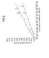
- Fig. 2 is a graph showing the relation between the can barrel reaction force and can inner pressure when the distance between two rolls is set to be smaller by 1 mm than the average can barrel diameter and the radius of arcular sectional profile of roll is 50 and 136 mm
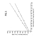
- Fig. 3 is a graph showing the relation between the can barrel reaction force and can inner pressure when the distance between the rolls is smaller by 2 m than the average can barrel diameter and the radius of the arcular sectional profile of roll is 50 and 136 mm
- Fig. 1 is a schematic front view showing an apparatus for judging the inner pressure of a filled can according to the invention
- Fig. 2 is a graph showing the relation between the can barrel reaction force and can inner pressure when the distance between two rolls is set to be smaller by 1 mm than the average can barrel diameter and the radius of arcular sectional profile of roll is 50 and 136 mm
- Fig. 3 is a graph showing the
- Fig. 5 is a schematic front view showing a prior art filled can inner pressure judgement apparatus.
- the distance between the back-up and measuring rolls is smaller by 2 mm or more than the average diameter of the central portion of the can barrel.
- the ratio of the reaction force of the can barrel and can inner pressure becomes constant when the can barrel passes through the gap between the two rolls. It is thus possible to judge whether the filled can is satisfactory with the desired can inner pressure as the limit pressure.
- Fig. 2 shows the relation between the reaction force of the can barrel and can inner pressure when the distance between two rolls is set to be smaller by 1 mm than average can barrel diameter and a filled can with a diameter of approximately 66 mm and the height of 122 mm is passed between the two rollers.
- Shown at P i.e., circles 0
- Shown at Q i.e., crosses x) are values when a roll with an arcuate profile of 136 mm is used. Many of these values are deviated from the dashed plot X and dot-and- bar plot Y.
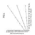
- Fig. 4 shows the relation between the can barrel reaction force and can inner pressure when a roll with a crown-like outer periphery having an arcuate sectional profile with a radius of 136 mm with the distance between the rolls set to be smaller by 1 mm (cross marks * ), smaller by 2 mm (circular marks 0) and smaller by 3 mm (crosses x).
- cross marks * the distance between the rolls is smaller by 1 mm as shown by cross marks ( * )
- the difference in the can barrel reaction force is small compared with the difference in the can inner pressure.
- the can body is pressed by a roll having a crown-like outer periphery with an arcuate section profile with a radius of 60 mm or more on a plane containing the roll axis.
- Table 1 Roll shape, extent of thrusting and damage state.
- the table shows the result of damage to the can barrel when the inner pressure of a filled can with a diameter of about 66 mm and a height of about 122 mm is measured using rolls having a length of 40 mm and having crown-like sectional profiles having arcuate sectional profiles with radii of 50,60 and 136 mm in a plane containing the roll axis.
- the can inner pressure in both cans the internal pressure of which is low and ones that of which is high, may be easily known by merely multiplying the can barrel reaction force by a proportionality constant. Further, since the proportionality constant is high, it is possible to obtain reliable judgement.
- FIG. 1 is a schematic v;ew showing an apparatus for judging filled can inner pressure according to the invention.
- parts A, B, C, 1,4,5,6 and 7 designate the same parts as shown by A, B, C, 1, 4, 5, and 7 shown in Fig. 5.
- Designated at 3A is a measuring roll consisting of a hard material, 2A the outer periphery of the measuring roll having an arcuate sectional profile and a radius of 60 mm or more, 9 a plate-like slide block, to which the back-up and measuring units A and B are connected integrally, 10 a base supporting the slide block 9 such that the block can be moved back and forth in a direction at right angles to the direction of progress of the can via springs 11, and 12a and 12b flat belts of conveyor adapted to be in forced contact with the opposite ends of the filled can in the axial direction thereof.
- the back-up roll 1 was also made of a hard material, and the position of the measuring roll 3A was determined such that the distance between the back-up and measuring rolls 1 and 3A is set to be smaller by 2 mm than the average diameter of the center of the barrel of filled cans.
- the measuring roll 3A was used one which had an arcuate i.e., crown-like outer periphery 2A with a radius of 136 mm and a length of 40 mm.
- Cans to be measured (with a diameter of about 66 mm and a height of approximately 122 mm) were almost successively supplied in between the upper and lower flat belts 12a and 12b.
- Each filled can was guided by the flat belts 12a and 12b to proceed toward the gap between the back-up and measuring rollers 1 and 3A. Almost all of the filled cans first came to be in contact with one of the rolls 1 and 3A. As a result, the back-up and measuring units A and B and slide block 9, these parts being integral with one another, are displaced against the spring forces of the spring 11. The filled can thus was fed through between and in contact with the rolls. The reaction force was measured and recorded by the load cell.
- the distance between the back-up and measuring rollers is set to be smaller by 2 mm or above than the average filled can barrel diameter. Therefore, it is possible to display the reaction force of the can barrel even if there are fluctuations of about 0.7 mm in the barrel diameter. And, since the displayed reaction force is linearly proportional to the filled can inner pressure, it is possible to judge the filled can inner pressure by merely passing the filled can between a back-up roll and a measuring roll. The judging process thus can be simply performed.
- the roll outer periphery has a crown-like sectional profile with a radius of 60 mm or above in a plane containing the roll axis, no damage is caused to the can barrel even if the distance between the two rolls is as above.
- the filled can inner pressure judgement apparatus comprises only a single set of back-up and measuring units, the construction is simple. Further, since the filled can is transferred by the upper and lower flat belts, the back-up and measuring rolls may be constructed to have sufficient lengths. It is thus possible to prevent damage to the can barrel. Further, since the back-up and measuring units and slide block are made integral and mounted to be movable in directions perpendicular to the direction of progress of the filled can via springs, even when the body of a filled can being fed by the flat belts strikes either the back-up or measuring roll first, the back-up and measuring units and slide block can move according to the movement of the can without causing damage to the can body, and the reaction force thereof can be measured accurately.
Landscapes
- Physics & Mathematics (AREA)
- General Physics & Mathematics (AREA)
- Measuring Fluid Pressure (AREA)
- Examining Or Testing Airtightness (AREA)
Description
- This invention relates to a device for measuring the inner or internal pressure in filled cans and, more particularly, to an apparatus for checking whether the filled can inner pressure is satisfactory by measuring the reaction force provided by the filled can when the can barrel is pressed in the direction of the diameter thereof.
- A prior art apparatus for determining the filled can inner pressure by measuring the reaction force provided by the can barrel (can body) comprises a back-up unit and a measuring unit. The distance between a back-up roll of the back-up unit and a measuring roll of the measuring unit is set to a value which is very slightly smaller than the average value of the barrel of filled cans to be measured. The amount of displacement of the measuring roll engaging with a predetermined press strength to the barrel of a filled can when the can barrel passes through this gap is measured by a load cell to judge whether the inner pressure is satisfactory. The sectional profile of the can barrel, however, is not really circular, but there is an error of about 0.7 mm at the most between the maximum and minimum diameters. Therefore, with the afore-mentioned distance between the back-up and measuring rolls, some cans may pass through the gap between the two rolls without almost being urged by these rollers. Thus, it is impossible to effect appropriate judgement as to whether the can inner pressure is satisfactory.
- An apparatus having an aim of solving the above problem is disclosed in Japanese Patent Laid-Open Publication No. 157537/84. The disclosed apparatus comprises, as shown in Fig. 5, a back-up unitA, having a cylindrical and rotatable back-up
roll 1; and a measuring unit B having ameasuring roll 3 having a crown-likeouter periphery 2 and rotatably supported by asupport rod 4 which is mounted in abearing 5 such that themeasuring roll 3 can be advanced and retreated with respect to the back-uproll 1, and aload cell 6 being operated by the moving of theroll 3 or therod 4; and a conveyor unit having rope belts 7a to 7d, thebelts 7a and 7b being adapted to be in contact with both sides of an upper portion of the barrel of a filled can C1, and thebelts rolls Reference numeral 8 is a filled can support member for supporting the bottom of proceeding filled cans. - In the apparatus disclosed in Fig. 5, the can body is guided in a state sandwiched between the four rope belts to proceed without rotation, and two sets of a back-up unit and a measuring unit are provided to hold said can between them. Each measuring roll thrusts the same portion of the body of a proceeding filled can with a different amount of thrust to the other. Then each reaction force of the can barrel is measured by each load cell. Finally, whether the internal pressure is satisfactory is judged by comparing the difference between the two measured values with the standard value.
- The apparatus for judging the filled can inner pressure disclosed in the publication noted above, however, has two sets of back-up and measuring units for low inner pressure filled cans and a unit for measuring the extent of deformation of the end or lid of high inner pressure filled cans. Therefore, the apparatus is complicated and expensive. Further, the measurement is done twice with respect to the same portion of the body of the filled can, and the two measurement values are processed. Further, separate methods of measurements have to be used for low inner pressure filled cans and high inner pressure filled cans. Thus the treatment becomes complicated.
- This invention according to
claim 1 has been made in order to solve the above problems. - Fig. 1 is a schematic front view showing an apparatus for judging the inner pressure of a filled can according to the invention; Fig. 2 is a graph showing the relation between the can barrel reaction force and can inner pressure when the distance between two rolls is set to be smaller by 1 mm than the average can barrel diameter and the radius of arcular sectional profile of roll is 50 and 136 mm; Fig. 3 is a graph showing the relation between the can barrel reaction force and can inner pressure when the distance between the rolls is smaller by 2 m than the average can barrel diameter and the radius of the arcular sectional profile of roll is 50 and 136 mm; Fig. 4 is a graph showing the relation between the can barrel reaction force and can inner pressure when a roll with an arcuate sectional profile of a radius of 136 mm is used and the distance between the rolls is set to be smaller by 1, 2 and 3 mm respectively than the average can barrel diameter; and Fig. 5 is a schematic front view showing a prior art filled can inner pressure judgement apparatus.
- In the method of judging the filled can inner pressure according to the invention, the distance between the back-up and measuring rolls is smaller by 2 mm or more than the average diameter of the central portion of the can barrel. Thus, the ratio of the reaction force of the can barrel and can inner pressure becomes constant when the can barrel passes through the gap between the two rolls. It is thus possible to judge whether the filled can is satisfactory with the desired can inner pressure as the limit pressure.
- The above can be known from the following derived from Figs. 2, 3 and 4.
- Fig. 2 shows the relation between the reaction force of the can barrel and can inner pressure when the distance between two rolls is set to be smaller by 1 mm than average can barrel diameter and a filled can with a diameter of approximately 66 mm and the height of 122 mm is passed between the two rollers. Shown at P (i.e., circles 0) are values when a roll with a crown-like outer periphery having an arcuate sectional profile with a radius of 50 mm is used. Shown at Q (i.e., crosses x) are values when a roll with an arcuate profile of 136 mm is used. Many of these values are deviated from the dashed plot X and dot-and- bar plot Y. This shows that, with the distance between the rollers noted above, the ratio between the can inner pressure and can barrel reaction force is not constant. But when the distance between the rollers is set to be smaller by 2 mm than the average can barrel diameter, as shown in Fig. 3, the ratio between the can inner pressure and can barrel reaction force is substantially constant in the case of the valued marked by the circles (0) and values marked by the crosses (x).
- Fig. 4 shows the relation between the can barrel reaction force and can inner pressure when a roll with a crown-like outer periphery having an arcuate sectional profile with a radius of 136 mm with the distance between the rolls set to be smaller by 1 mm (cross marks *), smaller by 2 mm (circular marks 0) and smaller by 3 mm (crosses x). When the distance between the rolls is smaller by 1 mm as shown by cross marks (*), the difference in the can barrel reaction force is small compared with the difference in the can inner pressure. Thus it becomes more difficult to judge the inner pressure.
- In the method of judging the inner pressure in a filled can according to the invention, the can body is pressed by a roll having a crown-like outer periphery with an arcuate section profile with a radius of 60 mm or more on a plane containing the roll axis. Thus, no damage in the circumferential direction is caused when the can barrel is pressed.
- This can be known from Table 1 "Roll shape, extent of thrusting and damage state". The table shows the result of damage to the can barrel when the inner pressure of a filled can with a diameter of about 66 mm and a height of about 122 mm is measured using rolls having a length of 40 mm and having crown-like sectional profiles having arcuate sectional profiles with radii of 50,60 and 136 mm in a plane containing the roll axis.

- In case when a roll having an arcuate sectional profile with a radius of 50 mm was used, some can barrels were damaged very slightly so that they could not be judged to be satisfactory when the distance between the two rolls was smaller by 2 mm, which is one of the conditions according to the invention. On the other hand, when a roll having an arcuate sectional profile with a radius of 60 mm was used, no damaged can barrel was produced when the distance between the two rollers was smaller by 2 mm. When a roll having an arcuate sectional profile with a radius of 136 mm was used, very slight damage was caused so that the product is satisfactory even when the distance between the two rollers was smaller by 3 mm. Both of the corners of the arcuate section of the roller and the corner of the end of the roller have a radius of 1 mm.
- As has been described in the foregoing, with the method according to the invention, the can inner pressure, in both cans the internal pressure of which is low and ones that of which is high, may be easily known by merely multiplying the can barrel reaction force by a proportionality constant. Further, since the proportionality constant is high, it is possible to obtain reliable judgement.
- Now, the invention will be described in conjunction with an embodiment thereof shown in Fig. 1.
- rid. 1 is a schematic v;ew showing an apparatus for judging filled can inner pressure according to the invention. Referring to the Figure, parts A, B, C, 1,4,5,6 and 7 designate the same parts as shown by A, B, C, 1, 4, 5, and 7 shown in Fig. 5. Designated at 3A is a measuring roll consisting of a hard material, 2A the outer periphery of the measuring roll having an arcuate sectional profile and a radius of 60 mm or more, 9 a plate-like slide block, to which the back-up and measuring units A and B are connected integrally, 10 a base supporting the slide block 9 such that the block can be moved back and forth in a direction at right angles to the direction of progress of the can via
springs - In this example, the back-up
roll 1 was also made of a hard material, and the position of themeasuring roll 3A was determined such that the distance between the back-up and measuringrolls measuring roll 3A was used one which had an arcuate i.e., crown-likeouter periphery 2A with a radius of 136 mm and a length of 40 mm. Cans to be measured (with a diameter of about 66 mm and a height of approximately 122 mm) were almost successively supplied in between the upper and lowerflat belts 12a and 12b. Each filled can was guided by theflat belts 12a and 12b to proceed toward the gap between the back-up and measuringrollers rolls spring 11. The filled can thus was fed through between and in contact with the rolls. The reaction force was measured and recorded by the load cell. - When the reaction force measured in the above way was less than 24.5 N, the filled can was rejected. The inner pressures of filled cans which showed reaction forces of 24.5 to 29.4 N were actually measured. Among the cans, there was no filled can the internal pressure of which was less than 4.9 N/cm2 (4.9.104 Pa), thus showing that the judgement of the inner pressure was done accurately.
- By the method of judging the filled can inner pressure according to the invention, the distance between the back-up and measuring rollers is set to be smaller by 2 mm or above than the average filled can barrel diameter. Therefore, it is possible to display the reaction force of the can barrel even if there are fluctuations of about 0.7 mm in the barrel diameter. And, since the displayed reaction force is linearly proportional to the filled can inner pressure, it is possible to judge the filled can inner pressure by merely passing the filled can between a back-up roll and a measuring roll. The judging process thus can be simply performed.
- Further, since the roll outer periphery has a crown-like sectional profile with a radius of 60 mm or above in a plane containing the roll axis, no damage is caused to the can barrel even if the distance between the two rolls is as above.
- Since the filled can inner pressure judgement apparatus according to the invention comprises only a single set of back-up and measuring units, the construction is simple. Further, since the filled can is transferred by the upper and lower flat belts, the back-up and measuring rolls may be constructed to have sufficient lengths. It is thus possible to prevent damage to the can barrel. Further, since the back-up and measuring units and slide block are made integral and mounted to be movable in directions perpendicular to the direction of progress of the filled can via springs, even when the body of a filled can being fed by the flat belts strikes either the back-up or measuring roll first, the back-up and measuring units and slide block can move according to the movement of the can without causing damage to the can body, and the reaction force thereof can be measured accurately.
Claims (2)
Applications Claiming Priority (2)
| Application Number | Priority Date | Filing Date | Title |
|---|---|---|---|
| JP4650/86 | 1986-01-13 | ||
| JP61004650A JPH0650272B2 (en) | 1986-01-13 | 1986-01-13 | Can pressure determination device |
Publications (3)
| Publication Number | Publication Date |
|---|---|
| EP0230367A2 EP0230367A2 (en) | 1987-07-29 |
| EP0230367A3 EP0230367A3 (en) | 1989-01-04 |
| EP0230367B1 true EP0230367B1 (en) | 1990-07-18 |
Family
ID=11589829
Family Applications (1)
| Application Number | Title | Priority Date | Filing Date |
|---|---|---|---|
| EP87300257A Expired EP0230367B1 (en) | 1986-01-13 | 1987-01-13 | Apparatus for judging inner pressure of filled can |
Country Status (7)
| Country | Link |
|---|---|
| US (1) | US4800932A (en) |
| EP (1) | EP0230367B1 (en) |
| JP (1) | JPH0650272B2 (en) |
| AU (1) | AU585115B2 (en) |
| CA (1) | CA1281243C (en) |
| DE (1) | DE3763672D1 (en) |
| NZ (1) | NZ218875A (en) |
Families Citing this family (11)
| Publication number | Priority date | Publication date | Assignee | Title |
|---|---|---|---|---|
| US4864848A (en) * | 1988-02-29 | 1989-09-12 | Minnesota Automation, Inc. | Leak detection system |
| JPH089622Y2 (en) * | 1989-03-29 | 1996-03-21 | 大和製罐株式会社 | Positive internal pressure determination device for sealed containers |
| GB2234076A (en) * | 1989-06-07 | 1991-01-23 | Univ Bath | Method and apparatus for detecting leaking gas-filled packs |
| US5767392A (en) * | 1996-08-28 | 1998-06-16 | The Clorox Company | Method and apparatus for leak testing containers having a flexible side wall structure |
| DE19741488A1 (en) * | 1997-09-19 | 1999-03-25 | Stratec Control Systems Gmbh | Method for leakage testing deformable gas container |
| US6918285B2 (en) * | 2003-02-05 | 2005-07-19 | Benthos, Inc. | Indirect contact container measurement |
| JP4702884B2 (en) * | 2005-09-14 | 2011-06-15 | ヤンマー株式会社 | Feed pan |
| NL1034030C2 (en) * | 2007-06-25 | 2008-12-30 | Theodoor Hubert Maria Hermans | Method for determining the pressure in a container, as well as a device therefor. |
| AU2008322414C1 (en) * | 2007-11-16 | 2014-05-01 | International Ip Holdings Llc | Edible energy composition with low caffeine |
| US20100122570A1 (en) * | 2008-11-14 | 2010-05-20 | Kraft Foods Global Brands Llc | Method and apparatus for detecting sealing of food packages |
| CN108787490B (en) * | 2018-07-17 | 2020-06-02 | 襄阳佰蒂生物科技股份有限公司 | Soft and hard sorting machine for sorting fruits |
Family Cites Families (5)
| Publication number | Priority date | Publication date | Assignee | Title |
|---|---|---|---|---|
| US3303571A (en) * | 1964-06-22 | 1967-02-14 | William E Veals | Apparatus for testing wheel mounted inflated tires |
| US3932977A (en) * | 1973-04-19 | 1976-01-20 | Ringler Lloyd H | Ball inflating apparatus and method |
| JPS5925170B2 (en) * | 1978-07-08 | 1984-06-15 | 東洋製罐株式会社 | Internal pressure testing method for sealed containers and system circuit equipment |
| JPS59157537A (en) * | 1983-02-28 | 1984-09-06 | Toyo Seikan Kaisha Ltd | Detector for pressure in can |
| US4494583A (en) * | 1983-05-16 | 1985-01-22 | Velasco Scale Company | Bung alignment apparatus |
-
1986
- 1986-01-13 JP JP61004650A patent/JPH0650272B2/en not_active Expired - Lifetime
-
1987
- 1987-01-08 CA CA000526975A patent/CA1281243C/en not_active Expired - Lifetime
- 1987-01-09 US US07/001,892 patent/US4800932A/en not_active Expired - Lifetime
- 1987-01-09 NZ NZ218875A patent/NZ218875A/en unknown
- 1987-01-12 AU AU67496/87A patent/AU585115B2/en not_active Ceased
- 1987-01-13 DE DE8787300257T patent/DE3763672D1/en not_active Expired - Lifetime
- 1987-01-13 EP EP87300257A patent/EP0230367B1/en not_active Expired
Also Published As
| Publication number | Publication date |
|---|---|
| JPS62162937A (en) | 1987-07-18 |
| EP0230367A3 (en) | 1989-01-04 |
| NZ218875A (en) | 1988-07-28 |
| DE3763672D1 (en) | 1990-08-23 |
| JPH0650272B2 (en) | 1994-06-29 |
| US4800932A (en) | 1989-01-31 |
| AU585115B2 (en) | 1989-06-08 |
| AU6749687A (en) | 1987-07-16 |
| EP0230367A2 (en) | 1987-07-29 |
| CA1281243C (en) | 1991-03-12 |
Similar Documents
| Publication | Publication Date | Title |
|---|---|---|
| EP0230367A2 (en) | Apparatus for judging inner pressure of filled can | |
| KR102404175B1 (en) | Measuring unit for measuring the forwarding of a workpiece in a bending machine | |
| US4131008A (en) | Device for measuring the bending angles in plate-bending machines | |
| US20120246956A1 (en) | Method and Device for Measuring Cylinders | |
| JP3046676B2 (en) | An improved strip tension measurement device for use in coilers. | |
| JPS63106556A (en) | Device and method of determining strength of sheet material | |
| KR880009703A (en) | Method for measuring compression force between rolls of roll support and device | |
| US6212960B1 (en) | Apparatus for measuring the flatness of a strip in movement | |
| US5908989A (en) | Method and apparatuses for measuring and correcting the stress profile of saw blades | |
| KR920000791B1 (en) | Internal pressure detecting system of can | |
| US2468875A (en) | Radial clearance gauge | |
| Drutowski | The role of microslip for freely rolling bodies | |
| JPS60230002A (en) | Measuring device for gap between roll for rolling mill and method of measuring gap between roll | |
| NL8105266A (en) | Angle measuring device for bending press - automatically indicates angle between sides of sheet of metal during bending operation | |
| JPH0725447B2 (en) | Meandering correction device | |
| NL8400330A (en) | CALIBRATION DEVICE. | |
| KR930010307B1 (en) | Device for calibrating cold deformable and rotationally symmetrical workpieces | |
| JP2541277B2 (en) | Can internal pressure inspection device | |
| JPS6133456B2 (en) | ||
| JP3860413B2 (en) | Method and apparatus for determining the compression coefficient of a powder | |
| JPH0370163B2 (en) | ||
| CN217451765U (en) | Multi-roller linkage manual accurate regulation and control plate rolling machine | |
| JPH02132348A (en) | Hardness measuring instrument | |
| FR2528335B3 (en) | ||
| JP2590953B2 (en) | Loading device for material testing machine |
Legal Events
| Date | Code | Title | Description |
|---|---|---|---|
| PUAI | Public reference made under article 153(3) epc to a published international application that has entered the european phase |
Free format text: ORIGINAL CODE: 0009012 |
|
| AK | Designated contracting states |
Kind code of ref document: A2 Designated state(s): DE FR GB IT |
|
| PUAL | Search report despatched |
Free format text: ORIGINAL CODE: 0009013 |
|
| AK | Designated contracting states |
Kind code of ref document: A3 Designated state(s): DE FR GB IT |
|
| 17P | Request for examination filed |
Effective date: 19890525 |
|
| 17Q | First examination report despatched |
Effective date: 19891017 |
|
| GRAA | (expected) grant |
Free format text: ORIGINAL CODE: 0009210 |
|
| AK | Designated contracting states |
Kind code of ref document: B1 Designated state(s): DE FR GB IT |
|
| REF | Corresponds to: |
Ref document number: 3763672 Country of ref document: DE Date of ref document: 19900823 |
|
| ITF | It: translation for a ep patent filed | ||
| ET | Fr: translation filed | ||
| ITTA | It: last paid annual fee | ||
| PLBE | No opposition filed within time limit |
Free format text: ORIGINAL CODE: 0009261 |
|
| STAA | Information on the status of an ep patent application or granted ep patent |
Free format text: STATUS: NO OPPOSITION FILED WITHIN TIME LIMIT |
|
| 26N | No opposition filed | ||
| PGFP | Annual fee paid to national office [announced via postgrant information from national office to epo] |
Ref country code: FR Payment date: 19990111 Year of fee payment: 13 |
|
| PGFP | Annual fee paid to national office [announced via postgrant information from national office to epo] |
Ref country code: DE Payment date: 19990125 Year of fee payment: 13 |
|
| PG25 | Lapsed in a contracting state [announced via postgrant information from national office to epo] |
Ref country code: FR Free format text: LAPSE BECAUSE OF NON-PAYMENT OF DUE FEES Effective date: 20000929 |
|
| PG25 | Lapsed in a contracting state [announced via postgrant information from national office to epo] |
Ref country code: DE Free format text: LAPSE BECAUSE OF NON-PAYMENT OF DUE FEES Effective date: 20001101 |
|
| REG | Reference to a national code |
Ref country code: FR Ref legal event code: ST |
|
| REG | Reference to a national code |
Ref country code: GB Ref legal event code: IF02 |
|
| PG25 | Lapsed in a contracting state [announced via postgrant information from national office to epo] |
Ref country code: IT Free format text: LAPSE BECAUSE OF NON-PAYMENT OF DUE FEES Effective date: 20050113 |
|
| PGFP | Annual fee paid to national office [announced via postgrant information from national office to epo] |
Ref country code: GB Payment date: 20060111 Year of fee payment: 20 |
|
| PG25 | Lapsed in a contracting state [announced via postgrant information from national office to epo] |
Ref country code: GB Free format text: LAPSE BECAUSE OF EXPIRATION OF PROTECTION Effective date: 20070112 |
|
| REG | Reference to a national code |
Ref country code: GB Ref legal event code: PE20 |