EP0230277B1 - Precision lens mounting - Google Patents
Precision lens mounting Download PDFInfo
- Publication number
- EP0230277B1 EP0230277B1 EP87100468A EP87100468A EP0230277B1 EP 0230277 B1 EP0230277 B1 EP 0230277B1 EP 87100468 A EP87100468 A EP 87100468A EP 87100468 A EP87100468 A EP 87100468A EP 0230277 B1 EP0230277 B1 EP 0230277B1
- Authority
- EP
- European Patent Office
- Prior art keywords
- lens
- precision
- cells
- cell
- disposed
- Prior art date
- Legal status (The legal status is an assumption and is not a legal conclusion. Google has not performed a legal analysis and makes no representation as to the accuracy of the status listed.)
- Expired - Lifetime
Links
Images


Classifications
-
- G—PHYSICS
- G03—PHOTOGRAPHY; CINEMATOGRAPHY; ANALOGOUS TECHNIQUES USING WAVES OTHER THAN OPTICAL WAVES; ELECTROGRAPHY; HOLOGRAPHY
- G03F—PHOTOMECHANICAL PRODUCTION OF TEXTURED OR PATTERNED SURFACES, e.g. FOR PRINTING, FOR PROCESSING OF SEMICONDUCTOR DEVICES; MATERIALS THEREFOR; ORIGINALS THEREFOR; APPARATUS SPECIALLY ADAPTED THEREFOR
- G03F7/00—Photomechanical, e.g. photolithographic, production of textured or patterned surfaces, e.g. printing surfaces; Materials therefor, e.g. comprising photoresists; Apparatus specially adapted therefor
- G03F7/70—Microphotolithographic exposure; Apparatus therefor
- G03F7/708—Construction of apparatus, e.g. environment aspects, hygiene aspects or materials
- G03F7/70808—Construction details, e.g. housing, load-lock, seals or windows for passing light in or out of apparatus
- G03F7/70825—Mounting of individual elements, e.g. mounts, holders or supports
-
- G—PHYSICS
- G02—OPTICS
- G02B—OPTICAL ELEMENTS, SYSTEMS OR APPARATUS
- G02B7/00—Mountings, adjusting means, or light-tight connections, for optical elements
- G02B7/02—Mountings, adjusting means, or light-tight connections, for optical elements for lenses
Definitions
- the present invention relates to precision lens cells and, more particularly, to mounting such lens cells together into a unitary assembly.
- Lens mounting systems in particular, such systems employing lens cells are explained in the technical literature, e.g., in Applied Optics and Optical Engineering, vol. VIII, Academic Press (1980) p. 31 ff.
- Lenses are commonly affixed within a lens cell which serves as an annular support for the lens.
- most lenses are held in lens cells with such mechanical devices as clips, clamps, screw- threaded retaining ring, epoxy, rolled lips or screws.
- the effects of thermal expansion and contraction when such a device is subjected to environmental temperature changes inevitably cause a change in the stress on the lens, manifested either as an unsymmetrical change of the clamping load on the element, possibly resulting in a translation of the element in its mounting within the cell, or an undesirable strain in the glass of the lens resulting in distortion of the transmitted wavefront.
- the lenses must, in turn, be assembled together so as to constitute a unitary optical assembly. Such an assembly must hold the lenses within tight tolerances so as to ensure proper axial and radial alignment, and must be easily and accurately assembled so as to reduce the manufacturing costs to a minimum.
- Lens assemblies may also be assembled together within a lens barrel which is an integral mechanical structure holding a series of lenses. It is used to position the lenses axially and radially with respect to each other, and to provide a means of interfacing the lens assembly with the system of which it is a part.
- Lens elements are radially positioned by the inner dimension of the barrel wall. The outer dimension of the lens elements are ground to fit ID of the barrel wall. The axial position of the lens elements is accomplished by cutting lens seats during assembly. The lens elements can then be constrained on the seats by epoxy, retaining rings, etc.
- Such barrel mounted lens assemblies have the disadvantages of being subject to thermally induced stresses to the barrel and/or lens, require specialized materials to minimize the effect of such stresses, are difficult to machine, particularly for multiple lenses, and are inherently inflexible after machining regarding adjustment of the relative location of the lens elements during assembly.
- the lens cell, with attached lens, is disposed on a vacuum chuck which is, in turn, mounted on a precision air bearing lathe spindle.
- the chuck seat is so machined in position to have the same radius of curvature as the lens to be seated on the chuck seat. This serves two purposes: to establish the coordinates of the cutting tool with respect to the vertex of the lens and to provide a good metal to glass seating surface so as to maintain a vacuum seal between the lens and the chuck.
- a high precision total indicator reading (TIR) type gauge on the surface of the lens opposite the vacuum chuck can be set to a minimum TIR by appropriate manipulation of the lens on the chuck seat with a minimum chuck vacuum force applied. This puts the outer lens radius of curvature, hence the optical axis of the lens, on the spin axis of the vacuum chuck.
- the cell surfaces, those perpendicular to the spin axis and the outer diameter of the lens cell, can be machined precisely perpendicular and concentric, respectively, to the spindle spin axis.
- the machined cells, with attached lenses, are then stacked and held in a precision vee block while tests are made to evaluate the transmitted wavefront.
- the desired transmitted wavefront is achieved, through axial, radial or rotational movements of select cells, the cells are unstacked, then sequentially bonded together to form a rigid assembly as described hereinbelow.
- the first cell is positioned with two or more dowel pins projecting from its seating surface.
- the next cell is positioned with clearance holes around the pins.
- the vee block walls establish the centration of the cell, hence of the lenses.
- Plastic dowling cement is poured into the interface between the dowel and the cell with a seal between cells to prevent the cement from leaking and contacting the cell below. This is done one at a time until the entire assembly is epoxy-pinned together. Thus is formed a rigid, accurately positioned final lens assembly.
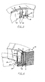
- Fig. 1 is an exploded view of a group of lens cells, 85, 86 and 87 constructed in accordance with the present invention.
- the individual lens cells, for example 85 are generally annular rings within which an optical element, for example, a lens 36, is disposed.
- flexures 22, 23 and 24 are provided, to which the lens 36 is bonded.
- the construction and use of the flexures 22, 23 and 24 are explained hereinbelow in reference to Figs. 2-5.
- the lens cell 85 also has precision machined surfaces 13-18 on its top.
- the machined surfaces are so located that they match precision machined surfaces on the bottom of lens cell 86.
- six precision machined surfaces 13-18 are shown in Fig. 1, there may be any number in excess of three. In this way cells can be rotated with respect to each other through small angles, such as 60 in the case where six precision machined surfaces are provided. By rotating select cells with respect to each other, the wavefront emanating from a series of lenses constrained within cells can be selectively changed. The method whereby a wavefront is adjusted is more fully explained in reference to Figs. 10 and 11.
- the precision machined surfaces 13-18 are in a plane which is perpendicular to the optical axis of the lens 36 contained in the cell 85.
- the distance from that plane to the vertex of the lens 36 is known. In this manner the verteces of lenses in adjoining cells can be established during precision machining of the lens cells.
- the outer diameter 35 of the lens cell 85 is also precision machined with respect to the lens 36 contained therein.
- the outer diameter 35 is symmetrical about the optical axis of the lens 36.
- the outer diameter 35 of lens cell 85 is equal to that of all the other lens cells in an assembly.
- Circumferential channel 95 is useful with the apparatus shown hereinbelow in Fig. 16 to provide for translational movements of one cell with respect to the other cells during the stacking of cells into a lens assembly.
- Holes 30-35 and dowels 10-12 are used in an epoxy pinning technique to bond cells 85, 86 and 87 together into a unitary, rigid assembly of cells.
- holes 31, 33 and 35 are adapted to hold dowels 10-12. This can be done, for example, by providing external threads on the dowels 10-12 which are threaded into tapped holes 31, 33 and 35. Bores through cells 86 and 87 are located so as to receive the dowels 10-12 extending from the top surface of cell 85 when cells 86 and 87 are stacked on cell 85. Epoxy, not shown, is then disposed between the dowels 10-12 and the corresponding bores in cells 86 and 87 to complete the epoxy bonding of cells 85, 86 and 87. This technique is more fully described hereinbelow in reference to Fig. 10.
- Fig. 2A shows an embodiment of a flexure in accordance with the present invention.
- the flexure 22 is integral with the inner wall of the lens cell 85. Extending radially inward from the flexure 22, and attached thereto, is the lens seat 29.
- the lens seat 29 has a trough 38 formed therein which serves as a receptacle for the adhesive as described hereinbelow in reference to Fig. 3 and establishes a specific bondline thickness.
- the flexure 22 is formed by, for example, wire electron discharge machining or milling a slot 42 into the wall of the lens cell 85. Such a slot 42 is radially located at a depth 'd' in the inner wall of the lens cell 85. The slot 42 begins at one end of the lens seat 29 and describes an arc of length 'a' about the center of the lens cell 85. The width of the finished flexure 22 is 'w' as shown.
- Fig. 2B shows the manner in which the lens 36 is bonded to the flexure 22.
- Adhesive such as EC 1838, available from the 3M Corporation, is placed in the trough so as to bond the lens 36 to the lens seat 29.
- the trough is sized to establish a bondline of cement which will withstand the stresses imparted to it during temperature excursions as described hereinbelow.
- There adhesive is placed in the trough 38 such that when the lens 36 is bonded to the seat 29 the excess adhesive does not overflow the seat 29 and create a fillet.
- the radius of curvature of the seat surface 39 may match the curvature of the lens 36 to which it is bonded. For large radii lenses the match between the radius of curvature of the lens 36 and the seat surface 39 diminishes in importance and can be machined at an angle with the center of the bondline forming a tangent to the lens curvature.
- the lens 36 is bonded to the lens cell 85 in the following manner.
- Adhesive 40 is placed in the trough 38 of the seat 29. This process is carried out for each of the flexures 22, 23 and 24 of Fig. 1.
- the lens 36 is then placed into the lens cell and pressed down onto the lens seat 29 such that the excess adhesive 40 is extruded from the trough 38 radially outward between the lens 36 and the seat surface 39.
- the lens 36 is centered in any convenient manner such that the outside diameter of the lens 36 is substantially concentric with the inside diameter of the lens cell 85.
- This assembly is performed at an ambient datum temperature, preferably the temperature at which the assembly will be operating.
- the lens seat 29 remains substantially fixed with respect to the lens 36.
- the arm 25 of the flexure 22 flexes. That is, the arm 25 moves such that the flexure slot width, f, increases.
- the flexure 22 returns to its original configuration and the lens 36 is retained in its original position, centered within the lens cell 22.
- lens 36 or adhesive layer 40 reach the allowable stress limits of their respective materials.
- the lens 36 Conversely, as the ambient temperature falls below the datum temperature the diameter of the lens cell 85 contracts, the lens 36 also contracts but to a lesser degree than the lens cell 85. Consequently the flexure arm flexes 25 such that the flexure slot width. f, decreases. As in the case of increasing temperature the lens seat 29 retains its spatial orientation with respect to the lens 36 and the integrity of the adhesive layer 40 is retained. In this way, when the temperature returns to the datum temperature the lens 36 is in the same orientation with respect to the lens cell 85 as when it was fabricated.
- the adhesive layer 40 has a large enough area so that it is not deformed or broken by this stress. In addition, the shape and location of the adhesive layer 40 will not cause a distortion of the transmitted wavefront in the vicinity of the bondline.
- Fig- 3 shows another form of the flexure of Figs. 2A and 2B.
- the flexure arm 25 is of two widths. W 1 and W 2 .
- W 1 is the width of the flexure arm 25 formed in the manner described in reference to Fig, 2A.
- W 2 is a narrower width than W 1 and is formed by, for example, machining down the narrow section 41 of the flexure arm 25.
- the narrow section 41 of the flexure arm 25 extends from the edge of the lens seat 29 a distance 'a', along the length of the flexure arm 25, The purpose of the narrow section 41 is to further reduce the stress experienced by the adhesive layer 40 shown in Fig. 2B.
- the flexure arm 25 flexes and a slight torsional stress is introduced to the adhesive layer 40 at the lens seat 39. This stress is as shown by the arrow 43 in Fig. 26.
- the narrow section 41 of the flexure arm 25 of Fig. 3 reduces the torsional stress by allowing the section of the flexure arm containing the lens seat 29 to rotate relative to the rest of the flexure arm 25, thus substantially maintaining the orientation of the lens 36 to the seat surface 39 while maintaining the stiffness of the flexure arm 25 in the axial direction.
- the flexure 52 is fabricated by machining, for example, radial shots, on either side of the lens seat 29, a distance ti into the wall of the lens cell 85.
- One such radial slot is shown at 44.
- Two axial slots, 48 and 50, are then formed.
- One axial slot. 50 is formed midway between the inner diameter of the lens cell 85 and the end of radial slot 44. It begins at the bottom of the lens cell 85, runs parallel to the inner diameter of the lens cell 85, and extends to within a distance t 2 of the top of the lens cell.
- the second axial slot is parallel to the first, begins at the end of radial slot 44 and at the top of the lens cell and extends to within the distance t 3 of the bottom of the lens cell.
- the operation of the flexure 52 of Fig. 4 is equivalent to that described for the flexure 22 of Figs. 2A and 2B.
- the flexure 52 moves in or out relative to the lens cell 20 to compensate for different thermal growth rates of the lens 36 and lens cell 20. In this way there is no change in the orientation of the lens 36 to the lens seat surface 39 when the lens cell/lens assembly returns to a predetermined datum temperature following temperature excursions.
- FIGs. 5A-5C Another form of the flexure 22, in accordance with the present invention, is shown in Figs. 5A-5C.
- a peripheral bondline 45 is formed between the flexure arm 25 and the diameter of the lens 36.
- a projection land 37 can be provided so as to maintain a clearance between the lens 36 and the inner diameter of the lens cell 85.
- Fig. 58 is a cross-section of a flexure arm 25 without the projection land shown in Fig. 5A. To bond the lens 36 to the flexure arm 25 the lens is held, in any convenient manner, adjacent to the hole 35 in the flexure arm.
- Injection means are then inserted into port 43 and a thixotropic, or viscous, cement is injected through the hold 35 to form a cement bondline 45 between the lens 36 and the flexure arm 25.
- a projection land 37 is provided, as shown in Fig. 5C.
- Thixotropic cement injected through the hole 35, forms a bondline 45 between the projection land 37 and the lens 36. It can be understood by those skilled in the art that the thickness shown as 'b' of the bondline 45 is established by the clearance between the lens 36 and flexure arm 25 in Fig. 5B or the lens 36 and projection land 37 in Fig. 3C.
- the bondline 45 in the flexures 22 of Figs. 5B and 5C is in tension or compression during temperature excursions above or below the datum temperature respectively. This is due to the fact that as the temperature increases above the datum point, the lens cell 85 expands to a greater extent that the lens 36. As explained hereinabove in reference to Figs. 2A and 2B the flexure arm 25 flexes to maintain the bondline 45 to the lens 36. This flexing, however, is not perfect and a small amount of tension is introduced in the bondline 45. Conversely, when the ambient temperature drops below the datum temperature, the diameter of the lens cell 85 contracts while the lens 36 also contracts, but to a lesser degree. Accordingly, a degree of compression is introduced to the cement bondline 45. In either case of increasing or decreasing temperature, the stiffness of the lens 36 to lens cell 85 is maintained in the axial direction.
- Fig. 6 shows a vacuum chuck 54 useful in the present invention for holding the lens 36 and lens cell 20 while it is being machined. The machining is carried out after the lens 36 has been assembled in the lens cell 20 in the manner described hereinabove.
- the vacuum chuck 54 has a base 60 which is attached to the spindle of a lathe, not shown.
- the lathe spindle is supported by an air bearing.
- Fig. 7 shows the interrelationship between a lens 36 and the vacuum chuck 54 to which it is held. For the purpose of illustration only, Fig. 7 shows the lens 36 without the lens cell to which it is attached.
- the lens 36 has two surfaces, 55 and 57, each of which has a radius of curvature R 1 and R 2 , respectively. So as to facilitate the seating and centering of the lens 36 onto the vacuum chuck 54, the chuck seat 56 is machined to have the same radius of curvature, R, , as lens surface 55. In this way lens surface 55 of the lens 36 and the chuck seat 56 are match-mated to each other. This minimizes hertzian seating stresses on the lens 36 as well as establishing the cordinates for matching the lens cell as described hereinbelow in reference to Fig. 9.
- the lens 36 is not a flat. Accordingly, the center of curvature of the chuck seat 56 is machined to be on the spin axis 64 of the vacuum chuck 54. By making the lens surface 55 match-mated to the chuck seat 56, the center of curvature 61 of lens surface 55 is always on the spin axis 64 of the vacuum chuck 54. The alignment of the center of curvature 63 of lens surface 57 to the spin axis 64 is explained hereinbelow in reference to Fig. 8. If the lens 36 is a flat, the chuck seat 56 is machined perpendicular to the spin axis 64 of the vacuum chuck 54.
- a vacuum is drawn, within the riser 58 through passage 62 by vacuum means, not shown.
- the lens 36 and cell 20 assembly are held to the vacuum chuck 54 but can be rotated radially relative to the vacuum chuck 54. This facilitates alignment of the optical axis of the lens 36 to the spin axis 64 of the vacuum chuck as explained hereinbelow in reference to Fig. 8.
- a strong vacuum is drawn in the vacuum chuck 54 to hold the lens 36 and lens cell 20 assembly during the machining of the lens cell 20 as described hereinbelow in reference to Fig. 9.
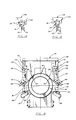
- Fig. 8 illustrates a manner in which the alignment of the optical axis 66 of the lens 36 to the spin axis 64 of the vacuum chuck 54 can be accomplished.
- the chuck 54 is shown mounted to the lathe spindle 70 through the chuck base 60. As described in reference to Fig. 7, the chuck base 60 is attached to a riser 58 which terminates in a chuck seat 56 upon which the lens 36 is seated.
- a TIR gauge 68 is placed on the surface of the lens 36 opposite the vacuum chuck 54. If, as shown in Fig. 8, the optical axis 66 of the lens 36 is not on the spin axis 64 of the vacuum chuck 54, the meter showing the run-out detected by the gauge 68 will be other than zero. The lens 36 can then be moved relative to the chuck seat 56 until the gauge readout 69 shows a minimum acceptable run-out. This puts the optical axis of the lens 36 on the spindle spin axis 64 and thus the vacuum chuck 54 as shown in Fig. 9.
- Fig. 9 also shows a tool bit 74, for example, a diamondpoint tool, and a tool controller 76.
- a tool bit 74 for example, a diamondpoint tool
- a tool controller 76 a tool controller 76. It can be appreciated by those skilled in the art that with the spin axis of the chuck 64 coincident with the optical axis 66 of the lens 36, the vertex 79 of the lens 36 is on the spin axis 64 of the vacuum chuck 54. Since the radius of curvature of the lens 36 is match mated to the radius of curvature of the chuck seat 56 and the apex 79 of the lens 36 is on the spin axis 64 of the vacuum chuck 54, the position of the vertex 79 is precisely known with respect to the vacuum chuck 54. The apex 79 is taken, then, as the (0,0,0) point for the tool 74. In this way all surfaces on the cell 20 can be machined precisely with respect to the vertex 79 and optical axis 64
- the outer diameter 33 of the lens cell 20 can be machined concentric about the optical axis 66 of the lens 36. Further, the precision machined surfaces 13-18 can be machined perpendicular to the optical axis of the lens 36 and located precisely with respect to the vertex 79 of the lens 36. All of the lens cells in an assembly of lens cells have their outer diameters machined to a common dimension. Thus, when the lens cells are stacked, in a manner described in reference to Fig. 10, the outer diameter of all the lens cells is made to be co-cylindrical to establish a common optical axis for the lenses in the assembly. The distance from the lens apexes to the cell surfaces perpendicular to the optical axis of the lens establishes the optical spacings when the lens cells are stacked and secured to each other.
- Fig. 10 shows a lens assembly 94.
- the lens cells 80-92 are stacked together and the wavefront directed therethrough is adjusted in a manner described hereinbelow in reference to Fig. 11.
- the optical characteristics of the wavefront can be changed by rotating, translating or axially moving selected ones of the lens cells with respect to others in the lens assembly 94.
- Selected ones of the lens cells can be moved axially with respect to the other lens cells in a lens assembly to correct for spherical aberrations. This can be accomplished by changing the thickness of shims 104 or through the use of the apparati shown in Figs. 18 and 19.
- Coma can be corrected by translating selected ones of the lens cells with respect to the other lens cells in a lens assembly as described herein in reference to Fig. 16. Further, by rotating selected ones of the lens cells with respect to others, astigmatism can be corrected.
- Fig. 10 Thirteen cells are shown bonded together in Fig. 10 as an example. It can be appreciated, however, that the cell-to-cell alignment and bonding method described herein is applicable to any plurality of cells.
- the cells 80-92 are then bonded together using, for example, dowels 102, plastic adhesive 100, and inter-cell seals.
- Figs. 14 and 15 show apparati useful in holding the lens cells in their desired spatial relation during the bonding process.
- the lens assembly 94 is an assembly of discrete groups, for example, 81-83, 83-85, 85-87, 87-89 and 89-91.
- the lens assembly 94 has a bottom lens cell 80 and a cap lens cell 92 between which are disposed the groups of lens cells.
- the groups of lens cells may consist of any desired number of lens cells in excess of two.
- Each group of lens cells has an anchor lens cells, for example 85, individual lens cells or cell, for example 86, and a top lens cell, for example 87.
- the top lens cell in a group also serves as an anchor lens cell if another group is stacked upon it.
- lens cell 87 serves as a top lens cell for the group 85-87 and as the anchor lens cell for the group 87-89.
- two or more dowels 102 are anchored in each anchor cell, 85 for example, and extend through the individual cell or cells and the top cell in the group.
- Pins 96 and 106 are shown to be conical.
- the conical shape of pins 96 and 106 allows them to be removed from their respective adhesive layers while retaining proper alignment to the remainder of the cells 81-91. This allows bottom lens cell 92 and cap lens cell 80 to be easily removed should they become damaged during assembly, transport or use.
- Fig. 11 shows an apparatus useful in accomplishing the optical alignment of the lens assembly 94 of Fig. 10.
- the lens assembly 94 is placed in a precision vee block 108 which is more clearly understood by reference to Fig. 12. It is made of a dimensionally stable material, such as granite, with the two faces 120 and 122 forming an angle 0 therebetween which is maintained for its entire length.
- the two faces, 120 and 122 of the vee block 108 are so formed that the contact between the outer diameter of each cell in the assembly 94 and the faces 120 and 122 falls on a line.
- the assembly 94 is placed in contact with the two faces 120 and 122 of the vee block 108, then transported by means, not shown, to the assembly station 114 as shown by the dotted lines 110 and 111.
- the vee block 108 is held to the assembly station 114 by the clamps 112 and 113.
- the lens assembly 94 rests on a floating mount 118 which is spaced away from the vee block 108.
- the floating mount 118 allows lateral translation and tilt of the lens assembly 94 with respect to the vee block faces 120 and 122 so as to ensure that the outer diameters of the lens cells in the lens assembly 94 just contact the faces 120 and 122. In this manner there is no distortion of the vee block 108 due to lens assembly 94 loading stresses and thus the optical axis of the lens assembly 94 is held parallel to the longitudinal axis of the vee block 108.
- Fig. 13 shows, in a sectional view, the floating mount 118 of Fig. 11.
- a float 130 is supported by a base 132.
- Pressurized air enters passage 142 which communicates with raceway 140 machined into bearing surface 148.
- Bearing surface 148 is machined with the same radius of curvature as journal surface 146 on float 130.
- the air entering raceway 140 thus forms a layer between the journal surface 146 and bearing surface 146.
- There are a plurality of passageways 144 which communicate through the float to a like plurality of openings in a channel 136 formed into the top of the float 130. Some of the air entering the raceway 140 passes through the passageways 144 and openings 134 to the channel 136.
- a wavefront, directed through it, can be inspected.
- a passageway is provided through the center of the floating mount 118 which is concentric about the passageway 124 provided through the base 116.
- Inspection means can be, for example, an interferometer located substantially beneath the passageway 124 in the base 114. In this way the wavefront can be examined to be sure that it conforms to the original optical design of the lens assembly.
- Correction can be made when necessary by making axial, rotational or translational movements of selected lens cells by, respectively, changing the shim 104 thickness between selected ones of the cells, by rotating selected ones of the cells with respect to the others in the lens assembly 94 and using the apparati and methods described hereinbelow in reference to Figs. 16 and 17.
- Fig. 16 shows an apparatus useful in holding lens cells in a lens assembly in their proper relation during initial aligning and testing.
- the lens cells 80-92 have circumferential channels 95 in their outer diameters. After the lens assembly 94 is assembled onto the assembly station 114, it may be necessary to translate the optical axis of one lens with respect to the others to achieve the requirements of the original optical design.
- Rails 159 and 160 are extended from the base 116 of the assembly station to the top of the vee block 108.
- a clamp support, 157 and 158 To each rail 159 and 160 is affixed a clamp support, 157 and 158 respectively. These clamp supports slide up and down the rails 159 and 160 and are held in position by knurled thumb screws 155 and 156 respectively.
- a mini-translation stage 163 and 164 At the end of each clamp support 157 and 158 is a mini-translation stage 163 and 164, respectively, each of which is translatable through the use of screws 165 and 166, respectively.
- Attached to each mini-translation stage 163 and 164 is a bayonet 161 and 162, respectively, which is sized to engage the circumferential channels 95 of the individual cells.
- the tips 172 and 173 are tapered to facilitate sliding the bayonets 161 and 162 between the lens assembly 94 and vee block faces 118 and 120 respectively.
- the cell translation device of Fig. 16 operates as follows: a selected lens cell is brought into contact with the two faces 118 and 120 of the vee block 108 by rubber band 174 acting in the circumferential channel 95 of the lens cell.
- the stages 163 and 164 and bayonets 161 and 162 move between the cell and the vee block faces 118 and 120. This allows the cell to be moved away from the vee block faces 118 and 120. Since the remaining cells are still held in contact with the vee block faces 118 and 120, the optical axis of the moved cell is translated relative to the optical axes of the remaining cells.
- Each individual cell is held in the desired position relative to the other cells by elastic bands 174 which are held at each end thereof by screws 169 and 170 affixed to blocks 167 and 168, respectively.
- the blocks 167 and 168 are attached to the assembly station 114.
- FIG. 17 An alternate lens translation technique is shown in Fig. 17 wherein a lens cell insert 175, having a tapered outside diameter 179, fits within a lens cell 180.
- the lens cell insert 175 has a lens 185 mounted through three flexures 176, 177 and 178 within it in the manner described hereinabove. Translation is accomplished by screws 184 acting through three holes 181, 182 and 183 to move the lens cell insert 175, hence the lens 185, in any desired direction. In this way the optical axis of the lens 185 can be moved relative to the optical axis of the other lenses in a lens assembly of which it is a part.
- the tapered outside diameter 179 of the lens cell insert 175 assures a downward force on the lens cell insert 175 which precludes introducing a tilt to the lens 185 during translation.
- Extending radially inward from lens cell 180 is lip 179.
- the top surface of lip 179 has a precision machined surface 195 which matches the precision machined surface 196 on the bottom of lens cell insert 175.
- the precision machined surfaces 195 and 196 establish the axial spacing of the lens cell insert 175, hence of the lens 185, with respect to the lens cell 180 and with respect to lens cells above or below lens cell 180 in a lens assembly.
- Fig. 18 shows a ball 186 disposed in a hole 187 in the top of a lens cell 20.
- the ball 186 is forced up when a tapered screw 188 is forced against it.
- a second lens cell, not shown, directly above the lens cell 20 will be forced upward when the ball 186 is so moved.
- Three such ball 186 and screw 188 arrangements are disposed at 120 ° intervals about the top of the lens cell 20.
- Fig. 19 shows a half ball 190 disposed on a tapered cantilevered arm 192.
- screw 194 As screw 194 is moved into the lens cell 20 it forces the tapered cantilevered arm 192 and ball 190 upward.
- a second lens cell, not shown, directly above the lens cell 20 will be forced upward when the ball 190 is so moved.
- Three such ball 190, arm 192 and screw 194 arrangements are disposed at 120 intervals about the top of the lens cell 20.
- the apparati shown in Figs. 18 and 19 for affecting axial movements of a lens cell can be used to tilt one lens cell, hence one lens, with respect to the others in an assembly. This is accomplished by moving the ball 186 of Fig. 18 or the ball 190 of Fig. 19 more or less than the other two balls in the apparati.
- the lens cells in the lens assembly 94 are epoxied together so as to form a unitary structure.
- the lens assembly can, at this point, be unstacked, then built up again, cell by cell, to facilitate the epoxying process. This unstacking and building up is done while retaining the as- adjusted wavefront.
- the epoxying process is accomplished by injecting plastic dowling cement 100, such as, for example, EPON 828, into the interface between the dowel 102 and the cell.
- the dowels 102 are anchored in one cell, such as cell 85, by, for example, screwing the dowel 102 into a tapped hole in the cell 85.
- the dowel then extends through holes in one or more cells, 86 and 87, above the anchor cell 85. It should be noted that the holes in the cells 86 and 87 are roughly aligned to the dowels 102 prior to the fine alignment of the assembly 94 as described in reference to Fig. 11.
- the lens assembly 94 can be assembled in a plurality of groups such as the group exemplified by cells 85-87. It can be understood by those skilled in the art that two or more continuous dowels, extending through all the cells 80-92, can be employed as an alternate to the above-described method.
- Fig. 14 shows an apparatus useful in holding the cells in a lens assembly in fixed spatial relation to one another during plastic dowling assembly.
- a lens assembly 94 is shown in contact with the two faces 118 and 120 of the vee block 108.
- the spring loaded screw 150 contacts the individual cells in the lens assembly 94 by being moved relative to a screw block 152 which is fixed to the assembly station 114 of Fig. 11. In this way the unsymmetrical forces generated during cement curing, which tend to decenter the lens axis from the vee block axis, are overcome.
- Fig. 15 illustrates an improvement to the device of Fig. 14 wherein a fork 154 is attached to the tip of the screw so that the force is more evenly distributed to the lens assembly 94.
Description
- The present invention relates to precision lens cells and, more particularly, to mounting such lens cells together into a unitary assembly.
- Optical designers are called upon to develop ever more accurate and powerful lens systems for such applications as photolithography equipment for the manufacture of semiconductor products. These lens systems are expected to maintain an extremely high level of performance under a multitude of environmental conditions during use, storage and shipping. In addition, they must be easily, rapidly and accurately assembled. The problem, therefore, is not only to develop the proper optical design but also to mount the lenses into a final assembly which remains true to the original design and is inexpensively accomplished.
- Lens mounting systems, in particular, such systems employing lens cells are explained in the technical literature, e.g., in Applied Optics and Optical Engineering, vol. VIII, Academic Press (1980) p. 31 ff.
- Lenses are commonly affixed within a lens cell which serves as an annular support for the lens. Typically, most lenses are held in lens cells with such mechanical devices as clips, clamps, screw- threaded retaining ring, epoxy, rolled lips or screws. The effects of thermal expansion and contraction when such a device is subjected to environmental temperature changes inevitably cause a change in the stress on the lens, manifested either as an unsymmetrical change of the clamping load on the element, possibly resulting in a translation of the element in its mounting within the cell, or an undesirable strain in the glass of the lens resulting in distortion of the transmitted wavefront.
- The lenses must, in turn, be assembled together so as to constitute a unitary optical assembly. Such an assembly must hold the lenses within tight tolerances so as to ensure proper axial and radial alignment, and must be easily and accurately assembled so as to reduce the manufacturing costs to a minimum.
- Lens assemblies may also be assembled together within a lens barrel which is an integral mechanical structure holding a series of lenses. It is used to position the lenses axially and radially with respect to each other, and to provide a means of interfacing the lens assembly with the system of which it is a part. Lens elements are radially positioned by the inner dimension of the barrel wall. The outer dimension of the lens elements are ground to fit ID of the barrel wall. The axial position of the lens elements is accomplished by cutting lens seats during assembly. The lens elements can then be constrained on the seats by epoxy, retaining rings, etc.
- Such barrel mounted lens assemblies have the disadvantages of being subject to thermally induced stresses to the barrel and/or lens, require specialized materials to minimize the effect of such stresses, are difficult to machine, particularly for multiple lenses, and are inherently inflexible after machining regarding adjustment of the relative location of the lens elements during assembly.
- Therefore, it is an object of the present invention to eliminate or ameliorate the foregoing disadvantages of the prior art. It is another object of the invention to provide a lens cell which is unaffected by large temperature excursions, when returned to the nominal operating temperature range. It is a further object of the invention to provide the same lens cell which can be used to quickly, easily and accurately assemble an optical system which achieves the original optical design requirements.
- The foregoing objects are solved with a precision lens cell according to claim 1, claim 7 or claim 9.
- The lens cell, with attached lens, is disposed on a vacuum chuck which is, in turn, mounted on a precision air bearing lathe spindle. The chuck seat is so machined in position to have the same radius of curvature as the lens to be seated on the chuck seat. This serves two purposes: to establish the coordinates of the cutting tool with respect to the vertex of the lens and to provide a good metal to glass seating surface so as to maintain a vacuum seal between the lens and the chuck.
- A high precision total indicator reading (TIR) type gauge on the surface of the lens opposite the vacuum chuck, assuming a curved surface, can be set to a minimum TIR by appropriate manipulation of the lens on the chuck seat with a minimum chuck vacuum force applied. This puts the outer lens radius of curvature, hence the optical axis of the lens, on the spin axis of the vacuum chuck. The cell surfaces, those perpendicular to the spin axis and the outer diameter of the lens cell, can be machined precisely perpendicular and concentric, respectively, to the spindle spin axis. It is the relationship from the lens vertexes to the surfaces of the cell perpendicular to the spin axis which establishes the spacings between the lenses when the lens cell assemblies are stacked and secured to each other. Accurate alignment of the optical axes of the lenses is achieved by making the outer diameters of all the lens cells equal and concentric about the optical axes of the lenses.
- The machined cells, with attached lenses, are then stacked and held in a precision vee block while tests are made to evaluate the transmitted wavefront. When the desired transmitted wavefront is achieved, through axial, radial or rotational movements of select cells, the cells are unstacked, then sequentially bonded together to form a rigid assembly as described hereinbelow.
- The first cell is positioned with two or more dowel pins projecting from its seating surface. The next cell is positioned with clearance holes around the pins. The vee block walls establish the centration of the cell, hence of the lenses. Plastic dowling cement is poured into the interface between the dowel and the cell with a seal between cells to prevent the cement from leaking and contacting the cell below. This is done one at a time until the entire assembly is epoxy-pinned together. Thus is formed a rigid, accurately positioned final lens assembly.
- There has thus been outlined rather broadly the more important features of the invention in order that the detailed description thereof that follows may be better understood, and in order that the present contribution to the art may be better appreciated. There are, of course, additional features of the invention which will be described hereinafter and which will form the subject of the claims appended hereto. Those skilled in the art will appreciate that the conception upon which the disclosure is based may readily be utilized as a basis for the designing of other assemblies for carrying out the several purposes of the invention. It is important, therefore, that the claims be regarded as including such equivalent assemblies as do not depart from the spirit and scope of the invention.
- Several embodiments of the invention have been chosen for purposes of illustration and description, and are shown in the accompanying drawings, forming a part of the specification.
-
- Fig. 1 shows an exploded view of a group of lens cells constructed in accordance with the present invention;
- Fig. 2A shows, schematically, an embodiment of a flexure constructed in accordance with the present invention;
- Fig. 2B is a top view of the flexure of Fig. 2;
- Fig. 3 is another form of the flexure of Fig. 2;
- Fig. 4 is another embodiment of a flexure constructed in accordance with the present invention;
- Fig. 5A is another embodiment of flexure constructed in accordance with the present invention;
- Fig. 5B is a cross-sectional view of the flexure of Fig. 5A with a projection land;
- Fig. 5C is a cross-sectional view of the flexure of Fig. 5A with a projection land;
- Fig. 6 is a vacuum chuck useful in fabricating a lens cell in accordance with the present invention;
- Fig. 7 shows a lens mounted on the vacuum chuck shown in Fig. 6;
- Fig. 8 shows, schematically, an apparatus useful in aligning the lens cell surfaces to the lens;
- Fig. 9 shows, schematically, the apparatus of Fig. 8 after the alignment of lens to lens cell is complete;
- Fig. 10 shows a lens assembly;
- Fig. 11 shows an apparatus useful in aligning the lens assembly of Fig. 10;
- Fig. 12 shows a vee block useful in the apparatus of Fig. 11;
- Fig. 13 shows, schematically, the floating mount useful in the apparatus of Fig. 11;
- Fig. 14 shows an apparatus useful in holding the cells in a lens assembly in proper relation during epoxy pinning;
- Fig. 15 shows another form of the apparatus of Fig. 14;
- Fig. 16 shows, in top view, a manner in which translation of the individual cells in the assembly of Fig. 10 can be accomplished;
- Fig. 17 shows, schematically, a manner in which translation of the individual cells in the assembly of Fig. 10 can be accomplished;
- Fig. 18 shows, schematically, a manner in which axial movement of the cells with respect to one another can be accomplished; and
- Fig. 19 shows, schematically, a manner in which axial movement of the cells with respect to one another can be accomplished.
- Fig. 1 is an exploded view of a group of lens cells, 85, 86 and 87 constructed in accordance with the present invention. The individual lens cells, for example 85, are generally annular rings within which an optical element, for example, a
lens 36, is disposed. - It is a characteristic of any solid material that it undergoes dimensional changes as the ambient temperature changes. Some materials undergo greater dimensional changes than others in response to temperature changes, that is, they have a different coefficient of thermal expansion. Any material, bonded to a material with a differing coefficient of expansion, will experience stress at the point of bonding during temperature excursions. Such stresses can cause permanent distortion or dimensional changes to the materials and can cause a change in the orientation of one material to the other. Such dimensional or orientation changes can be disastrous in optical systems where optic spacing, centration and wedge must be held to close tolerances.
- In the embodiment of the invention shown in Fig. 1, three cantilevered
flexures lens 36 is bonded. The construction and use of theflexures - The
lens cell 85 also has precision machined surfaces 13-18 on its top. The machined surfaces are so located that they match precision machined surfaces on the bottom oflens cell 86. It should be understood that while six precision machined surfaces 13-18 are shown in Fig. 1, there may be any number in excess of three. In this way cells can be rotated with respect to each other through small angles, such as 60 in the case where six precision machined surfaces are provided. By rotating select cells with respect to each other, the wavefront emanating from a series of lenses constrained within cells can be selectively changed. The method whereby a wavefront is adjusted is more fully explained in reference to Figs. 10 and 11. - As described hereinbelow in reference to Figs. 8 and 9, the precision machined surfaces 13-18 are in a plane which is perpendicular to the optical axis of the
lens 36 contained in thecell 85. In addition, the distance from that plane to the vertex of thelens 36 is known. In this manner the verteces of lenses in adjoining cells can be established during precision machining of the lens cells. - The
outer diameter 35 of thelens cell 85 is also precision machined with respect to thelens 36 contained therein. Theouter diameter 35 is symmetrical about the optical axis of thelens 36. In addition, theouter diameter 35 oflens cell 85 is equal to that of all the other lens cells in an assembly. Thus, when the outer diameters of all lens cells in an assembly are co-cylindrical, the optical axes of all the lenses contained within the lens cells in such an assembly are co-axial. The apparatus and method to achieve such symmetry is explained more fully below in reference to Figs. 8 and 9.Circumferential channel 95 is useful with the apparatus shown hereinbelow in Fig. 16 to provide for translational movements of one cell with respect to the other cells during the stacking of cells into a lens assembly. - Holes 30-35 and dowels 10-12 are used in an epoxy pinning technique to bond
cells holes cells cell 85 whencells cell 85. Epoxy, not shown, is then disposed between the dowels 10-12 and the corresponding bores incells cells - Fig. 2A shows an embodiment of a flexure in accordance with the present invention.
- The
flexure 22 is integral with the inner wall of thelens cell 85. Extending radially inward from theflexure 22, and attached thereto, is thelens seat 29. Thelens seat 29 has atrough 38 formed therein which serves as a receptacle for the adhesive as described hereinbelow in reference to Fig. 3 and establishes a specific bondline thickness. - The
flexure 22 is formed by, for example, wire electron discharge machining or milling aslot 42 into the wall of thelens cell 85. Such aslot 42 is radially located at a depth 'd' in the inner wall of thelens cell 85. Theslot 42 begins at one end of thelens seat 29 and describes an arc of length 'a' about the center of thelens cell 85. The width of thefinished flexure 22 is 'w' as shown. - Fig. 2B shows the manner in which the
lens 36 is bonded to theflexure 22. Adhesive, such as EC 1838, available from the 3M Corporation, is placed in the trough so as to bond thelens 36 to thelens seat 29. The trough is sized to establish a bondline of cement which will withstand the stresses imparted to it during temperature excursions as described hereinbelow. There adhesive is placed in thetrough 38 such that when thelens 36 is bonded to theseat 29 the excess adhesive does not overflow theseat 29 and create a fillet. It should be noted that the radius of curvature of theseat surface 39 may match the curvature of thelens 36 to which it is bonded. For large radii lenses the match between the radius of curvature of thelens 36 and theseat surface 39 diminishes in importance and can be machined at an angle with the center of the bondline forming a tangent to the lens curvature. - The
lens 36 is bonded to thelens cell 85 in the following manner.Adhesive 40 is placed in thetrough 38 of theseat 29. This process is carried out for each of theflexures lens 36 is then placed into the lens cell and pressed down onto thelens seat 29 such that theexcess adhesive 40 is extruded from thetrough 38 radially outward between thelens 36 and theseat surface 39. Thelens 36 is centered in any convenient manner such that the outside diameter of thelens 36 is substantially concentric with the inside diameter of thelens cell 85. This assembly is performed at an ambient datum temperature, preferably the temperature at which the assembly will be operating. - Referring now to Figs. 2A and 2B, the operation of the
flexure 22 can now be explained. As the ambient temperature cycles up or down, the relative diameter of thelens cell 85 and the diameter of thelens 36 changes. For example, consider the case where the coefficient of expansion of thelens cell 85 is considerably greater than that for thelens 36. As the temperature Increases from the datum temperature, thelens cell 85 expands and the inner diameter of thelens cell 85 becomes larger, At the same time thelens 36, hence its outside diameter, becomes larger but not to the same degree as thelens cell 85. In the prior art configuration, wherein no flexures are present, the lens would move relative to the lens seat causing the adhesive bond to shift or break due to the imposed stresses. In the embodiment of the present invention as shown in Figs. 2A and 26, thelens seat 29 remains substantially fixed with respect to thelens 36. As the inner diameter of thelens cell 85 expands away from thelens 36, thearm 25 of theflexure 22 flexes. That is, thearm 25 moves such that the flexure slot width, f, increases. When the temperature decreases and stabilizes at the datum temperature theflexure 22 returns to its original configuration and thelens 36 is retained in its original position, centered within thelens cell 22. At no time does theflexure arm 25,lens 36 oradhesive layer 40 reach the allowable stress limits of their respective materials. - Conversely, as the ambient temperature falls below the datum temperature the diameter of the
lens cell 85 contracts, thelens 36 also contracts but to a lesser degree than thelens cell 85. Consequently the flexure arm flexes 25 such that the flexure slot width. f, decreases. As in the case of increasing temperature thelens seat 29 retains its spatial orientation with respect to thelens 36 and the integrity of theadhesive layer 40 is retained. In this way, when the temperature returns to the datum temperature thelens 36 is in the same orientation with respect to thelens cell 85 as when it was fabricated. - As the flexure moves, a small torsional stress is imparted to the
adhesive layer 40 as shown by thearrow 43. Theadhesive layer 40 has a large enough area so that it is not deformed or broken by this stress. In addition, the shape and location of theadhesive layer 40 will not cause a distortion of the transmitted wavefront in the vicinity of the bondline. - Fig- 3 shows another form of the flexure of Figs. 2A and 2B. In the form of Fig. 3 the
flexure arm 25 is of two widths. W1 and W2. W1 is the width of theflexure arm 25 formed in the manner described in reference to Fig, 2A. W2, however, is a narrower width than W1 and is formed by, for example, machining down the narrow section 41 of theflexure arm 25. The narrow section 41 of theflexure arm 25 extends from the edge of the lens seat 29 a distance 'a', along the length of theflexure arm 25, The purpose of the narrow section 41 is to further reduce the stress experienced by theadhesive layer 40 shown in Fig. 2B. As thelens cell 22 expands relative to thelens 36 theflexure arm 25 flexes and a slight torsional stress is introduced to theadhesive layer 40 at thelens seat 39. This stress is as shown by thearrow 43 in Fig. 26. The narrow section 41 of theflexure arm 25 of Fig. 3 reduces the torsional stress by allowing the section of the flexure arm containing thelens seat 29 to rotate relative to the rest of theflexure arm 25, thus substantially maintaining the orientation of thelens 36 to theseat surface 39 while maintaining the stiffness of theflexure arm 25 in the axial direction. - Another form of the flexure is shown in cross-section in Fig. 4. The
flexure 52 is fabricated by machining, for example, radial shots, on either side of thelens seat 29, a distance ti into the wall of thelens cell 85. One such radial slot is shown at 44. Two axial slots, 48 and 50, are then formed. One axial slot. 50, is formed midway between the inner diameter of thelens cell 85 and the end of radial slot 44. It begins at the bottom of thelens cell 85, runs parallel to the inner diameter of thelens cell 85, and extends to within a distance t2 of the top of the lens cell. The second axial slot is parallel to the first, begins at the end of radial slot 44 and at the top of the lens cell and extends to within the distance t3 of the bottom of the lens cell. - The operation of the
flexure 52 of Fig. 4 is equivalent to that described for theflexure 22 of Figs. 2A and 2B. As the ambient temperature changes, theflexure 52 moves in or out relative to thelens cell 20 to compensate for different thermal growth rates of thelens 36 andlens cell 20. In this way there is no change in the orientation of thelens 36 to thelens seat surface 39 when the lens cell/lens assembly returns to a predetermined datum temperature following temperature excursions. - Another form of the
flexure 22, in accordance with the present invention, is shown in Figs. 5A-5C. In this form aperipheral bondline 45 is formed between theflexure arm 25 and the diameter of thelens 36. Aprojection land 37 can be provided so as to maintain a clearance between thelens 36 and the inner diameter of thelens cell 85. Fig. 58 is a cross-section of aflexure arm 25 without the projection land shown in Fig. 5A. To bond thelens 36 to theflexure arm 25 the lens is held, in any convenient manner, adjacent to thehole 35 in the flexure arm. Injection means, not shown, are then inserted intoport 43 and a thixotropic, or viscous, cement is injected through thehold 35 to form acement bondline 45 between thelens 36 and theflexure arm 25. A similar procedure is followed in the case where aprojection land 37 is provided, as shown in Fig. 5C. Thixotropic cement, injected through thehole 35, forms abondline 45 between theprojection land 37 and thelens 36. It can be understood by those skilled in the art that the thickness shown as 'b' of thebondline 45 is established by the clearance between thelens 36 andflexure arm 25 in Fig. 5B or thelens 36 andprojection land 37 in Fig. 3C. - The operation of the
flexures 22 of Figs. 5B and 5C are equivalent to that described in reference to theflexure 22 of Figs. 2A and 2B. - It should be noted that the
bondline 45 in theflexures 22 of Figs. 5B and 5C is in tension or compression during temperature excursions above or below the datum temperature respectively. This is due to the fact that as the temperature increases above the datum point, thelens cell 85 expands to a greater extent that thelens 36. As explained hereinabove in reference to Figs. 2A and 2B theflexure arm 25 flexes to maintain thebondline 45 to thelens 36. This flexing, however, is not perfect and a small amount of tension is introduced in thebondline 45. Conversely, when the ambient temperature drops below the datum temperature, the diameter of thelens cell 85 contracts while thelens 36 also contracts, but to a lesser degree. Accordingly, a degree of compression is introduced to thecement bondline 45. In either case of increasing or decreasing temperature, the stiffness of thelens 36 tolens cell 85 is maintained in the axial direction. - Referring now to Figs. 6-9, the apparatus and method for machining the precision surfaces and the outer diameter of the lens cell will be explained.
- Fig. 6 shows a
vacuum chuck 54 useful in the present invention for holding thelens 36 andlens cell 20 while it is being machined. The machining is carried out after thelens 36 has been assembled in thelens cell 20 in the manner described hereinabove. - The
vacuum chuck 54 has a base 60 which is attached to the spindle of a lathe, not shown. Preferably, the lathe spindle is supported by an air bearing. Attached to thebase 60, and disposed about the spin-axis 64 of thevacuum chuck 54, is acylindrical riser 58. At the top of theriser 58 is thechuck seat 56. - Fig. 7 shows the interrelationship between a
lens 36 and thevacuum chuck 54 to which it is held. For the purpose of illustration only, Fig. 7 shows thelens 36 without the lens cell to which it is attached. - The
lens 36 has two surfaces, 55 and 57, each of which has a radius of curvature R1 and R2, respectively. So as to facilitate the seating and centering of thelens 36 onto thevacuum chuck 54, thechuck seat 56 is machined to have the same radius of curvature, R, , aslens surface 55. In thisway lens surface 55 of thelens 36 and thechuck seat 56 are match-mated to each other. This minimizes hertzian seating stresses on thelens 36 as well as establishing the cordinates for matching the lens cell as described hereinbelow in reference to Fig. 9. - As shown in Fig. 7, the
lens 36 is not a flat. Accordingly, the center of curvature of thechuck seat 56 is machined to be on thespin axis 64 of thevacuum chuck 54. By making thelens surface 55 match-mated to thechuck seat 56, the center of curvature 61 oflens surface 55 is always on thespin axis 64 of thevacuum chuck 54. The alignment of the center of curvature 63 oflens surface 57 to thespin axis 64 is explained hereinbelow in reference to Fig. 8. If thelens 36 is a flat, thechuck seat 56 is machined perpendicular to thespin axis 64 of thevacuum chuck 54. - To retain the
lens 36 andcell 20 assembly to the vacuum chuck 54 a vacuum is drawn, within theriser 58 throughpassage 62 by vacuum means, not shown. When a low vacuum is drawn, thelens 36 andcell 20 assembly are held to thevacuum chuck 54 but can be rotated radially relative to thevacuum chuck 54. This facilitates alignment of the optical axis of thelens 36 to thespin axis 64 of the vacuum chuck as explained hereinbelow in reference to Fig. 8. Following alignment a strong vacuum is drawn in thevacuum chuck 54 to hold thelens 36 andlens cell 20 assembly during the machining of thelens cell 20 as described hereinbelow in reference to Fig. 9. - Fig. 8 illustrates a manner in which the alignment of the
optical axis 66 of thelens 36 to thespin axis 64 of thevacuum chuck 54 can be accomplished. - The
chuck 54 is shown mounted to thelathe spindle 70 through thechuck base 60. As described in reference to Fig. 7, thechuck base 60 is attached to ariser 58 which terminates in achuck seat 56 upon which thelens 36 is seated. A TIR gauge 68 is placed on the surface of thelens 36 opposite thevacuum chuck 54. If, as shown in Fig. 8, theoptical axis 66 of thelens 36 is not on thespin axis 64 of thevacuum chuck 54, the meter showing the run-out detected by the gauge 68 will be other than zero. Thelens 36 can then be moved relative to thechuck seat 56 until thegauge readout 69 shows a minimum acceptable run-out. This puts the optical axis of thelens 36 on thespindle spin axis 64 and thus thevacuum chuck 54 as shown in Fig. 9. - Fig. 9 also shows a tool bit 74, for example, a diamondpoint tool, and a
tool controller 76. It can be appreciated by those skilled in the art that with the spin axis of thechuck 64 coincident with theoptical axis 66 of thelens 36, thevertex 79 of thelens 36 is on thespin axis 64 of thevacuum chuck 54. Since the radius of curvature of thelens 36 is match mated to the radius of curvature of thechuck seat 56 and the apex 79 of thelens 36 is on thespin axis 64 of thevacuum chuck 54, the position of thevertex 79 is precisely known with respect to thevacuum chuck 54. The apex 79 is taken, then, as the (0,0,0) point for the tool 74. In this way all surfaces on thecell 20 can be machined precisely with respect to thevertex 79 andoptical axis 64 of thelens 36. - Referring to Fig. 1 and Fig. 9, it can be appreciated that the
outer diameter 33 of thelens cell 20 can be machined concentric about theoptical axis 66 of thelens 36. Further, the precision machined surfaces 13-18 can be machined perpendicular to the optical axis of thelens 36 and located precisely with respect to thevertex 79 of thelens 36. All of the lens cells in an assembly of lens cells have their outer diameters machined to a common dimension. Thus, when the lens cells are stacked, in a manner described in reference to Fig. 10, the outer diameter of all the lens cells is made to be co-cylindrical to establish a common optical axis for the lenses in the assembly. The distance from the lens apexes to the cell surfaces perpendicular to the optical axis of the lens establishes the optical spacings when the lens cells are stacked and secured to each other. - Fig. 10 shows a
lens assembly 94. The lens cells 80-92 are stacked together and the wavefront directed therethrough is adjusted in a manner described hereinbelow in reference to Fig. 11. Briefly, the optical characteristics of the wavefront can be changed by rotating, translating or axially moving selected ones of the lens cells with respect to others in thelens assembly 94. Selected ones of the lens cells can be moved axially with respect to the other lens cells in a lens assembly to correct for spherical aberrations. This can be accomplished by changing the thickness ofshims 104 or through the use of the apparati shown in Figs. 18 and 19. Coma can be corrected by translating selected ones of the lens cells with respect to the other lens cells in a lens assembly as described herein in reference to Fig. 16. Further, by rotating selected ones of the lens cells with respect to others, astigmatism can be corrected. - Thirteen cells are shown bonded together in Fig. 10 as an example. It can be appreciated, however, that the cell-to-cell alignment and bonding method described herein is applicable to any plurality of cells. The cells 80-92 are then bonded together using, for example, dowels 102,
plastic adhesive 100, and inter-cell seals. Figs. 14 and 15 show apparati useful in holding the lens cells in their desired spatial relation during the bonding process. - As can be seen in Fig. 10, the
lens assembly 94 is an assembly of discrete groups, for example, 81-83, 83-85, 85-87, 87-89 and 89-91. Thelens assembly 94 has abottom lens cell 80 and acap lens cell 92 between which are disposed the groups of lens cells. It should be understood that the groups of lens cells may consist of any desired number of lens cells in excess of two. - Each group of lens cells has an anchor lens cells, for example 85, individual lens cells or cell, for example 86, and a top lens cell, for example 87. The top lens cell in a group also serves as an anchor lens cell if another group is stacked upon it. For example,
lens cell 87 serves as a top lens cell for the group 85-87 and as the anchor lens cell for the group 87-89. As described hereinabove in reference to Fig. 1, two ormore dowels 102 are anchored in each anchor cell, 85 for example, and extend through the individual cell or cells and the top cell in the group. -
Pins pins bottom lens cell 92 andcap lens cell 80 to be easily removed should they become damaged during assembly, transport or use. - Fig. 11 shows an apparatus useful in accomplishing the optical alignment of the
lens assembly 94 of Fig. 10. Thelens assembly 94 is placed in a precision vee block 108 which is more clearly understood by reference to Fig. 12. It is made of a dimensionally stable material, such as granite, with the two faces 120 and 122 forming an angle 0 therebetween which is maintained for its entire length. The two faces, 120 and 122 of the vee block 108 are so formed that the contact between the outer diameter of each cell in theassembly 94 and thefaces - Returning now to Fig. 11, the
assembly 94 is placed in contact with the two faces 120 and 122 of the vee block 108, then transported by means, not shown, to the assembly station 114 as shown by the dottedlines 110 and 111. Thevee block 108 is held to the assembly station 114 by theclamps - The
lens assembly 94 rests on a floatingmount 118 which is spaced away from thevee block 108. The floatingmount 118 allows lateral translation and tilt of thelens assembly 94 with respect to the vee block faces 120 and 122 so as to ensure that the outer diameters of the lens cells in thelens assembly 94 just contact thefaces lens assembly 94 loading stresses and thus the optical axis of thelens assembly 94 is held parallel to the longitudinal axis of thevee block 108. - Fig. 13 shows, in a sectional view, the floating
mount 118 of Fig. 11. Afloat 130 is supported by abase 132. Pressurized air enterspassage 142 which communicates withraceway 140 machined into bearingsurface 148.Bearing surface 148 is machined with the same radius of curvature asjournal surface 146 onfloat 130. Theair entering raceway 140 thus forms a layer between thejournal surface 146 and bearingsurface 146. There are a plurality ofpassageways 144 which communicate through the float to a like plurality of openings in achannel 136 formed into the top of thefloat 130. Some of the air entering theraceway 140 passes through thepassageways 144 and openings 134 to thechannel 136. In this way a layer of air is formed between the top of thefloat 130 and the bottom cell of the lens assembly, not shown, which rests on the float. Thus, the lens assembly floats on the floatingmount 118 and may be frictionlessly moved laterally and tilted. - With the
lens assembly 94 held in the vee block 108 as shown in Fig. 11 a wavefront, directed through it, can be inspected. A passageway is provided through the center of the floatingmount 118 which is concentric about thepassageway 124 provided through thebase 116. In this manner, light can be directed through thelens assembly 94, floatingmount 118 andbase 116 to provide a passageway for light used in inspecting thelens assembly 94 during its assembly. Inspection means, not shown, can be, for example, an interferometer located substantially beneath thepassageway 124 in the base 114. In this way the wavefront can be examined to be sure that it conforms to the original optical design of the lens assembly. Correction can be made when necessary by making axial, rotational or translational movements of selected lens cells by, respectively, changing theshim 104 thickness between selected ones of the cells, by rotating selected ones of the cells with respect to the others in thelens assembly 94 and using the apparati and methods described hereinbelow in reference to Figs. 16 and 17. - As described in reference to Fig. 9, all of the cells in an assembly are machined such that the outside diameters are the same, and each cell outside diameter is concentric about the optical axis of the lens it contains. Thus, to align the optical axes of all of the lenses all that is required is to apply enough force to each lens cell to bring them just into contact with both
faces - Fig. 16 shows an apparatus useful in holding lens cells in a lens assembly in their proper relation during initial aligning and testing. As shown in Fig. 10, the lens cells 80-92 have
circumferential channels 95 in their outer diameters. After thelens assembly 94 is assembled onto the assembly station 114, it may be necessary to translate the optical axis of one lens with respect to the others to achieve the requirements of the original optical design. -
Rails base 116 of the assembly station to the top of thevee block 108. To eachrail rails clamp support mini-translation stage screws mini-translation stage bayonet circumferential channels 95 of the individual cells. Thetips bayonets lens assembly 94 and vee block faces 118 and 120 respectively. - The cell translation device of Fig. 16 operates as follows: a selected lens cell is brought into contact with the two faces 118 and 120 of the vee block 108 by rubber band 174 acting in the
circumferential channel 95 of the lens cell. By selectively movingscrews stages bayonets screws blocks blocks - An alternate lens translation technique is shown in Fig. 17 wherein a
lens cell insert 175, having a tapered outsidediameter 179, fits within a lens cell 180. Thelens cell insert 175 has a lens 185 mounted through threeflexures screws 184 acting through threeholes lens cell insert 175, hence the lens 185, in any desired direction. In this way the optical axis of the lens 185 can be moved relative to the optical axis of the other lenses in a lens assembly of which it is a part. The tapered outsidediameter 179 of thelens cell insert 175 assures a downward force on thelens cell insert 175 which precludes introducing a tilt to the lens 185 during translation. Extending radially inward from lens cell 180 islip 179. The top surface oflip 179 has a precision machinedsurface 195 which matches the precision machinedsurface 196 on the bottom oflens cell insert 175. The precision machinedsurfaces lens cell insert 175, hence of the lens 185, with respect to the lens cell 180 and with respect to lens cells above or below lens cell 180 in a lens assembly. - An alternate technique to move individual cells axially with respect to each other is as shown in Figs. 18 and 19.
- Fig. 18 shows a
ball 186 disposed in ahole 187 in the top of alens cell 20. Theball 186 is forced up when atapered screw 188 is forced against it. A second lens cell, not shown, directly above thelens cell 20 will be forced upward when theball 186 is so moved. Threesuch ball 186 and screw 188 arrangements are disposed at 120° intervals about the top of thelens cell 20. - Fig. 19 shows a
half ball 190 disposed on a tapered cantileveredarm 192. Asscrew 194 is moved into thelens cell 20 it forces the tapered cantileveredarm 192 andball 190 upward. A second lens cell, not shown, directly above thelens cell 20 will be forced upward when theball 190 is so moved. Threesuch ball 190,arm 192 and screw 194 arrangements are disposed at 120 intervals about the top of thelens cell 20. - The apparati shown in Figs. 18 and 19 for affecting axial movements of a lens cell can be used to tilt one lens cell, hence one lens, with respect to the others in an assembly. This is accomplished by moving the
ball 186 of Fig. 18 or theball 190 of Fig. 19 more or less than the other two balls in the apparati. - When the
lens assembly 94 is properly adjusted so as to provide the desired wavefront, the lens cells in thelens assembly 94 are epoxied together so as to form a unitary structure. It should be noted that the lens assembly can, at this point, be unstacked, then built up again, cell by cell, to facilitate the epoxying process. This unstacking and building up is done while retaining the as- adjusted wavefront. Referring to Fig. 10 it can be seen that the epoxying process is accomplished by injectingplastic dowling cement 100, such as, for example, EPON 828, into the interface between thedowel 102 and the cell. Aseal 98, between cells, prevents thecement 100 from leaking and contacting the cell below. Thedowels 102 are anchored in one cell, such ascell 85, by, for example, screwing thedowel 102 into a tapped hole in thecell 85. The dowel then extends through holes in one or more cells, 86 and 87, above theanchor cell 85. It should be noted that the holes in thecells dowels 102 prior to the fine alignment of theassembly 94 as described in reference to Fig. 11. By doweling 3 to 5 cells together in the above-described manner, thelens assembly 94 can be assembled in a plurality of groups such as the group exemplified by cells 85-87. It can be understood by those skilled in the art that two or more continuous dowels, extending through all the cells 80-92, can be employed as an alternate to the above-described method. - Fig. 14 shows an apparatus useful in holding the cells in a lens assembly in fixed spatial relation to one another during plastic dowling assembly. A
lens assembly 94 is shown in contact with the two faces 118 and 120 of thevee block 108. The spring loadedscrew 150 contacts the individual cells in thelens assembly 94 by being moved relative to ascrew block 152 which is fixed to the assembly station 114 of Fig. 11. In this way the unsymmetrical forces generated during cement curing, which tend to decenter the lens axis from the vee block axis, are overcome. - Fig. 15 illustrates an improvement to the device of Fig. 14 wherein a
fork 154 is attached to the tip of the screw so that the force is more evenly distributed to thelens assembly 94. - There has thus been described a mounting device for optical elements which mounts such elements together in a unitary assembly. Such assembly is unaffected by large temperature excursions and is quickly, easily and accurately assembled.
- While the present invention has been shown and described with reference to a preferred embodiment thereof, it will be understood by those skilled in the art that changes in form or detail may be made therein without departure from the scope of the invention. Accordingly, it is understood that the invention is to be broadly construed within the scope of the claims appended hereto.
Claims (20)
characterised in that
said end faces have three or more precision surfaces (13-18) disposed in said plane, and in that said holding means comprises flexure means (22,23,24) disposed on the innner wall of said annular member (20) having at least three arcuate cantilevered arms (25) integrally formed and regularly spaced in said annular member (20) for holding the vertex of said lens (36) with said lens attachment means (29,37) at a predetermined distance to said plane and concentric to said outer wall.
characterised in that
characterised in that
characterised in that
Applications Claiming Priority (2)
| Application Number | Priority Date | Filing Date | Title |
|---|---|---|---|
| US06/818,925 US4733945A (en) | 1986-01-15 | 1986-01-15 | Precision lens mounting |
| US818925 | 1992-01-10 |
Publications (3)
| Publication Number | Publication Date |
|---|---|
| EP0230277A2 EP0230277A2 (en) | 1987-07-29 |
| EP0230277A3 EP0230277A3 (en) | 1989-11-15 |
| EP0230277B1 true EP0230277B1 (en) | 1995-08-30 |
Family
ID=25226777
Family Applications (1)
| Application Number | Title | Priority Date | Filing Date |
|---|---|---|---|
| EP87100468A Expired - Lifetime EP0230277B1 (en) | 1986-01-15 | 1987-01-15 | Precision lens mounting |
Country Status (4)
| Country | Link |
|---|---|
| US (1) | US4733945A (en) |
| EP (1) | EP0230277B1 (en) |
| KR (1) | KR940008680B1 (en) |
| DE (1) | DE3751485T2 (en) |
Cited By (3)
| Publication number | Priority date | Publication date | Assignee | Title |
|---|---|---|---|---|
| JP2000227533A (en) * | 1999-02-03 | 2000-08-15 | Carl Zeiss Stiftung Trading As Carl Zeiss | Assembly with optical device and mount |
| EP2444829A1 (en) * | 2006-09-14 | 2012-04-25 | Carl Zeiss SMT GmbH | Optical element unit and method of supporting an optical element |
| US10216094B2 (en) | 2016-10-27 | 2019-02-26 | National Applied Research Laboratories | Support device and method for supporting lens and support component for supporting functional element |
Families Citing this family (103)
| Publication number | Priority date | Publication date | Assignee | Title |
|---|---|---|---|---|
| US4961115A (en) * | 1989-01-03 | 1990-10-02 | Eastman Kodak Company | Lens adjustment apparatus |
| JP2767468B2 (en) * | 1989-09-28 | 1998-06-18 | 京セラ株式会社 | Lens barrel |
| JPH0358609U (en) * | 1989-10-12 | 1991-06-07 | ||
| JPH03208008A (en) * | 1990-01-10 | 1991-09-11 | Brother Ind Ltd | Laser scanner device |
| JP2532200Y2 (en) * | 1990-05-25 | 1997-04-09 | 旭光学工業株式会社 | Support device for circular members |
| US5493452A (en) * | 1990-10-31 | 1996-02-20 | Olympus Optical Company Limited | Lens retaining barrel |
| US5249082A (en) * | 1991-05-08 | 1993-09-28 | Eastman Kodak Company | Exact constraint arrangement for and methods of mounting an element such as a lens |
| JPH0516126U (en) * | 1991-08-19 | 1993-03-02 | コニカ株式会社 | Lens holding device |
| US5428482A (en) * | 1991-11-04 | 1995-06-27 | General Signal Corporation | Decoupled mount for optical element and stacked annuli assembly |
| US5671088A (en) * | 1992-06-03 | 1997-09-23 | Leupold & Stevens, Inc. | Variable optical aiming devices |
| JPH08194145A (en) * | 1995-01-17 | 1996-07-30 | Asahi Optical Co Ltd | Lens supporting device |
| DE19825716A1 (en) * | 1998-06-09 | 1999-12-16 | Zeiss Carl Fa | Optical element and socket assembly |
| DE19859634A1 (en) * | 1998-12-23 | 2000-06-29 | Zeiss Carl Fa | Optical system, in particular projection exposure system for microlithography |
| US6239924B1 (en) | 1999-08-31 | 2001-05-29 | Nikon Corporation | Kinematic lens mounting with distributed support and radial flexure |
| US6650412B1 (en) * | 1999-09-10 | 2003-11-18 | Kaiser Optical Systems | Thermal compensation for optical apparatus |
| US6525802B1 (en) | 1999-11-05 | 2003-02-25 | Nikon Corporation | Kinematic mounted reference mirror with provision for stable mounting of alignment optics |
| JP4809987B2 (en) * | 2000-03-30 | 2011-11-09 | キヤノン株式会社 | Support structure for optical element, exposure apparatus using the same, and method for manufacturing semiconductor device |
| JP4945845B2 (en) * | 2000-03-31 | 2012-06-06 | 株式会社ニコン | An optical element holding device, a lens barrel, an exposure apparatus, and a microdevice manufacturing method. |
| DE10030495A1 (en) | 2000-06-21 | 2002-01-03 | Zeiss Carl | Method for connecting a plurality of optical elements to a base body |
| US6577457B1 (en) | 2000-08-10 | 2003-06-10 | Nikon Corporation | Catadioptric lens barrel structure having a kinematic alignment structure and method for aligning two planar surfaces |
| US6639740B1 (en) | 2000-08-10 | 2003-10-28 | Nikon Corporation | Catadioptric lens barrel structure having a plurality of split lens barrels and a support structure supporting the split lens barrels |
| US6473245B1 (en) | 2000-08-10 | 2002-10-29 | Nikon Corporation | Catadioptric lens barrel structure having a plurality of support platforms and method of making the same |
| US6400516B1 (en) | 2000-08-10 | 2002-06-04 | Nikon Corporation | Kinematic optical mounting |
| US6574053B1 (en) | 2000-08-10 | 2003-06-03 | Nikon Corporation | Kinematic alignment structure for placement between components axially aligned in a cylindrical body |
| DE10046379A1 (en) | 2000-09-20 | 2002-03-28 | Zeiss Carl | System for the targeted deformation of optical elements |
| US6717159B2 (en) | 2000-10-18 | 2004-04-06 | Nikon Corporation | Low distortion kinematic reticle support |
| DE10053899A1 (en) | 2000-10-31 | 2002-05-08 | Zeiss Carl | Bearing system for precision optical system minimises distortion from dynamic forces |
| WO2002039491A1 (en) * | 2000-11-10 | 2002-05-16 | Nikon Corporation | Optical device, exposure device and device manufacturing method |
| US6439139B1 (en) * | 2000-11-17 | 2002-08-27 | Owens Corning Fiberglas Technology, Inc. | Method for recycling building materials |
| DE10106605A1 (en) | 2001-02-13 | 2002-08-22 | Zeiss Carl | System for eliminating or at least damping vibrations |
| DE10115914A1 (en) | 2001-03-30 | 2002-10-02 | Zeiss Carl | Device for storing an optical element in an optical system |
| DE10115915A1 (en) | 2001-03-30 | 2002-10-02 | Zeiss Carl | Device for adjusting devices and adjusting adjustment paths |
| US7014328B2 (en) | 2001-04-12 | 2006-03-21 | Carl Zeiss Smt Ag | Apparatus for tilting a carrier for optical elements |
| US6674584B2 (en) * | 2001-07-03 | 2004-01-06 | Pts Corporation | Optical surface-mount lens cell |
| US6625342B2 (en) * | 2001-07-03 | 2003-09-23 | Network Photonics, Inc. | Systems and methods for overcoming stiction using a lever |
| DE10140608A1 (en) * | 2001-08-18 | 2003-03-06 | Zeiss Carl | Device for adjusting an optical element |
| DE10156884A1 (en) | 2001-11-20 | 2003-05-28 | Zeiss Carl Smt Ag | Arrangement for mounting holder for optical element, especially for semiconductor microlithography, has magnetic flux in component inhibited by lower permeability region |
| JP2003241049A (en) * | 2002-02-22 | 2003-08-27 | Nikon Corp | Optical element holding method, optical element polishing method, and optical element filming method |
| WO2003090265A1 (en) * | 2002-04-22 | 2003-10-30 | Nikon Corporation | Support apparatus, optical apparatus, light exposure apparatus, and method for producing device |
| US7245361B2 (en) * | 2002-06-04 | 2007-07-17 | Nikon Corporation | Method for evaluating refractive index homogeneity of optical member |
| DE10228053B4 (en) * | 2002-06-19 | 2006-06-14 | Carl Zeiss Jena Gmbh | Element and method for its production, in which two bodies positioned with respect to at least one adjusting axis are connected to one another in a material-locking manner |
| US6873478B2 (en) * | 2002-06-21 | 2005-03-29 | Nikon Corporation | Kinematic lens mount with reduced clamping force |
| JP4565261B2 (en) * | 2002-06-24 | 2010-10-20 | 株式会社ニコン | Optical element holding mechanism, optical system barrel, and exposure apparatus |
| US6922293B2 (en) | 2002-07-02 | 2005-07-26 | Nikon Corporation | Kinematic optical mounting assembly with flexures |
| AU2003294125A1 (en) * | 2002-12-23 | 2004-07-14 | Bae Systems Plc | Deformable mirror |
| US7740363B2 (en) * | 2002-12-23 | 2010-06-22 | Bae Systems Plc | Deformable-mirror holder |
| WO2004057406A2 (en) * | 2002-12-23 | 2004-07-08 | Bae Systems Plc | Deformable-mirror cooling |
| KR101281357B1 (en) † | 2003-06-06 | 2013-07-02 | 가부시키가이샤 니콘 | Optical element holding device, lens barrel, exposing device, and device producing method |
| DE10331390A1 (en) | 2003-07-11 | 2005-01-27 | Carl Zeiss Smt Ag | Aspherical surface production process for optical elements, comprises placing element in mould, introducing medium, and spherically working deformed optical medium |
| DE10339362A1 (en) * | 2003-08-27 | 2005-03-24 | Carl Zeiss Smt Ag | Device for preventing the creeping of an optical element |
| US6816325B1 (en) | 2003-09-11 | 2004-11-09 | Carl Zeiss Smt Ag | Mounting apparatus for an optical element |
| US7760327B2 (en) | 2003-10-02 | 2010-07-20 | Carl Zeiss Smt Ag | Reflecting optical element with eccentric optical passageway |
| JP4237755B2 (en) * | 2003-10-02 | 2009-03-11 | カール・ツァイス・エスエムティー・アーゲー | Optical subassemblies and projection objectives in semiconductor lithography. |
| US7085080B2 (en) | 2003-12-06 | 2006-08-01 | Carl Zeiss Smt Ag | Low-deformation support device of an optical element |
| US7369332B2 (en) | 2004-04-13 | 2008-05-06 | Carl Zeiss Smt Gmbh | Closing module for an optical arrangement |
| DE102004018659A1 (en) * | 2004-04-13 | 2005-11-03 | Carl Zeiss Smt Ag | Termination module for an optical arrangement |
| JP2009501350A (en) | 2005-07-14 | 2009-01-15 | カール・ツァイス・エスエムティー・アーゲー | Optical element |
| JP5620638B2 (en) * | 2005-07-19 | 2014-11-05 | カール・ツァイス・エスエムティー・ゲーエムベーハー | Optical imaging device |
| WO2007020067A1 (en) | 2005-08-16 | 2007-02-22 | Carl Zeiss Smt Ag | Immersion lithography objective |
| EP1882983A1 (en) * | 2006-07-25 | 2008-01-30 | Carl Zeiss SMT AG | Gravity compensating support for an optical element |
| DE102006038634A1 (en) * | 2006-08-17 | 2008-02-21 | Carl Zeiss Smt Ag | Holding device for an optical element with support force compensation |
| US8441747B2 (en) * | 2006-09-14 | 2013-05-14 | Carl Zeiss Smt Gmbh | Optical module with minimized overrun of the optical element |
| WO2008119386A1 (en) | 2007-03-30 | 2008-10-09 | Carl Zeiss Smt Ag | Support for a component of an optical device |
| WO2008133234A1 (en) * | 2007-04-23 | 2008-11-06 | Nikon Corporation | Optical element holding device, lens barrel, exposure device, and device manufacturing method |
| WO2008146655A1 (en) * | 2007-05-25 | 2008-12-04 | Nikon Corporation | Optical element holding apparatus, lens barrel, exposure apparatus and device manufacturing method |
| DE102009031690A1 (en) * | 2009-06-26 | 2010-09-23 | Carl Zeiss Laser Optics Gmbh | Optical arrangement, has blade springs connected together by connection section such that springs are linked together during radial force effect on contact point, where connection section is moved relative to frame |
| DE102009045163B4 (en) * | 2009-09-30 | 2017-04-06 | Carl Zeiss Smt Gmbh | Optical arrangement in a microlithographic projection exposure apparatus |
| GB2481476B (en) * | 2010-11-29 | 2012-07-04 | Ophir Optronics Ltd | Centring method for optical elements |
| DE102010021539B4 (en) | 2010-05-19 | 2014-10-09 | Carl Zeiss Smt Gmbh | Projection lens with apertures |
| US8919724B2 (en) * | 2010-08-24 | 2014-12-30 | Raytheon Company | Mount for cryogenic fast switching mechanism |
| US8100377B1 (en) | 2010-09-02 | 2012-01-24 | The Boeing Company | Pin mount assemblies and methods |
| US8507839B2 (en) | 2010-09-22 | 2013-08-13 | Exelis, Inc. | Image intensifier tube with a mounting surface |
| CN102590974B (en) * | 2011-01-14 | 2014-02-19 | 上海微电子装备有限公司 | Position fine adjustment device and objective lens adopting same |
| USD666229S1 (en) | 2011-03-16 | 2012-08-28 | Satisloh North America, Inc. | Optic device securing structure |
| USD666230S1 (en) * | 2011-03-16 | 2012-08-28 | Satisloh North America, Inc. | Optic device securing structure |
| US9308617B2 (en) * | 2011-03-16 | 2016-04-12 | Satisloh North America, Inc. | Securing structure for optic device |
| USD666231S1 (en) * | 2011-03-16 | 2012-08-28 | Satisloh North America, Inc. | Optic device securing structure |
| USD666228S1 (en) | 2011-03-16 | 2012-08-28 | Satisloh North America, Inc. | Optic device securing structure |
| US9417422B2 (en) * | 2011-08-23 | 2016-08-16 | Bae Systems Information And Electronic Systems Integration Inc. | Rigid adaptor ring for CTE mismatched optical device components |
| FR2986336B1 (en) * | 2012-01-27 | 2014-03-21 | Centre Nat Rech Scient | DEVICE FOR FASTENING AN OPTICAL MEMBER, FIXING SYSTEM AND CRYOGENIC DEVICE COMPRISING SUCH A DEVICE, METHOD FOR MANUFACTURING SUCH DEVICE AND CORRESPONDING FIXING METHOD |
| CN102854597A (en) * | 2012-08-29 | 2013-01-02 | 中国科学院长春光学精密机械与物理研究所 | High-precision supporting structure of optical element in photo-etching objective lens |
| CN102854596A (en) * | 2012-08-29 | 2013-01-02 | 中国科学院长春光学精密机械与物理研究所 | High-precision supporting structure of optical lens |
| CN103389558B (en) * | 2013-07-29 | 2015-12-02 | 中国科学院长春光学精密机械与物理研究所 | Lens axial adjusting device in lithographic objective |
| US9244245B2 (en) | 2013-11-08 | 2016-01-26 | Institut National D'optique | Auto-centering of an optical element within a barrel |
| JP6096377B2 (en) * | 2014-03-28 | 2017-03-15 | 富士フイルム株式会社 | LENS DEVICE AND LENS DEVICE CORRECTION METHOD |
| JP5969728B2 (en) * | 2014-03-31 | 2016-08-17 | 富士フイルム株式会社 | Zoom lens device and control method thereof |
| EP3172607B1 (en) | 2014-07-25 | 2022-07-20 | Institut National d'Optique | Optical assemblies with tilt-controlled mounting of an optical element in a barrel |
| US10288095B2 (en) | 2014-09-22 | 2019-05-14 | Institut National D'optique | Mounting of an optical element in a barrel using a flexible ring |
| US9939604B2 (en) | 2015-03-31 | 2018-04-10 | Institut National D'optique | Optical assembly with translatable centered sleeve |
| DE102015115929B3 (en) * | 2015-09-21 | 2016-10-06 | Jenoptik Optical Systems Gmbh | Monolithic lens frame |
| CN105572043A (en) * | 2015-12-21 | 2016-05-11 | 中国科学院长春光学精密机械与物理研究所 | Flexible supporting device for testing optical uniformity |
| US20170363833A1 (en) * | 2016-06-17 | 2017-12-21 | Corning Incorporated | Polymer-free compliant optical member support |
| US10015378B2 (en) | 2016-09-15 | 2018-07-03 | Microsoft Technology Licensing, Llc | Kinematic mount for split camera |
| US20180239102A1 (en) * | 2017-02-20 | 2018-08-23 | Corning Incorporated | Optical mount |
| US10895711B2 (en) | 2017-06-28 | 2021-01-19 | Corning Incorporated | Polymer-free compliant optical member support |
| DE102017212950B4 (en) | 2017-07-27 | 2018-05-30 | Carl Zeiss Smt Gmbh | CLAMPING DEVICE, MACHINING AND / OR MEASURING MACHINE AND METHOD |
| JP6951967B2 (en) | 2017-12-28 | 2021-10-20 | 日本電産サンキョー株式会社 | Manufacturing method of lens unit and mold |
| DE102018103053B3 (en) | 2018-02-12 | 2018-10-11 | Jenoptik Optical Systems Gmbh | Space-optimized lens frame with elastic connection structures |
| JP2019168488A (en) * | 2018-03-22 | 2019-10-03 | セイコーエプソン株式会社 | Alignment mechanism, lens unit, projection optical system, and projector |
| KR20220016101A (en) * | 2019-06-05 | 2022-02-08 | 쉘터드 윙스, 인크. 디/비/에이 보텍스 옵틱스 | Diopter adjustment mechanism |
| GB2588160B (en) * | 2019-10-10 | 2022-09-21 | Univ Brunel | Adaptive precision chuck |
| DE102022205143A1 (en) | 2022-05-24 | 2023-11-30 | Carl Zeiss Smt Gmbh | Optical element as well as assembly and optical system with it |
| KR102577850B1 (en) * | 2023-02-21 | 2023-09-13 | 국방과학연구소 | Monolithic Flexure Hinge Mount for Optical section |
Family Cites Families (5)
| Publication number | Priority date | Publication date | Assignee | Title |
|---|---|---|---|---|
| NL161265C (en) * | 1974-02-15 | 1980-01-15 | Philips Nv | METHOD FOR CENTERING A LENS IN A VESSEL |
| US4239364A (en) * | 1978-10-23 | 1980-12-16 | Kiyoshi Doi | Camera body mount |
| JPS58178306A (en) * | 1982-04-14 | 1983-10-19 | Olympus Optical Co Ltd | Lens holder |
| JPS5919911A (en) * | 1982-07-27 | 1984-02-01 | Olympus Optical Co Ltd | Lens holding device and optical lens composite element |
| JPS5931914A (en) * | 1982-08-17 | 1984-02-21 | Olympus Optical Co Ltd | Lens holder |
-
1986
- 1986-01-15 US US06/818,925 patent/US4733945A/en not_active Expired - Fee Related
-
1987
- 1987-01-15 EP EP87100468A patent/EP0230277B1/en not_active Expired - Lifetime
- 1987-01-15 DE DE3751485T patent/DE3751485T2/en not_active Expired - Fee Related
- 1987-01-30 KR KR1019870000712A patent/KR940008680B1/en not_active IP Right Cessation
Cited By (4)
| Publication number | Priority date | Publication date | Assignee | Title |
|---|---|---|---|---|
| JP2000227533A (en) * | 1999-02-03 | 2000-08-15 | Carl Zeiss Stiftung Trading As Carl Zeiss | Assembly with optical device and mount |
| EP2444829A1 (en) * | 2006-09-14 | 2012-04-25 | Carl Zeiss SMT GmbH | Optical element unit and method of supporting an optical element |
| US9134501B2 (en) | 2006-09-14 | 2015-09-15 | Carl Zeiss Smt Gmbh | Optical element unit and method of supporting an optical element |
| US10216094B2 (en) | 2016-10-27 | 2019-02-26 | National Applied Research Laboratories | Support device and method for supporting lens and support component for supporting functional element |
Also Published As
| Publication number | Publication date |
|---|---|
| DE3751485D1 (en) | 1995-10-05 |
| KR880009283A (en) | 1988-09-14 |
| EP0230277A2 (en) | 1987-07-29 |
| KR940008680B1 (en) | 1994-09-24 |
| US4733945A (en) | 1988-03-29 |
| EP0230277A3 (en) | 1989-11-15 |
| DE3751485T2 (en) | 1996-02-22 |
Similar Documents
| Publication | Publication Date | Title |
|---|---|---|
| EP0230277B1 (en) | Precision lens mounting | |
| RU2364508C2 (en) | Alignment device for two shell moulds | |
| US9470870B2 (en) | Optical assemblies with tilt-controlled mounting of an optical element in a barrel | |
| EP0243893B1 (en) | Lens mount for, and method of mounting high resolution projection lenses | |
| US7715129B2 (en) | Method for aligning and assembling two lens pieces, and a machine to accomplish this task | |
| US10668678B2 (en) | Die tool, device and method for producing a lens wafer | |
| US4371233A (en) | Lens-applied optical fiber connector | |
| US4586787A (en) | Lens assembly | |
| US11320623B2 (en) | Centering of an optical element using edge contact mounting | |
| US11143838B2 (en) | Optical element retainers | |
| US4763417A (en) | Multi-coordinate probe | |
| Doel et al. | Assembly, alignment, and testing of the DECam wide field corrector optics | |
| JPS63202707A (en) | Precision lens mounting assembly and method and device for manufacturing precision lens cell assembly | |
| TWI471627B (en) | Lens module and method for assembly same | |
| Yoder Jr | Lens mounting techniques | |
| EP0525523B1 (en) | Arrangements for, methods of, and lenses configured to provide thermal compensation in lens element mounts | |
| US4545570A (en) | Gimbal fixture and assembly method | |
| CA1268366A (en) | Precision lens mounting | |
| EP0276900B1 (en) | Apparatus and method for aligning two surfaces | |
| US8139298B2 (en) | Optically measurable mounting structure | |
| Willey | Optical design for manufacture | |
| US6666588B1 (en) | Collimator array having precisely aligned optical beams and method of assembling same | |
| KR20230112888A (en) | A ring lens that improves assembly and its manufacturing method | |
| Jones | High performance lens mounting | |
| Zhang | Elastomeric mounting of collimating lenses in space solar telescope |
Legal Events
| Date | Code | Title | Description |
|---|---|---|---|
| PUAI | Public reference made under article 153(3) epc to a published international application that has entered the european phase |
Free format text: ORIGINAL CODE: 0009012 |
|
| AK | Designated contracting states |
Kind code of ref document: A2 Designated state(s): CH DE FR GB IT LI NL |
|
| PUAL | Search report despatched |
Free format text: ORIGINAL CODE: 0009013 |
|
| AK | Designated contracting states |
Kind code of ref document: A3 Designated state(s): CH DE FR GB IT LI NL |
|
| 17P | Request for examination filed |
Effective date: 19900515 |
|
| RAP1 | Party data changed (applicant data changed or rights of an application transferred) |
Owner name: SVG LITHOGRAPHY SYSTEMS, INC. |
|
| 17Q | First examination report despatched |
Effective date: 19920515 |
|
| GRAA | (expected) grant |
Free format text: ORIGINAL CODE: 0009210 |
|
| ITF | It: translation for a ep patent filed |
Owner name: STUDIO INGG. FISCHETTI & WEBER |
|
| AK | Designated contracting states |
Kind code of ref document: B1 Designated state(s): CH DE FR GB IT LI NL |
|
| REF | Corresponds to: |
Ref document number: 3751485 Country of ref document: DE Date of ref document: 19951005 |
|
| ET | Fr: translation filed | ||
| PLBE | No opposition filed within time limit |
Free format text: ORIGINAL CODE: 0009261 |
|
| STAA | Information on the status of an ep patent application or granted ep patent |
Free format text: STATUS: NO OPPOSITION FILED WITHIN TIME LIMIT |
|
| 26N | No opposition filed | ||
| PGFP | Annual fee paid to national office [announced via postgrant information from national office to epo] |
Ref country code: FR Payment date: 19961128 Year of fee payment: 11 |
|
| PGFP | Annual fee paid to national office [announced via postgrant information from national office to epo] |
Ref country code: GB Payment date: 19970106 Year of fee payment: 11 |
|
| PGFP | Annual fee paid to national office [announced via postgrant information from national office to epo] |
Ref country code: CH Payment date: 19970115 Year of fee payment: 11 |
|
| PGFP | Annual fee paid to national office [announced via postgrant information from national office to epo] |
Ref country code: NL Payment date: 19970131 Year of fee payment: 11 |
|
| PGFP | Annual fee paid to national office [announced via postgrant information from national office to epo] |
Ref country code: DE Payment date: 19970227 Year of fee payment: 11 |
|
| PG25 | Lapsed in a contracting state [announced via postgrant information from national office to epo] |
Ref country code: GB Free format text: LAPSE BECAUSE OF NON-PAYMENT OF DUE FEES Effective date: 19980115 |
|
| PG25 | Lapsed in a contracting state [announced via postgrant information from national office to epo] |
Ref country code: LI Free format text: LAPSE BECAUSE OF NON-PAYMENT OF DUE FEES Effective date: 19980131 Ref country code: FR Free format text: THE PATENT HAS BEEN ANNULLED BY A DECISION OF A NATIONAL AUTHORITY Effective date: 19980131 Ref country code: CH Free format text: LAPSE BECAUSE OF NON-PAYMENT OF DUE FEES Effective date: 19980131 |
|
| PG25 | Lapsed in a contracting state [announced via postgrant information from national office to epo] |
Ref country code: NL Free format text: LAPSE BECAUSE OF NON-PAYMENT OF DUE FEES Effective date: 19980801 |
|
| GBPC | Gb: european patent ceased through non-payment of renewal fee |
Effective date: 19980115 |
|
| REG | Reference to a national code |
Ref country code: CH Ref legal event code: PL |
|
| NLV4 | Nl: lapsed or anulled due to non-payment of the annual fee |
Effective date: 19980801 |
|
| PG25 | Lapsed in a contracting state [announced via postgrant information from national office to epo] |
Ref country code: DE Free format text: LAPSE BECAUSE OF NON-PAYMENT OF DUE FEES Effective date: 19981001 |
|
| REG | Reference to a national code |
Ref country code: FR Ref legal event code: ST |
|
| PG25 | Lapsed in a contracting state [announced via postgrant information from national office to epo] |
Ref country code: IT Free format text: LAPSE BECAUSE OF NON-PAYMENT OF DUE FEES;WARNING: LAPSES OF ITALIAN PATENTS WITH EFFECTIVE DATE BEFORE 2007 MAY HAVE OCCURRED AT ANY TIME BEFORE 2007. THE CORRECT EFFECTIVE DATE MAY BE DIFFERENT FROM THE ONE RECORDED. Effective date: 20050115 |