EP0228063B1 - Optical connector - Google Patents
Optical connector Download PDFInfo
- Publication number
- EP0228063B1 EP0228063B1 EP86117858A EP86117858A EP0228063B1 EP 0228063 B1 EP0228063 B1 EP 0228063B1 EP 86117858 A EP86117858 A EP 86117858A EP 86117858 A EP86117858 A EP 86117858A EP 0228063 B1 EP0228063 B1 EP 0228063B1
- Authority
- EP
- European Patent Office
- Prior art keywords
- plug
- holder
- adaptor
- ferrule
- optical connector
- Prior art date
- Legal status (The legal status is an assumption and is not a legal conclusion. Google has not performed a legal analysis and makes no representation as to the accuracy of the status listed.)
- Expired - Lifetime
Links
Images


Classifications
-
- G—PHYSICS
- G02—OPTICS
- G02B—OPTICAL ELEMENTS, SYSTEMS OR APPARATUS
- G02B6/00—Light guides; Structural details of arrangements comprising light guides and other optical elements, e.g. couplings
- G02B6/24—Coupling light guides
-
- G—PHYSICS
- G02—OPTICS
- G02B—OPTICAL ELEMENTS, SYSTEMS OR APPARATUS
- G02B6/00—Light guides; Structural details of arrangements comprising light guides and other optical elements, e.g. couplings
- G02B6/24—Coupling light guides
- G02B6/36—Mechanical coupling means
- G02B6/38—Mechanical coupling means having fibre to fibre mating means
- G02B6/3807—Dismountable connectors, i.e. comprising plugs
- G02B6/381—Dismountable connectors, i.e. comprising plugs of the ferrule type, e.g. fibre ends embedded in ferrules, connecting a pair of fibres
- G02B6/3825—Dismountable connectors, i.e. comprising plugs of the ferrule type, e.g. fibre ends embedded in ferrules, connecting a pair of fibres with an intermediate part, e.g. adapter, receptacle, linking two plugs
-
- G—PHYSICS
- G02—OPTICS
- G02B—OPTICAL ELEMENTS, SYSTEMS OR APPARATUS
- G02B6/00—Light guides; Structural details of arrangements comprising light guides and other optical elements, e.g. couplings
- G02B6/24—Coupling light guides
- G02B6/36—Mechanical coupling means
- G02B6/38—Mechanical coupling means having fibre to fibre mating means
-
- G—PHYSICS
- G02—OPTICS
- G02B—OPTICAL ELEMENTS, SYSTEMS OR APPARATUS
- G02B6/00—Light guides; Structural details of arrangements comprising light guides and other optical elements, e.g. couplings
- G02B6/24—Coupling light guides
- G02B6/36—Mechanical coupling means
- G02B6/38—Mechanical coupling means having fibre to fibre mating means
- G02B6/3807—Dismountable connectors, i.e. comprising plugs
- G02B6/3873—Connectors using guide surfaces for aligning ferrule ends, e.g. tubes, sleeves, V-grooves, rods, pins, balls
- G02B6/3874—Connectors using guide surfaces for aligning ferrule ends, e.g. tubes, sleeves, V-grooves, rods, pins, balls using tubes, sleeves to align ferrules
- G02B6/3878—Connectors using guide surfaces for aligning ferrule ends, e.g. tubes, sleeves, V-grooves, rods, pins, balls using tubes, sleeves to align ferrules comprising a plurality of ferrules, branching and break-out means
-
- G—PHYSICS
- G02—OPTICS
- G02B—OPTICAL ELEMENTS, SYSTEMS OR APPARATUS
- G02B6/00—Light guides; Structural details of arrangements comprising light guides and other optical elements, e.g. couplings
- G02B6/24—Coupling light guides
- G02B6/36—Mechanical coupling means
- G02B6/38—Mechanical coupling means having fibre to fibre mating means
- G02B6/3807—Dismountable connectors, i.e. comprising plugs
- G02B6/389—Dismountable connectors, i.e. comprising plugs characterised by the method of fastening connecting plugs and sockets, e.g. screw- or nut-lock, snap-in, bayonet type
-
- G—PHYSICS
- G02—OPTICS
- G02B—OPTICAL ELEMENTS, SYSTEMS OR APPARATUS
- G02B6/00—Light guides; Structural details of arrangements comprising light guides and other optical elements, e.g. couplings
- G02B6/24—Coupling light guides
- G02B6/36—Mechanical coupling means
- G02B6/38—Mechanical coupling means having fibre to fibre mating means
- G02B6/3807—Dismountable connectors, i.e. comprising plugs
- G02B6/381—Dismountable connectors, i.e. comprising plugs of the ferrule type, e.g. fibre ends embedded in ferrules, connecting a pair of fibres
- G02B6/3818—Dismountable connectors, i.e. comprising plugs of the ferrule type, e.g. fibre ends embedded in ferrules, connecting a pair of fibres of a low-reflection-loss type
- G02B6/3821—Dismountable connectors, i.e. comprising plugs of the ferrule type, e.g. fibre ends embedded in ferrules, connecting a pair of fibres of a low-reflection-loss type with axial spring biasing or loading means
-
- G—PHYSICS
- G02—OPTICS
- G02B—OPTICAL ELEMENTS, SYSTEMS OR APPARATUS
- G02B6/00—Light guides; Structural details of arrangements comprising light guides and other optical elements, e.g. couplings
- G02B6/24—Coupling light guides
- G02B6/36—Mechanical coupling means
- G02B6/38—Mechanical coupling means having fibre to fibre mating means
- G02B6/3807—Dismountable connectors, i.e. comprising plugs
- G02B6/3833—Details of mounting fibres in ferrules; Assembly methods; Manufacture
- G02B6/3834—Means for centering or aligning the light guide within the ferrule
- G02B6/3835—Means for centering or aligning the light guide within the ferrule using discs, bushings or the like
-
- G—PHYSICS
- G02—OPTICS
- G02B—OPTICAL ELEMENTS, SYSTEMS OR APPARATUS
- G02B6/00—Light guides; Structural details of arrangements comprising light guides and other optical elements, e.g. couplings
- G02B6/24—Coupling light guides
- G02B6/36—Mechanical coupling means
- G02B6/38—Mechanical coupling means having fibre to fibre mating means
- G02B6/3807—Dismountable connectors, i.e. comprising plugs
- G02B6/3869—Mounting ferrules to connector body, i.e. plugs
Definitions
- This invention relates to an optical connector for optical signal transmission.
- An optical connector for connecting optical fibers has a plug and an adaptor.
- the plug has a ferrule attached to one end of an optical fiber and can be coupled to the adaptor.
- the ferrule contacts the ferrule of another plug attached to the adaptor, thereby connecting the optical fiber to the other optical fiber fastened to the other plug.
- a lock having screws and a lock having levers are known as devices for connecting a plug to an adaptor.
- the lock with screws can firmly attach a plug to an adaptor by turning the screws. Once the plug has been attached to the adaptor, any vibration or shock applied to the plug or the optical fiber, can hardly act on the ferrule.
- This lock is, however, disadvantageous in that a long time is usually required to turn the screws to fasten the plug to the adaptor.
- the lock having levers is easy to use. It can attach a plug to an adaptor only by rotating or pushing the levers.
- the levers rotatably couple to both sides of the plug.
- Each lever has a square hole in the tip.
- the adaptor has projections which can fit into the square holes of the levers. After the plug has been brought into contact with the adaptor, the levers are rotated until the projections fit into the square holes, whereby the plug is connected to the adaptor.
- This lock has also a drawback. Since each projection fits in the square hole of the lock lever when the lever is rotated, the hole must be larger than the projection. Therefore, after the plug has been connected to the adaptor, a gap, though narrow, is left between the projection and the hole.
- This invention has been made in view of the above consideration, and is intended to provide an optical connector which allows easy connection of an optical connector plug and an optical connector adaptor and which also allows optical transmission with a high reliability.
- the connector plug has a plug body and a floating holder which is located in the plug body to be freely movable with respect to the plug body, and to this floating holder is attached a ferrule which holds an optical fiber at its center.
- the floating holder is provided with an engaging section which engages with the fitting section of the adaptor when the plug is connected to the adaptor.
- Such lock mechanism having the engaging section and fitting section is so called “half-lock" mechanism.
- the optical connector is also provided with a lock mechanism for locking the plug body in the fitted condition when the plug body is fitted to the adaptor.
- FIG. 1 to 8 show an optical connector according to an embodiment of the present invention, in which
- an optical connector is provided with optical connector plug 12 attached to the end of optical fiber cable 10, and optical connector adaptor 14 to which the plug is to be connected.
- Plug 12 has plug body 16, in the form of thin box, fixed to cable 10, and floating holder 18 so arranged within the plug body to allow it to float.
- holder receiving space 20 which is open to the front end of the body and has a rectangular cross section
- fiber receiving space 22 which is open to the back end of the body and communicates with space 20.
- An inner surface of body 16 which defines space 20 is formed with regulating groove 21 which extendes throughout the entire periphery of the inner surface. Regulating groove 21, like space 20, has a rectangular cross section.
- regulating groove 21 On the rear end of plug body 16 is fixed optical fiber cable 10.
- Cable 10 includes tension wire 23 which is formed of ⁇ 1.2 mm steel wire, for instance, and embedded in polyethylene resin, two nylon jacketed fibers 24, and sheath 26 made of PVC (polyvinylchloride) covering wire 23 and fibers 24.
- An end portion of sheath 26 is fixed to plug body 16 by means of bush 28, and is located at the rear end of space 22.
- Wire 23 and optical fiber 24 extend frontward from the fixed end of sheath 26, and the wire is fixed to body 16 through wire holder 30 located within space 22.
- Each optical fiber 24 extends into holder receiving space 20, and ferrule 32 is fixed to the extended end of each fiber 24. As shown in Figs.
- ferrule 32 is formed of stainless steel, for instance, into a substantially cylindrical shape with a high dimensional accuracy.
- Fiber 24 is forcibly inserted into ferrule 32 and extends to the end of the ferrule.
- reference numeral 24a represents a bare fiber of fiber 24 formed of quartz and numeral 33 a ceramics tip with a capillary.
- Annular stopper 34 is provided on the outer periphery at the middle portion of each ferrule 32.
- floating holder 18 is formed into a rectangular cylindrical shape, and has a cross section which is similar to the cross section of holder receiving space 20 and smaller than that of space 20.
- holder 18 has rectangular flange 36 formed, as a regulating section, on the outer periphery at the rear end of holder 18.
- This flange 36 has a cross section which is similar in shape to that of regulating groove 21 of plug body 16 and smaller than that of the groove.
- flange 36 is thinner than the width of regulating groove 21.
- Projections 37 for engagement are formed on both the upper and lower surfaces of holder 18.
- Holder 18 is arranged in receiving space 20 of body 16 with flange 36 being located within regulating groove 21. Since holder 18 and flange 36 have cross sections smaller than those of space 20 and regulating groove 21, respectively, the holder is so arranged within space 20 as to allow its free movement in x, y and z directions.
- partition wall 38 which divides inside the holder into adaptor fitting recess 40 which is open to the front end of the holder, and retaining element fitting recess 42 which is open to the rear end of the holder, i.e., on the side of flange 36.
- a pair of through-holes 43 are formed in partition wall 38 and extend along the axis of holder 18. The distal end portions of ferrules 32 are inserted into through-holes 43 to be slidable along the respective axis, and project frontward from holder 18.
- Retaining element 46 formed with a pair of fiber insertion holes 44 is fitted into recess 42.
- each ferrule 32 is inserted into each insertion hole 44 Into each insertion hole 44 are loosely inserted the proximal end portion of corresponding ferrule 32 and optical fiber 24.
- Coil spring 48 is arranged around the proximal end portion of each ferrule 32, and one end of the spring is in contact with stopper 34 of the ferrule and the other end is in contact with retaining element 46.
- ferrule 32 is thus urged frontward of holder 18 with force of about 800 to 1200 g, and stopper 34 is held in contact with partition wall 38.
- each ferrule 32 is pressed by spring 48, and is allowed to move backward along the axis of ferrule 32 until spring 48 completely contracts.
- Each ferrule 32 is prevented from rotating by an anti-rotation pin which is not shown. While holder 18 is held within plug body 16, each fiber 24 is loose between ferrule 32 and the end of cable sheath 26.
- lock mechanism 50 for locking plug 12 and adaption 14 in a connected state when plug 12 is connected to adaptor 14.
- Lock mechanism 50 has a pair of lock levers 52 which are rotatably supported on both sides of body 16, respectively. More detailed, upper and lower support peices 54 extend from each said of body 16, and supporting shaft 56 is rotatably provided between the support pieces. Lock lever 52 is rotatably supported on shaft 56. Distal end portion 52a of each lock lever 52 projects frontward from plug body 16. End portion 52a is formed with square hole 58 as an engaging section.
- Torsion spring 60 is arranged around each shaft 56, and lock levers 52 are urged by springs 60 toward body 16, that is, urged in that direction in which end portions 52a of levers 52 come close to each other.
- adaptor 14 is provided with body 62 of a rectangular pillar shape.
- first connecting portion 63 to which plug 12 is to be connected.
- second connecting portion 65 to which another optical connector plug (not shown) is to be connected.
- First connecting portion 63 has rectangular fitting frame 64 projecting from the front of body 62.
- flange 66 On the end edge at the back side of body 62 is formed flange 66 in which are formed a pair of fixing holes 67.
- the inner surface of frame 64 defines holder fitting recess 68 into which floating holder 18 of plug 12 is fitted.
- Recess 68 has a cross section of the same shape as that of holder 18 and slightly larger than the latter.
- the inner surface of frame 64 serves as guide surface 69 for guiding insertion of holder 18 into fitting recess 68.
- Frame 64 has a profile which is similar to the cross section of holder receiving space 20 of plug body 16 to allow its insertion into space 20. In other words, frame 64 is so formed that plug body 16 can be fitted on frame 64, and the frame itself forms fitting section 70.
- the outer surface of frame 64 forms guide surface 71 for guiding the fitting of plug body 16 onto the frame.
- engaging holes 80 In the upper and lower walls of frame 64 are formed engaging holes 80 to which engaging projections 37 of floating holder 18 are fitted, respectively.
- projection 72 On the bottom of recess 68 is formed projection 72 which is to be fitted to recess 40 of floating holder 18.
- a pair of parallel ferrule insertion holes 74 are formed in body 62. Each insertion hole 74 has an end open to projection 72, i.e., the bottom of fitting recess 68, and the other end open to the back of body 62.
- a pair of annular threaded portions 76 constituting second connecting portion 65 are formed on the back of body 62. Each threaded portion 76 communicates with the other end of the corresponding insertion hole 74.
- a single core type optical connector plug (not shown) is to be connected to each threaded portion 76.
- projection 78 On each side of body 64 is formed projection 78 for engaging with square hole 58 of corresponding lock lever 52 when plug 12 is connected to adaptor 14.
- Each insertion hole 74 is machined with high accuracy in its inner diameter so that ferrule 32 inserted into it does not move inside it.
- connection of the optical connector having the above structure is performed in the following manner.
- first plug 12 is inserted to adaptor 14 while the end of floating holder 18 is fitted to holder fitting recess 68 of adaptor 14.
- the rear surface of flange 36 of holder 18 comes into contact with rear surface 21a of regulating groove 21 on plug body 16, and the holder is pushed by this rear surface 21a.
- frame 64 of adaptor 14 goes into holder receiving space 20 of plug body 16, and at the same time, projection 72 on adaptor 14 goes into fitting recess 40 formed on the end of holder 18.
- the distal end of each lock lever 52 on plug 12 comes into contact with corresponding projection 78 on adaptor 14, and the levers are rotated in the direction away from each other.
- FIG. 7B and 8 show the condition immediately after plug 12 is connected to adaptor 14.
- flange 36 of holder 18 comes into contact with the end of fitting frame 64, and projection 72 on adaptor 14 is fitted in recess 40 of the holder.
- ferrules 32 are inserted into ferrule insertion holes 74 of adaptor 14, respectively.
- engaging projections 37 on holder 18 engage with engaging holes 80 of engagement frame 64, respectively, thereby holding the holder within the frame.
- projections 78 on adaptor 14 are inserted into square holes 58 of lock levers 52, respectively, thereby locking plug body 16 to adaptor 14.
- gap a is formed between the edge of square hole 58 and projection 78
- gap b larger than gap a is formed between the front surface of flange 36 of holder 18 and the front surface of regulating groove 21 which faces the former.
- Fig. 7C shows the condition where an external force along direction z is applied on plug body 16 or optical fiber cable 10 to pull it backward.
- plug body 16 moves until the edge of square hole 58 of lock lever 52 comes into contact with projection 78 on adaptor 14, and its further movement is prevented by the lock levers.
- gap c with the same width as gap a is defined between the rear surface of flange 36 and rear surface 21a of regulating groove 21.
- gap d is left, which is as large as gap b minus moving distance of flange assembly 16.
- gap e is defined between the outer surface of flange 36 of holder 18 and the inner surface of regulating groove 21 of plug body 16. This gap e prevents the movement of plug body 16 in the directions of x and y from being transferred to holder 18.
- An impact test was conducted, applying an imapct of 100G for 5 ms on the optical connector in the x-direction, y-direction, and z-direction, while keeping plug 12 coupled to adaptor 14, and also maintaining single-fiber connector plugs (not shown) connected to threaded portions 76.
- the test showed that no interruption of transmission of optical signals, which amount to more than 0.03 dB and are longer than 60 msec., took place.
- holder 18 holding the ferrules, so to speak floats, not being fixed to plug body 16, and can freely move.
- holder 18 in the state that holder 18 is fitted to frame 64 and locked thereto by the half lock mechanism, even if an external force, such as an impact, is applied to plug body 16 or the optical fiber, it does not act on the ferrules. No interruptions of transmission of optical signals occur.
- the optical connector can, therefore, ensure a reliable optical signal transmission. It is not only easy to operate, but also mechanically strong against vibration, impact, etc., and can therefore provide a very reliable optical signal transmission.
- the invention can apply to connectors for connecting one optical fiber to another, or more than two optical fibers to the same number of optical fibers, instead of connecting only two optical fiber to other two as practiced in the embodiment.
- the holder can have holes (i.e., engaging section), and the adaptor can have projections (i.e., stopping section).
- the same advantages can be obtained as in the embodiment wherein the holder has projections and the adaptor has holes.
- the holder can be provided with magnets, and the adaptor can be provided with magnetic parts, or vice versa.
- the lock mechanism for locking the plug body to the adaptor can be comprised of projections provided on the plug body, and lock levers provided on the adaptor.
- the mechanism can be so constructed that it can be operated by a single touch.
- the adaptor has the first connecting section to which a two-fiber plug can be coupled, and the second connecting section to which a single-fiber plug can be coupled.
- the second connecting section can have the same structure as the first connecting section, so that a two-fiber plug can be connected to it.
- an alignment sleeve having a slit, into which a ferrule can be inserted, can be provided in the hole of the adaptor.
Landscapes
- Physics & Mathematics (AREA)
- General Physics & Mathematics (AREA)
- Optics & Photonics (AREA)
- Mechanical Coupling Of Light Guides (AREA)
Description
- This invention relates to an optical connector for optical signal transmission.
- An optical connector for connecting optical fibers has a plug and an adaptor. The plug has a ferrule attached to one end of an optical fiber and can be coupled to the adaptor. When the plug is connected to the adaptor, the ferrule contacts the ferrule of another plug attached to the adaptor, thereby connecting the optical fiber to the other optical fiber fastened to the other plug. A lock having screws and a lock having levers are known as devices for connecting a plug to an adaptor.
- The lock with screws can firmly attach a plug to an adaptor by turning the screws. Once the plug has been attached to the adaptor, any vibration or shock applied to the plug or the optical fiber, can hardly act on the ferrule. This lock is, however, disadvantageous in that a long time is usually required to turn the screws to fasten the plug to the adaptor.
- In contrast, the lock having levers is easy to use. It can attach a plug to an adaptor only by rotating or pushing the levers. The levers rotatably couple to both sides of the plug. Each lever has a square hole in the tip. The adaptor has projections which can fit into the square holes of the levers. After the plug has been brought into contact with the adaptor, the levers are rotated until the projections fit into the square holes, whereby the plug is connected to the adaptor. This lock has also a drawback. Since each projection fits in the square hole of the lock lever when the lever is rotated, the hole must be larger than the projection. Therefore, after the plug has been connected to the adaptor, a gap, though narrow, is left between the projection and the hole. When a force acts on the plug or the optical fiber coupled to the plug, along the axis of the ferrule, the plug inevitably moves for the distance equal to this gap along the axis of the ferrule. This movement of plug deteriorates the optical connection of the ferrule and another ferrule, though either ferrule is urged by a coil spring and stays in a "floating" condition as long as the plug is fastened to the adaptor. Further, when a force acts on the plug at right angles to the axis of the ferrule, the plug is moved in the direction the force is applied, inevitably deteriorating the optical connection between the two ferrules. In the worst case, the ferrules moves away from each other for so long a distance that an optical signal fails to reach one ferrule from the other, resulting in an instantaneous interruption of optical signal communication. In short, the lock having levers is not a reliable connecting means.
- As has been stated, either type of a lock for connecting a plug to an adaptor has an inherent drawback. An optical connector, which can be easily operated and can reliably achieve for optical signal transmission is now greatly demanded.
- This invention has been made in view of the above consideration, and is intended to provide an optical connector which allows easy connection of an optical connector plug and an optical connector adaptor and which also allows optical transmission with a high reliability.
- To achieve the above object, according to the optical connector of this invention as set out in claim 1, the connector plug has a plug body and a floating holder which is located in the plug body to be freely movable with respect to the plug body, and to this floating holder is attached a ferrule which holds an optical fiber at its center. The floating holder is provided with an engaging section which engages with the fitting section of the adaptor when the plug is connected to the adaptor. Such lock mechanism having the engaging section and fitting section is so called "half-lock" mechanism. The optical connector is also provided with a lock mechanism for locking the plug body in the fitted condition when the plug body is fitted to the adaptor.
- According to this invention constructed as stated above, even if an external force is applied to the optical fiber cable or to the connector plug body, no external force is transmitted to the floating holder which is positioned in the plug body in a floating condition in relation to the plug body. Therefore, no external force is applied on the ferrule which is supported by the floating holder. This prevents the instantaneous interruption phenomenon in which the ferrules fitted to each other within the adaptor are separated to cause instantaneous interruption of optical signals.
- This invention can be more fully understood from the following detailed description when taken in conjunction with the accompanying drawings, in which:
Figs. 1 to 8 show an optical connector according to an embodiment of the present invention, in which - Fig. 1 is a partially broken plan view of the connector, in the state that a plug and an adaptor are separated,
- Fig. 2 is a side view of the connector in the state shown in Fig. 1,
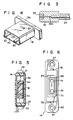
- Fig. 3 is a sectional view of a ferrule,
- Fig. 4 is a perspective view of a floating holder,
- Fig. 5 is a sectional view taken along line V-V of Fig. 1,
- Fig. 6 is a front view of the adaptor,
- Figs. 7A to 7C are partial sectional views showing the steps of connecting the plug to the adaptor, and
- Fig. 8 is a plan view of the optical connector in the state that the plug is connected to the adaptor; and
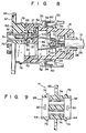
- Fig. 9 is a sectional view showing a modification of the adaptor.
- An embodiment of this invention will now be described in detail with reference to the accompanying drawings.
- As shown in Figs. 1 and 2, an optical connector is provided with
optical connector plug 12 attached to the end ofoptical fiber cable 10, andoptical connector adaptor 14 to which the plug is to be connected. -
Plug 12 hasplug body 16, in the form of thin box, fixed tocable 10, andfloating holder 18 so arranged within the plug body to allow it to float. Onplug body 16 are formedholder receiving space 20 which is open to the front end of the body and has a rectangular cross section, andfiber receiving space 22 which is open to the back end of the body and communicates withspace 20. An inner surface ofbody 16 which definesspace 20 is formed with regulatinggroove 21 which extendes throughout the entire periphery of the inner surface. Regulatinggroove 21, likespace 20, has a rectangular cross section. On the rear end ofplug body 16 is fixedoptical fiber cable 10.Cable 10 includestension wire 23 which is formed of φ1.2 mm steel wire, for instance, and embedded in polyethylene resin, two nylon jacketedfibers 24, andsheath 26 made of PVC (polyvinylchloride) coveringwire 23 andfibers 24. An end portion ofsheath 26 is fixed toplug body 16 by means ofbush 28, and is located at the rear end ofspace 22.Wire 23 andoptical fiber 24 extend frontward from the fixed end ofsheath 26, and the wire is fixed tobody 16 throughwire holder 30 located withinspace 22. Eachoptical fiber 24 extends into holderreceiving space 20, andferrule 32 is fixed to the extended end of eachfiber 24. As shown in Figs. 1 and 3,ferrule 32 is formed of stainless steel, for instance, into a substantially cylindrical shape with a high dimensional accuracy. Fiber 24 is forcibly inserted intoferrule 32 and extends to the end of the ferrule. In Fig. 3, reference numeral 24a represents a bare fiber offiber 24 formed of quartz and numeral 33 a ceramics tip with a capillary.Annular stopper 34 is provided on the outer periphery at the middle portion of eachferrule 32. - As shown in Figs. 1, 4 and 5,
floating holder 18 is formed into a rectangular cylindrical shape, and has a cross section which is similar to the cross section ofholder receiving space 20 and smaller than that ofspace 20. In addition,holder 18 hasrectangular flange 36 formed, as a regulating section, on the outer periphery at the rear end ofholder 18. Thisflange 36 has a cross section which is similar in shape to that of regulatinggroove 21 ofplug body 16 and smaller than that of the groove. Also,flange 36 is thinner than the width of regulatinggroove 21.Projections 37 for engagement are formed on both the upper and lower surfaces ofholder 18.Holder 18 is arranged in receivingspace 20 ofbody 16 withflange 36 being located within regulatinggroove 21. Sinceholder 18 andflange 36 have cross sections smaller than those ofspace 20 and regulatinggroove 21, respectively, the holder is so arranged withinspace 20 as to allow its free movement in x, y and z directions. - Within
holder 18 is formedpartition wall 38 which divides inside the holder intoadaptor fitting recess 40 which is open to the front end of the holder, and retainingelement fitting recess 42 which is open to the rear end of the holder, i.e., on the side offlange 36. A pair of through-holes 43 are formed inpartition wall 38 and extend along the axis ofholder 18. The distal end portions offerrules 32 are inserted into through-holes 43 to be slidable along the respective axis, and project frontward fromholder 18. Retainingelement 46 formed with a pair of fiber insertion holes 44 is fitted intorecess 42. Into eachinsertion hole 44 are loosely inserted the proximal end portion ofcorresponding ferrule 32 andoptical fiber 24.Coil spring 48 is arranged around the proximal end portion of eachferrule 32, and one end of the spring is in contact withstopper 34 of the ferrule and the other end is in contact with retainingelement 46. Byspring 48,ferrule 32 is thus urged frontward ofholder 18 with force of about 800 to 1200 g, andstopper 34 is held in contact withpartition wall 38. As in the above manner, eachferrule 32 is pressed byspring 48, and is allowed to move backward along the axis offerrule 32 untilspring 48 completely contracts. Eachferrule 32 is prevented from rotating by an anti-rotation pin which is not shown. Whileholder 18 is held withinplug body 16, eachfiber 24 is loose betweenferrule 32 and the end ofcable sheath 26. - Also, as shown in Figs. 1 and 2, on
plug body 16 is providedlock mechanism 50 for lockingplug 12 andadaption 14 in a connected state whenplug 12 is connected toadaptor 14.Lock mechanism 50 has a pair of lock levers 52 which are rotatably supported on both sides ofbody 16, respectively. More detailed, upper andlower support peices 54 extend from each said ofbody 16, and supportingshaft 56 is rotatably provided between the support pieces.Lock lever 52 is rotatably supported onshaft 56.Distal end portion 52a of eachlock lever 52 projects frontward fromplug body 16.End portion 52a is formed withsquare hole 58 as an engaging section.Torsion spring 60 is arranged around eachshaft 56, and locklevers 52 are urged bysprings 60 towardbody 16, that is, urged in that direction in whichend portions 52a oflevers 52 come close to each other. - As shown in Figs. 1, 2 and 6,
adaptor 14 is provided withbody 62 of a rectangular pillar shape. On the front ofbody 62 is provided first connectingportion 63 to which plug 12 is to be connected. On the back ofbody 62 is provided second connectingportion 65 to which another optical connector plug (not shown) is to be connected. First connectingportion 63 has rectangularfitting frame 64 projecting from the front ofbody 62. On the end edge at the back side ofbody 62 is formedflange 66 in which are formed a pair of fixing holes 67. - The inner surface of
frame 64 definesholder fitting recess 68 into which floatingholder 18 ofplug 12 is fitted.Recess 68 has a cross section of the same shape as that ofholder 18 and slightly larger than the latter. The inner surface offrame 64 serves asguide surface 69 for guiding insertion ofholder 18 into fittingrecess 68.Frame 64 has a profile which is similar to the cross section ofholder receiving space 20 ofplug body 16 to allow its insertion intospace 20. In other words,frame 64 is so formed that plugbody 16 can be fitted onframe 64, and the frame itself formsfitting section 70. The outer surface offrame 64 forms guide surface 71 for guiding the fitting ofplug body 16 onto the frame. In the upper and lower walls offrame 64 are formed engagingholes 80 to which engagingprojections 37 of floatingholder 18 are fitted, respectively. On the bottom ofrecess 68 is formedprojection 72 which is to be fitted to recess 40 of floatingholder 18. A pair of parallel ferrule insertion holes 74 are formed inbody 62. Eachinsertion hole 74 has an end open toprojection 72, i.e., the bottom of fittingrecess 68, and the other end open to the back ofbody 62. A pair of annular threadedportions 76 constituting second connectingportion 65 are formed on the back ofbody 62. Each threadedportion 76 communicates with the other end of thecorresponding insertion hole 74. A single core type optical connector plug (not shown) is to be connected to each threadedportion 76. On each side ofbody 64 is formedprojection 78 for engaging withsquare hole 58 ofcorresponding lock lever 52 whenplug 12 is connected toadaptor 14. Eachinsertion hole 74 is machined with high accuracy in its inner diameter so thatferrule 32 inserted into it does not move inside it. - The connection of the optical connector having the above structure is performed in the following manner.
- As shown in Fig. 7A,
first plug 12 is inserted toadaptor 14 while the end of floatingholder 18 is fitted toholder fitting recess 68 ofadaptor 14. When making insertion, the rear surface offlange 36 ofholder 18 comes into contact withrear surface 21a of regulatinggroove 21 onplug body 16, and the holder is pushed by thisrear surface 21a. In accordance with the insertion ofplug 12,frame 64 ofadaptor 14 goes intoholder receiving space 20 ofplug body 16, and at the same time,projection 72 onadaptor 14 goes into fittingrecess 40 formed on the end ofholder 18. The distal end of eachlock lever 52 onplug 12 comes into contact with correspondingprojection 78 onadaptor 14, and the levers are rotated in the direction away from each other. Figs. 7B and 8 show the condition immediately afterplug 12 is connected toadaptor 14. Whenplug 12 is completely inserted,flange 36 ofholder 18 comes into contact with the end offitting frame 64, andprojection 72 onadaptor 14 is fitted inrecess 40 of the holder. As a result,ferrules 32 are inserted into ferrule insertion holes 74 ofadaptor 14, respectively. With this condition, moreover, engagingprojections 37 onholder 18 engage with engagingholes 80 ofengagement frame 64, respectively, thereby holding the holder within the frame. Simultaneously,projections 78 onadaptor 14 are inserted intosquare holes 58 of lock levers 52, respectively, thereby lockingplug body 16 toadaptor 14. In this state gap a is formed between the edge ofsquare hole 58 andprojection 78, and gap b larger than gap a is formed between the front surface offlange 36 ofholder 18 and the front surface of regulatinggroove 21 which faces the former. - Fig. 7C shows the condition where an external force along direction z is applied on
plug body 16 oroptical fiber cable 10 to pull it backward. In this case, plugbody 16 moves until the edge ofsquare hole 58 oflock lever 52 comes into contact withprojection 78 onadaptor 14, and its further movement is prevented by the lock levers. In this state, gap c with the same width as gap a is defined between the rear surface offlange 36 andrear surface 21a of regulatinggroove 21. Between the front surface offlange 36 and the front surface ofgroove 21, gap d is left, which is as large as gap b minus moving distance offlange assembly 16. Thus, even ifplug body 16 moves as mentioned above, the plug body does not contact withflange 36, i.e., floatingholder 18, and thus external force applied on the plug body is not transferred to the holder. Accordingly ferrules 32 is not influenced by external force.Sheath 26 ofoptical fiber cable 10 is fixed to plugbody 16 by means ofbush 28, andwire 23 embedded in the cable is fixed tobody 16. An external force applied tocable 10, therefore, is transferred to plugbody 16 viabush 28 andwire 23, but not to floatingholder 18 viaoptical fiber 24. - Even if
plug body 16 moves in the directions of x and y,holder 18 is not moved. As it is clear from Fig. 5, gap e is defined between the outer surface offlange 36 ofholder 18 and the inner surface of regulatinggroove 21 ofplug body 16. This gap e prevents the movement ofplug body 16 in the directions of x and y from being transferred toholder 18. - An impact test was conducted, applying an imapct of 100G for 5 ms on the optical connector in the x-direction, y-direction, and z-direction, while keeping
plug 12 coupled toadaptor 14, and also maintaining single-fiber connector plugs (not shown) connected to threadedportions 76. The test showed that no interruption of transmission of optical signals, which amount to more than 0.03 dB and are longer than 60 msec., took place. - In the optical connector described above,
holder 18 holding the ferrules, so to speak, floats, not being fixed to plugbody 16, and can freely move. Hence, in the state thatholder 18 is fitted to frame 64 and locked thereto by the half lock mechanism, even if an external force, such as an impact, is applied to plugbody 16 or the optical fiber, it does not act on the ferrules. No interruptions of transmission of optical signals occur. The optical connector can, therefore, ensure a reliable optical signal transmission. It is not only easy to operate, but also mechanically strong against vibration, impact, etc., and can therefore provide a very reliable optical signal transmission. - The invention can apply to connectors for connecting one optical fiber to another, or more than two optical fibers to the same number of optical fibers, instead of connecting only two optical fiber to other two as practiced in the embodiment. Further, the holder can have holes (i.e., engaging section), and the adaptor can have projections (i.e., stopping section). In this case, too, the same advantages can be obtained as in the embodiment wherein the holder has projections and the adaptor has holes. Further, in order to attain the same advantages, the holder can be provided with magnets, and the adaptor can be provided with magnetic parts, or vice versa.
- Moreover, it suffices to replace the regulating portion of the floating holder with a projection, and the regulating recess of the plug body with hole, in order that the holder is prevented from dropped from the plug body and can freely move.
- Still further, the lock mechanism for locking the plug body to the adaptor can be comprised of projections provided on the plug body, and lock levers provided on the adaptor. Alternatively, the mechanism can be so constructed that it can be operated by a single touch.
- In the embodiment, the adaptor has the first connecting section to which a two-fiber plug can be coupled, and the second connecting section to which a single-fiber plug can be coupled. Instead, as is shown in Fig. 9, the second connecting section can have the same structure as the first connecting section, so that a two-fiber plug can be connected to it.
- Furthermore, an alignment sleeve having a slit, into which a ferrule can be inserted, can be provided in the hole of the adaptor.
Claims (13)
- An optical connector for connecting optical fibers to optical elements, comprising:
an adaptor (14) for receiving optical elements, including a plug connecting section (63);
a connector plug (12) to be connected to the plug connecting section (63) of the adaptor (14);
a lock mechanism (50) for locking the plug (12) to the adaptor (14) when the plug (12) is connected to the adaptor (14);
said plug (12) including a plug body (16) to be fitted to the plug connecting section (63) of the adaptor, said plug body (16) being locked to the plug connecting section (63) by said lock mechanism (50) when the plug body (16) is fitted to the plug connecting section (63); and
a ferrule (32) attached to an end of an optical fiber (24) and supported by the plug (12);
characterized in that
said adaptor (14) has engagement means (80);
said plug connecting section (63) includes a plug body fitting portion (70) and a holder fitting portion (68);
said plug body (16) is to be fitted and adapted to be locked to said plug body fitting portion (70);
said plug (12) includes a floating holder (18) to be fitted to said holder fitting portion (68), the floating holder (18) being arranged in the plug body (16) to be movable in any direction in relation to the plug body (16) and also having engaging means (37) for engaging with said engagement means (80) of said adaptor to lock the floating holder (18) to said holder fitting portion (68) when said floating holder (18) is fitted to said holder fitting portion (68); and
said ferrule (32) is supported by said floating holder (18). - An optical connector according to claim 1, characterized in that said plug body (16) has a holder receiving space (20) which is open to the outer surface of the plug body, the floating holder (18) is arranged in the holder receiving space with a certain gap, and the plug (12) includes regulating means for preventing the holder from slipping out of the holder receiving space.
- An optical connector according to claim 2, characterized in that said adaptor (14) includes a body (62) and a fitting element (64) projecting from the body, the fitting element having an outer surface defining the plug body fitting portion (70) and an inner surface defining the holder fitting portion (68), and said fitting element being formed in a shape which can be inserted into the holder receiving space (20).
- An optical connector according to claim 3, characterized in that said fitting element (64) is formed in a tubular shape, the outer surface of the fitting element having a profile similar to that of a cross section of the holder receiving space (20), and the inner surface of the fitting element having a profile similar to that of a cross section of the floating holder (18).
- An optical connector according to claim 3, characterized in that said engagement holes (80) is formed on the inner surface on the fitting element, and the engaging section (37) is formed on the outer surface of the floating holder (18).
- An optical connector according to claim 2, characterized in that said regulating means includes a regulating recess (21) formed in the plug body (16) to open to the holder receiving space (20), and a regulating portion (36) projecting from the floating holder (18) and located in the regulating recess with a gap.
- An optical connector according to claim 6, characterized in that said ferrule (32) has an axis and a distal end portion projecting from the floating holder (18), and the floating holder and regulating portion (36) are arranged in the holder receiving space (20) and regulating recess (21), respectively, to be movable in a direction perpendicular to the ferrule axis and in the axial direction of the ferrule.
- An optical connector according to claim 7, characterized in that said ferrule (32) is arranged in the floating holder (18) to be movable along the axis of the ferrule and having a stopper (34) for preventing the ferrule from slipping out of the holder, and the floating holder includes an urging element (48) for urging the ferrule in the direction in which the ferrule projects from the holder.
- An optical connector according to claim 7, characterized in that said adaptor (14) is provided with an insertion hole (74) to which the distal end portion of the ferrule (32) is inserted when the plug (12) is connected to the adaptor.
- An optical connector according to claim 1, characterized in that said lock mechanism (50) includes a projection (78) formed on the adaptor (14), and a lock lever (52) mounted on the plug body (16) and having a hole (58) which engages with the projection when the plug (12) is connected to the adaptor.
- An optical connector according to claim 1, characterized in that said adaptor includes a second connecting section to which another optical connector plug is to be connected, the second connecting section opposing to the first connecting section.
- An optical connector according to claim 1, characterized in that
an optical fiber cable (10) is provided having said optical fiber (24) and a coating (26) covering it, the coating having a distal end and the optical fiber (24) having an extended portion extending from the distal end of the coating;
said ferrule (32) is attached to said extended portion of said optical fiber (24);
said optical fiber cable (10) has a tension wire (23) embedded in the coating (26) and having an extended portion extending from the distal end of said coating (26);and
said coating (26) and said extended portion of said tension wire (23) are fixed to said plug body (16). - An optical connector according to claim 12, characterized in that said extended portion of the optical fiber (24) is loose between an end of the coating (26) of the optical fiber cable (10) and the ferrule (32).
Applications Claiming Priority (2)
| Application Number | Priority Date | Filing Date | Title |
|---|---|---|---|
| JP60289151A JPH077139B2 (en) | 1985-12-24 | 1985-12-24 | Floating holder type optical connector |
| JP289151/85 | 1985-12-24 |
Publications (3)
| Publication Number | Publication Date |
|---|---|
| EP0228063A2 EP0228063A2 (en) | 1987-07-08 |
| EP0228063A3 EP0228063A3 (en) | 1989-08-02 |
| EP0228063B1 true EP0228063B1 (en) | 1993-09-29 |
Family
ID=17739420
Family Applications (1)
| Application Number | Title | Priority Date | Filing Date |
|---|---|---|---|
| EP86117858A Expired - Lifetime EP0228063B1 (en) | 1985-12-24 | 1986-12-22 | Optical connector |
Country Status (5)
| Country | Link |
|---|---|
| US (1) | US4759599A (en) |
| EP (1) | EP0228063B1 (en) |
| JP (1) | JPH077139B2 (en) |
| KR (1) | KR900005739B1 (en) |
| DE (1) | DE3689113T2 (en) |
Cited By (13)
| Publication number | Priority date | Publication date | Assignee | Title |
|---|---|---|---|---|
| EP0330231A3 (en) * | 1988-02-26 | 1990-08-22 | Nippon Telegraph And Telephone Corporation | Plug-in connector |
| EP0398613A3 (en) * | 1989-05-17 | 1991-02-27 | Yamaichi Electric Mfg. Co. Ltd.. | Cable fixing element for a connector of a multicore type optical fiber cable |
| FR2665581A1 (en) * | 1990-07-16 | 1992-02-07 | Puritan Bennett Corp | ELECTRICAL-OPTICAL HYBRID CONNECTOR. |
| EP0430107A3 (en) * | 1989-11-24 | 1992-09-23 | Nippon Telegraph And Telephone Corporation | Optical connector |
| US5242315A (en) * | 1992-05-21 | 1993-09-07 | Puritan-Bennett Corporation | Electrical-optical hybrid connector plug |
| US5436993A (en) * | 1993-01-21 | 1995-07-25 | Sirti S.P.A. | Multiple connector for multi-fibre optic ribbons |
| US5528711A (en) * | 1989-11-24 | 1996-06-18 | Nippon Telegraph And Telephone Corp. | Optical connector for connecting a plurality of optical plugs to a connector housing |
| US5537501A (en) * | 1989-11-24 | 1996-07-16 | Nippon Telegraph And Telephone Corporation | Optical connector |
| US5647043A (en) * | 1995-10-12 | 1997-07-08 | Lucent Technologies, Inc. | Unipartite jack receptacle |
| US5673346A (en) * | 1989-11-24 | 1997-09-30 | Nippon Telegraph And Telephone Corporation | Optical jack for plug-jack optical connector |
| WO2003071205A1 (en) | 2002-02-25 | 2003-08-28 | BSH Bosch und Siemens Hausgeräte GmbH | Inner part for a refrigerating device |
| WO2004015337A1 (en) | 2002-08-05 | 2004-02-19 | BSH Bosch und Siemens Hausgeräte GmbH | Refrigerating appliance comprising water-bearing fittings |
| DE202004021743U1 (en) | 2003-08-11 | 2010-08-19 | BSH Bosch und Siemens Hausgeräte GmbH | Refrigerating appliance with water-bearing internals |
Families Citing this family (36)
| Publication number | Priority date | Publication date | Assignee | Title |
|---|---|---|---|---|
| US5166995A (en) * | 1984-06-08 | 1992-11-24 | Amp Incorporated | Polarized connector |
| JPH0522887Y2 (en) * | 1987-08-31 | 1993-06-11 | ||
| US4826277A (en) * | 1987-10-30 | 1989-05-02 | Amp Incorporated | Transition of a multiple fiber cable to single fiber cable |
| US5011246A (en) * | 1989-05-19 | 1991-04-30 | E. I. Du Pont De Nemours And Company | Housing for an opto-electronic device |
| US4978194A (en) * | 1989-08-28 | 1990-12-18 | Raynet Corporation | Stepped cable block |
| US5117479A (en) * | 1990-11-02 | 1992-05-26 | Amp Incorporated | Clamp for split cable of multiple optical fibers |
| SE500190C2 (en) * | 1991-01-30 | 1994-05-02 | Bernd Stanitz | Multichannel connection device |
| US5109453A (en) * | 1991-02-25 | 1992-04-28 | Amp Incorporated | Optical fiber connector with latching beam mechanism |
| US5133032A (en) * | 1991-04-17 | 1992-07-21 | Salter James R | Optical fiber connector |
| US5140663A (en) * | 1991-04-17 | 1992-08-18 | Amp Incorporated | Latching beam mechanism having plug stops for optical connector |
| US5159654A (en) * | 1991-10-25 | 1992-10-27 | Optex Biomedical, Inc. | Multi-channel optical fiber connector |
| US5315679A (en) * | 1992-04-27 | 1994-05-24 | International Business Machines Corporation | Optical fibers duplex connector assembly |
| JP2780640B2 (en) * | 1994-05-25 | 1998-07-30 | 住友電装株式会社 | Optical fiber cable connector |
| US5553180A (en) * | 1995-01-17 | 1996-09-03 | Molex Incorporated | Adapter assembly for fiber optic connectors |
| US5608828A (en) * | 1995-09-12 | 1997-03-04 | Itt Corporation | Fiber optic connector apparatus |
| AU716587B2 (en) * | 1995-10-31 | 2000-03-02 | Indigo Medical, Incorporated | Fiber optic radiation transmission system, connector system for an optical fiber, and methods of using same |
| NL1002955C2 (en) * | 1996-04-26 | 1997-10-28 | Framatome Connectors Belgium | Multifiber connector plug. |
| JP3335277B2 (en) * | 1996-05-07 | 2002-10-15 | 株式会社エンプラス | Wire holder and optical fiber connector |
| US6007256A (en) * | 1996-09-24 | 1999-12-28 | Sumitomo Wiring Systems, Ltd. | Optical connector that reduces the number of components used, that facilitates assembly, and that prevents spontaneous disassembly, and structure for attaching a boot to an optical connector |
| US5926596A (en) * | 1998-01-28 | 1999-07-20 | The Whitaker Corporation | Overmolded alignment ferrule |
| US6224268B1 (en) * | 1998-04-23 | 2001-05-01 | The Whitaker Corporation | Plug housing with attached cantilevered latch for a fiber optic connector |
| US6454464B1 (en) | 1998-12-28 | 2002-09-24 | Computer Crafts, Inc. | Fiber optic connectors and transceiver test devices |
| US6464408B1 (en) | 1998-12-28 | 2002-10-15 | Computer Crafts, Inc. | Fiber optic connectors |
| EP1072918B1 (en) * | 1999-07-26 | 2005-03-30 | Diamond SA | Connector part for optical connection |
| DE50009898D1 (en) * | 1999-07-26 | 2005-05-04 | Diamond Sa | Plug part for an optical connector |
| EP1072920A1 (en) * | 1999-07-26 | 2001-01-31 | Diamond SA | Connector plug for an optical connection |
| US6511230B1 (en) | 2000-02-04 | 2003-01-28 | Panduit Corp. | Fiber optic connection system |
| AU2002220718A1 (en) * | 2000-11-21 | 2002-06-03 | Euromicron Werkzeuge Gmbh | Connector for optical waveguides comprising a connector housing |
| US6485189B1 (en) | 2001-05-09 | 2002-11-26 | Stratos Lightwave, Inc. | High density multiple fiber optic connector |
| JP2002341182A (en) * | 2001-05-14 | 2002-11-27 | Auto Network Gijutsu Kenkyusho:Kk | Optical connector |
| US6734435B2 (en) * | 2001-05-29 | 2004-05-11 | Rae Systems, Inc. | Photo-ionization detector and method for continuous operation and real-time self-cleaning |
| RU2460100C2 (en) * | 2006-11-13 | 2012-08-27 | Сумитомо Электрик Индастриз, Лтд. | Holder, fusion splicing apparatus and method of assembling optical connector |
| US20110158588A1 (en) * | 2009-12-25 | 2011-06-30 | Hon Hai Precision Industry Co., Ltd. | Cable assembly having floatable optical module |
| JP2012220731A (en) * | 2011-04-08 | 2012-11-12 | Yazaki Corp | Optical connector |
| CN105122109B (en) | 2013-04-15 | 2018-04-03 | 胡贝尔舒纳公司 | Optical connector assembly |
| PL4237889T3 (en) * | 2020-10-30 | 2026-01-26 | Corning Research & Development Corporation | FEMALE FIBER OPTIC CONNECTORS WITH LOCKING ARM WITH ROCKING MECHANISM |
Family Cites Families (12)
| Publication number | Priority date | Publication date | Assignee | Title |
|---|---|---|---|---|
| US3596018A (en) * | 1969-06-25 | 1971-07-27 | Howard Gross | Electrical connection device for vehicles |
| US3840839A (en) * | 1973-02-01 | 1974-10-08 | Akzona Inc | Asymmetrical electrical connector with aligning means |
| DE2933790C2 (en) * | 1979-08-21 | 1982-05-27 | Standard Elektrik Lorenz Ag, 7000 Stuttgart | Detachable connection device for light guides |
| FR2479484A1 (en) * | 1980-03-26 | 1981-10-02 | Perena | Optical fibre connector - has tubular body with two truncated conical sleeves receiving connector members which are axially displaceable within body |
| JPS5878111A (en) * | 1981-11-04 | 1983-05-11 | Sumitomo Electric Ind Ltd | Double core connector |
| JPS6037529Y2 (en) * | 1981-12-28 | 1985-11-08 | 日本電信電話株式会社 | Plug-in optical connector |
| US4681398A (en) * | 1983-01-03 | 1987-07-21 | Switchcraft, Inc. | Fiber optic connector and method of assembly |
| JPS59140410A (en) * | 1983-01-31 | 1984-08-11 | Fujitsu Ltd | Optical connector coupling structure |
| GB2149589B (en) * | 1983-11-08 | 1988-06-02 | Davis & Son John | A connector for releasable connection of a first to a second apparatus |
| JPS60152109U (en) * | 1984-03-19 | 1985-10-09 | デユポン ジヤパン リミテツド | optical data link |
| AU577099B2 (en) * | 1984-03-19 | 1988-09-15 | E.I. Du Pont De Nemours And Company | Receptacle, plug and optical connector |
| US4682848A (en) * | 1984-10-03 | 1987-07-28 | Lockheed Corporation | Underwater-mateable optical fiber connector |
-
1985
- 1985-12-24 JP JP60289151A patent/JPH077139B2/en not_active Expired - Fee Related
-
1986
- 1986-12-15 KR KR1019860010728A patent/KR900005739B1/en not_active Expired
- 1986-12-19 US US06/943,769 patent/US4759599A/en not_active Expired - Lifetime
- 1986-12-22 EP EP86117858A patent/EP0228063B1/en not_active Expired - Lifetime
- 1986-12-22 DE DE86117858T patent/DE3689113T2/en not_active Expired - Lifetime
Cited By (16)
| Publication number | Priority date | Publication date | Assignee | Title |
|---|---|---|---|---|
| EP0330231A3 (en) * | 1988-02-26 | 1990-08-22 | Nippon Telegraph And Telephone Corporation | Plug-in connector |
| EP0398613A3 (en) * | 1989-05-17 | 1991-02-27 | Yamaichi Electric Mfg. Co. Ltd.. | Cable fixing element for a connector of a multicore type optical fiber cable |
| US5528711A (en) * | 1989-11-24 | 1996-06-18 | Nippon Telegraph And Telephone Corp. | Optical connector for connecting a plurality of optical plugs to a connector housing |
| US5537501A (en) * | 1989-11-24 | 1996-07-16 | Nippon Telegraph And Telephone Corporation | Optical connector |
| EP0430107A3 (en) * | 1989-11-24 | 1992-09-23 | Nippon Telegraph And Telephone Corporation | Optical connector |
| US5673346A (en) * | 1989-11-24 | 1997-09-30 | Nippon Telegraph And Telephone Corporation | Optical jack for plug-jack optical connector |
| US5404416A (en) * | 1989-11-24 | 1995-04-04 | Nippon Telegraph & Telephone Corporation | Optical connector plug |
| FR2665581A1 (en) * | 1990-07-16 | 1992-02-07 | Puritan Bennett Corp | ELECTRICAL-OPTICAL HYBRID CONNECTOR. |
| EP0467631A3 (en) * | 1990-07-16 | 1992-04-01 | Puritan-Bennett Corporation | Electrical-optical hybrid connector |
| US5242315A (en) * | 1992-05-21 | 1993-09-07 | Puritan-Bennett Corporation | Electrical-optical hybrid connector plug |
| US5436993A (en) * | 1993-01-21 | 1995-07-25 | Sirti S.P.A. | Multiple connector for multi-fibre optic ribbons |
| US5647043A (en) * | 1995-10-12 | 1997-07-08 | Lucent Technologies, Inc. | Unipartite jack receptacle |
| WO2003071205A1 (en) | 2002-02-25 | 2003-08-28 | BSH Bosch und Siemens Hausgeräte GmbH | Inner part for a refrigerating device |
| US10465973B2 (en) | 2002-02-25 | 2019-11-05 | BSH Hausgeräte GmbH | Inner part for a refrigerating device |
| WO2004015337A1 (en) | 2002-08-05 | 2004-02-19 | BSH Bosch und Siemens Hausgeräte GmbH | Refrigerating appliance comprising water-bearing fittings |
| DE202004021743U1 (en) | 2003-08-11 | 2010-08-19 | BSH Bosch und Siemens Hausgeräte GmbH | Refrigerating appliance with water-bearing internals |
Also Published As
| Publication number | Publication date |
|---|---|
| KR870006421A (en) | 1987-07-11 |
| JPS62148907A (en) | 1987-07-02 |
| EP0228063A2 (en) | 1987-07-08 |
| EP0228063A3 (en) | 1989-08-02 |
| DE3689113D1 (en) | 1993-11-04 |
| JPH077139B2 (en) | 1995-01-30 |
| KR900005739B1 (en) | 1990-08-09 |
| US4759599A (en) | 1988-07-26 |
| DE3689113T2 (en) | 1994-03-31 |
Similar Documents
| Publication | Publication Date | Title |
|---|---|---|
| US4759599A (en) | Optical connector | |
| US6179482B1 (en) | Optical connector and housing for optical connector | |
| AU685710B2 (en) | Optical fiber connector plug and optical fiber connector | |
| US11054586B2 (en) | Optical connector and optical connection structure | |
| US11940655B2 (en) | Optical connector and optical connection structure | |
| EP3474052B1 (en) | Optical connector and optical connection structure | |
| KR920010946B1 (en) | Releasable connector for optical fibers | |
| KR100283420B1 (en) | Optical connector | |
| GB2045454A (en) | Connecting optic fibres | |
| JP2024075729A5 (en) | ||
| US6394662B1 (en) | Optical fibre connector | |
| US4818061A (en) | Ferrule for connecting optical fibers and optical connector using it | |
| US9658405B2 (en) | Connector for collimated optical fiber | |
| JP7786395B2 (en) | Optical connector and optical connection structure | |
| JP4255803B2 (en) | Optical connector | |
| JPS6261923B2 (en) | ||
| JPS6128909A (en) | Optical connector | |
| JPH04174407A (en) | Optical connector | |
| JP2519233B2 (en) | Multi-fiber batch switch for optical fiber | |
| JPH06265757A (en) | Connector | |
| JPS63151910A (en) | Optical connector | |
| JP2501499Y2 (en) | Simple connector for optical fiber | |
| JPH0435845Y2 (en) | ||
| JPS60213914A (en) | Optical fiber connector | |
| JPH11326702A (en) | Optical connector |
Legal Events
| Date | Code | Title | Description |
|---|---|---|---|
| PUAI | Public reference made under article 153(3) epc to a published international application that has entered the european phase |
Free format text: ORIGINAL CODE: 0009012 |
|
| 17P | Request for examination filed |
Effective date: 19870119 |
|
| AK | Designated contracting states |
Kind code of ref document: A2 Designated state(s): DE FR GB |
|
| PUAL | Search report despatched |
Free format text: ORIGINAL CODE: 0009013 |
|
| AK | Designated contracting states |
Kind code of ref document: A3 Designated state(s): DE FR GB |
|
| 17Q | First examination report despatched |
Effective date: 19920309 |
|
| GRAA | (expected) grant |
Free format text: ORIGINAL CODE: 0009210 |
|
| AK | Designated contracting states |
Kind code of ref document: B1 Designated state(s): DE FR GB |
|
| REF | Corresponds to: |
Ref document number: 3689113 Country of ref document: DE Date of ref document: 19931104 |
|
| ET | Fr: translation filed | ||
| PLBE | No opposition filed within time limit |
Free format text: ORIGINAL CODE: 0009261 |
|
| STAA | Information on the status of an ep patent application or granted ep patent |
Free format text: STATUS: NO OPPOSITION FILED WITHIN TIME LIMIT |
|
| 26N | No opposition filed | ||
| REG | Reference to a national code |
Ref country code: GB Ref legal event code: IF02 |
|
| PGFP | Annual fee paid to national office [announced via postgrant information from national office to epo] |
Ref country code: FR Payment date: 20051208 Year of fee payment: 20 |
|
| PGFP | Annual fee paid to national office [announced via postgrant information from national office to epo] |
Ref country code: DE Payment date: 20051215 Year of fee payment: 20 |
|
| PGFP | Annual fee paid to national office [announced via postgrant information from national office to epo] |
Ref country code: GB Payment date: 20051221 Year of fee payment: 20 |
|
| PG25 | Lapsed in a contracting state [announced via postgrant information from national office to epo] |
Ref country code: GB Free format text: LAPSE BECAUSE OF EXPIRATION OF PROTECTION Effective date: 20061221 |
|
| REG | Reference to a national code |
Ref country code: GB Ref legal event code: PE20 |