EP0226761B1 - Release and alignment mechanism for jet-propelled projectiles - Google Patents
Release and alignment mechanism for jet-propelled projectiles Download PDFInfo
- Publication number
- EP0226761B1 EP0226761B1 EP86115007A EP86115007A EP0226761B1 EP 0226761 B1 EP0226761 B1 EP 0226761B1 EP 86115007 A EP86115007 A EP 86115007A EP 86115007 A EP86115007 A EP 86115007A EP 0226761 B1 EP0226761 B1 EP 0226761B1
- Authority
- EP
- European Patent Office
- Prior art keywords
- missile
- nozzle
- separation
- receptacle
- support means
- Prior art date
- Legal status (The legal status is an assumption and is not a legal conclusion. Google has not performed a legal analysis and makes no representation as to the accuracy of the status listed.)
- Expired
Links
- 230000007246 mechanism Effects 0.000 title claims description 16
- 238000000926 separation method Methods 0.000 claims description 31
- 230000000295 complement effect Effects 0.000 claims description 6
- 230000013011 mating Effects 0.000 claims description 2
- 239000007789 gas Substances 0.000 description 6
- 238000010438 heat treatment Methods 0.000 description 2
- 239000003380 propellant Substances 0.000 description 2
- 230000000087 stabilizing effect Effects 0.000 description 2
- 235000015842 Hesperis Nutrition 0.000 description 1
- 235000012633 Iberis amara Nutrition 0.000 description 1
- 230000004913 activation Effects 0.000 description 1
- 229910045601 alloy Inorganic materials 0.000 description 1
- 239000000956 alloy Substances 0.000 description 1
- 238000005219 brazing Methods 0.000 description 1
- 230000000694 effects Effects 0.000 description 1
- 238000004519 manufacturing process Methods 0.000 description 1
- 239000000463 material Substances 0.000 description 1
- 229910052751 metal Inorganic materials 0.000 description 1
- 239000002184 metal Substances 0.000 description 1
- 230000001141 propulsive effect Effects 0.000 description 1
- 230000000452 restraining effect Effects 0.000 description 1
- 229910000679 solder Inorganic materials 0.000 description 1
- 238000009987 spinning Methods 0.000 description 1
Images

Classifications
-
- F—MECHANICAL ENGINEERING; LIGHTING; HEATING; WEAPONS; BLASTING
- F41—WEAPONS
- F41F—APPARATUS FOR LAUNCHING PROJECTILES OR MISSILES FROM BARRELS, e.g. CANNONS; LAUNCHERS FOR ROCKETS OR TORPEDOES; HARPOON GUNS
- F41F3/00—Rocket or torpedo launchers
- F41F3/04—Rocket or torpedo launchers for rockets
- F41F3/048—Means for imparting spin to the rocket before launching
-
- F—MECHANICAL ENGINEERING; LIGHTING; HEATING; WEAPONS; BLASTING
- F41—WEAPONS
- F41C—SMALLARMS, e.g. PISTOLS, RIFLES; ACCESSORIES THEREFOR
- F41C27/00—Accessories; Details or attachments not otherwise provided for
- F41C27/06—Adaptations of smallarms for firing grenades, e.g. rifle grenades, or for firing riot-control ammunition; Barrel attachments therefor
-
- F—MECHANICAL ENGINEERING; LIGHTING; HEATING; WEAPONS; BLASTING
- F41—WEAPONS
- F41F—APPARATUS FOR LAUNCHING PROJECTILES OR MISSILES FROM BARRELS, e.g. CANNONS; LAUNCHERS FOR ROCKETS OR TORPEDOES; HARPOON GUNS
- F41F3/00—Rocket or torpedo launchers
- F41F3/04—Rocket or torpedo launchers for rockets
- F41F3/052—Means for securing the rocket in the launching apparatus
Definitions
- This invention relates to a release mechanism for facilitating launching of a spin-stabilized spherical jet-propelled missile.
- the projectiles spins about an axis upwardly inclined relative to the intended straight line path of flight and aligned with the thrust axis of the propulsion jet of the missile.
- the missile is released following ignition or activation of the jet propellant within the missile.
- the propulsion is effected by the reaction of the exhaust jet of, for example, a rocket motor housed within the spherical missile shell.
- spherical spin-stabilized missiles are provided in conjunction with attachments secured to the front end of an assault weapon such as a rifle
- a release mechanism for facilitating launching of a spin-stabilized spherical jet-propelled missile comprising missile support means including rotary support means and means for supporting the rotary means for rotation about a spin axis, the rotary means including receptacle means, a nozzle means on the missile and extending between the missile and the missile support means for securing the missile to the missile support means, the nozzle means extending into and mating with the receptacle means, the spin axis being coaxial with the nozzle means, and separation means between the missile and the missile support means.
- the nozzle means is a multi-part structure of which a fore part is secured to the missile, an aft part extends into and mates with the receptacle means by being in screwthreaded engagement therewith, and the separation means is an intermediate part which secures the fore and aft parts together.
- the aforesaid generally disclosed release mechanism is characterised by the provision of outwardly tapered shoulder means on the receptacle forwardly of the separation means and engageable with complementarily tapered shoulder means on the nozzle means to ensure proper alignment of the missile with the spin axis during initial separation of the separation means.
- the advantage of the invention is that the missile will remain stabilized right up to the point of launch since the engaging complementary shoulder means on the receptacle and the nozzle means are positioned forwardly of the zone of separation and so continue to effect alignment of the missile with the spin axis even when separation is taking place.
- the shoulder means on the receptacle means may comprise a forwardly opening conical section generally concentric with the axis of the nozzle means and engageable with the complementary shoulder means on the nozzle means which is also conical.
- the separation means may comprise fusible joint means in the nozzle means.
- a fusible joint means would be arranged to thermally disintegrate when heated by high-temperature exhaust gases expelled by the missile thereby releasing the missile for launch. Difficulties can be experienced in coordinating the spinning and release of a spherical spin-stabilized missile. Release of the missile prior to attainment of adequate rotational speed can result in unstable flight. Delay of release after attainment of adequate rotational speed can result in loss of propulsive range. Release of the missile at the optimum time can be ensured by fashioning the fusible joint means to thereby degrade at precisely the time when the missile has attained adequate rotational speed.
- the projectile release mechanism of the aforesaid US-A-3 554 078 is also specifically designed to temporarily restrain and automatically release a spherical spin-stabilized missile during spin-up, but exhibits the stabilizing problem of the missile during initial separation previously enumerated. ⁇ :
- the release mechanism of our aforesaid US-A-4 395 836 also provides for proper alignment of the missile with the spin axis during initial separation of the separation means constituted by the fusible joint means. This is afforded by the receptacle means and the nozzle member having, forwardly of the fusible joint means, complementarily engageable, axially spaced concentric lands.
- a spherical spin-stabilized jet-propelled missile 10 is shown mounted to the front of a barrel 12 of an assault weapon such as a rifle, generally designated 14.
- the rifle shown is a standard M-16A1 military rifle.
- a missile support means generally designated 16, includes a front upper bracket portion, generally designated 18, and a rear upper latch portion, generally designated 20.
- the bracket portion 18 is positioned on the barrel 12 whereby part of the gas emanating from the barrel is channeled through a passageway 22 ( Figure 2) to a pneumatically actuated pin assembly 24 which is effective to strike a primer on the missile 10 to ignite the rocket propellant therein as is known in the art.
- the latch 20 simply is provided to lock the support means 16 onto the rifle barrel.
- the support means 16 also includes turbine support portions 26 and 27, and rotary support means, generally designated 28.
- the rotary support means 28 is disposed on an axis 34 upwardly inclined relative to an extended straight line path of flight 36 generally parallel to the axis of the rifle barrel 12.
- the axis 34 is the spin axis of the missile 10 : i. e., the motor thrust of the missile rocket motor.
- the axis 36 defines the line of flight of the missile and is the forward velocity component thereof.
- the rotary support means 28 includes a plurality of turbine nozzles 38. In assembly, the rotary support means 28 is rotatable within the turbine support portions 26 and 27 by bearing means 40 and 42, respectively.
- the rotary support means 28 forms an open-ended receptacle having a forward open end 44 and a rear open end 46.
- the receptacle is generally coaxial with the spin axis 34 ( Figure 2).
- a nozzle assembly, generally designated 48 includes a fore section 50 and an aft section 52 ( Figures 4-6) joined by an integral fusible joint means, generally designated 54.
- the fusible joint means 54 is similar to that shown in the aforementioned US-A-4 395 836 and is disposed for heating by high-temperature exhaust gases expelled by the missile 10 to release the missile from the support means 16 and particularly from the rotary support means 28. More particularly, a plurality of passages 56 extend through the nozzle assembly 48 for conducting the exhaust gas through the fusible joint means 54, through internal passages 58, and out through the turbine nozzles 38. The remainder of the gases from the rocket motor within the missile 10 pass axially through the fore section 50 of the nozzle assembly 48, through an internal passage 60 and out through the turbine nozzles 38.
- the fore and aft sections, 50 and 52 can move out of the front and rear open ends 44 and 46, respectively, of the open-ended receptacle defined by the rotary support means 28, on fusing and separation of the fusible joint means 54.
- Means is provided for retaining the nozzle assembly 48 in the receptacle defined by the rotary support means 28 and for permitting the fore 50 and aft 52 sections of the nozzle assembly to separate and move out of the front and rear ends of the receptacle on separation at the fusible joint means 54. More particularly, a forwardly facing shoulder portion 61 and a rearwardly facing shoulder portion 62 are provided on the rotary support means 28.
- the forwardly facing shoulder portion 61 comprises a forwardly opening conical section generally concentric with the axis of the nozzle assembly 48 and terminating forwardly at the open end 44 of the receptacle.
- the nozzle assembly 48 is provided with a complementary rearwardly facing shoulder portion 64 and a forwardly facing shoulder portion 66 for engaging the forwardly and rearwardly facing shoulder portions 61 and 62, respectively.
- the rearwardly facing shoulder portion 64 of the nozzle assembly 48 has a conical conformation complementary to the conical section 61 on the interior of the rotary support means 28.
- Biasing means is provided operatively associated with the nozzle assembly 48 and effective to maintain the conical shoulder portions 61, 64 in engagement until complete separation of the fusible joint means 54, thereby accommodating any thermal expansion of the nozzle assembly, particularly in the area of the fusible joint means.
- a ring-like flange 68 is slidably mounted on a flat, circular land portion 70 of the aft section 52 of the nozzle assembly 48. This ring defines the forwardly facing shoulder portion 66 which engages the rearwardly facing shoulder portion 62 to retain the nozzle assembly 48 in the receptacle defined by the rotary support means 28.
- a plurality of coil springs 72 are equally spaced about and concentric with the axis of the nozzle assembly 48.
- Each spring 72 is sandwiched between the ring flange 68 and a washer 74 seated forwardly of a head portion 76 of a bolt or shaft 78.
- the shafts 78 protrude through the ring flange 68 and are secured to the rear side of the aft section 52 of the nozzle assembly 48.
- the ring flange 68 is biased by the springs 72 against the rearwardly facing shoulder portion 62 of the rotary support means 28.
- the springs 72 are effective to bias the entire nozzle assembly 48 rearwardly of the open-ended receptacle defined by the rotary support means 28.
- the nozzle assembly 48 is preloaded by the springs 72 and the springs are effective to accommodate any thermal expansion by biasing the aft section 52 of the nozzle assembly rearwardly and constantly maintaining the conical section 64 of the nozzle assembly in proper aligned engagement until complete separation of the fusible joint means 54. It should be understood that the invention contemplates the use of a single spring or other equivalent biasing means for preloading the nozzle assembly 48.
Landscapes
- Engineering & Computer Science (AREA)
- General Engineering & Computer Science (AREA)
- Aiming, Guidance, Guns With A Light Source, Armor, Camouflage, And Targets (AREA)
- Physical Or Chemical Processes And Apparatus (AREA)
Description
- This invention relates to a release mechanism for facilitating launching of a spin-stabilized spherical jet-propelled missile.
- It has become increasingly important to eliminate the features associated with a ballistic trajectory ordinarily followed by rockets and like jet-propelled projectiles, by forming the projectiles as spherical spin-stabilized missiles. The spherical missile spins about an axis upwardly inclined relative to the intended straight line path of flight and aligned with the thrust axis of the propulsion jet of the missile. The missile is released following ignition or activation of the jet propellant within the missile. The propulsion is effected by the reaction of the exhaust jet of, for example, a rocket motor housed within the spherical missile shell. Often such spherical spin-stabilized missiles are provided in conjunction with attachments secured to the front end of an assault weapon such as a rifle
- In US-A-3 554 078 there is generally disclosed in accordance with the preamble of claim 1 a release mechanism for facilitating launching of a spin-stabilized spherical jet-propelled missile, comprising missile support means including rotary support means and means for supporting the rotary means for rotation about a spin axis, the rotary means including receptacle means, a nozzle means on the missile and extending between the missile and the missile support means for securing the missile to the missile support means, the nozzle means extending into and mating with the receptacle means, the spin axis being coaxial with the nozzle means, and separation means between the missile and the missile support means.
- More particularly, in the aforesaid release mechanism the nozzle means is a multi-part structure of which a fore part is secured to the missile, an aft part extends into and mates with the receptacle means by being in screwthreaded engagement therewith, and the separation means is an intermediate part which secures the fore and aft parts together.
- Spin-stabilized spherical jet-propelled missiles experience difficulties in remaining stabilized during attainment of the desired rotational speed. Ensuring proper alignment of the missile with its spin axis during initial separation of the separation means is particularly important for stabilizing purposes. With the release mechanism of the aforesaid US-A-3 554 078, it is only the aft part which, by virtue of its screwthreaded engagement with the receptacle means, can act to align the missile with its spin axis, and there is the problem that the aft part is rendered ineffective for alignment purposes when initial separation occurs at the forwardly located separation means, the missile with the partly separated aft part of the nozzle structure then being free to gyrate about the spin axis.
- In accordance with the invention as claimed, the aforesaid generally disclosed release mechanism is characterised by the provision of outwardly tapered shoulder means on the receptacle forwardly of the separation means and engageable with complementarily tapered shoulder means on the nozzle means to ensure proper alignment of the missile with the spin axis during initial separation of the separation means.
- The advantage of the invention is that the missile will remain stabilized right up to the point of launch since the engaging complementary shoulder means on the receptacle and the nozzle means are positioned forwardly of the zone of separation and so continue to effect alignment of the missile with the spin axis even when separation is taking place.
- The shoulder means on the receptacle means may comprise a forwardly opening conical section generally concentric with the axis of the nozzle means and engageable with the complementary shoulder means on the nozzle means which is also conical.
- The separation means may comprise fusible joint means in the nozzle means. Such a fusible joint means would be arranged to thermally disintegrate when heated by high-temperature exhaust gases expelled by the missile thereby releasing the missile for launch. Difficulties can be experienced in coordinating the spinning and release of a spherical spin-stabilized missile. Release of the missile prior to attainment of adequate rotational speed can result in unstable flight. Delay of release after attainment of adequate rotational speed can result in loss of propulsive range. Release of the missile at the optimum time can be ensured by fashioning the fusible joint means to thereby degrade at precisely the time when the missile has attained adequate rotational speed.
- Attempts have previously been made to provide means for temporarily restraining and automatically releasing a spin-stabilized jet-propelled spherical missile during spin-up. For instance, in US-A-3 245 350, a mechanical release is provided between a rifle barrel and a spin-stabilized spherical missile in order to selectively release the missile. However, precise automatic release is not afforded.
- The projectile release mechanism of the aforesaid US-A-3 554 078 is also specifically designed to temporarily restrain and automatically release a spherical spin-stabilized missile during spin-up, but exhibits the stabilizing problem of the missile during initial separation previously enumerated. `:
- Another proposal is disclosed in US-A-4 395 836 published on 2nd August 1983 and assigned to the present applicant. Herein, a one-piece nozzle member is provided having fusible joint means as an integral part thereof and constituted by a fusible wall portion of the one-piece nozzle member. Thereby, manufacture of the nozzle member is simplified as compared to the multi-part nozzle structure of the aforesaid US-A-3 554 078 with which the intermediate part constituting the separation means is of silver solder or brazing alloy and is fused to the fore and aft parts thereby to secure them together.
- The release mechanism of our aforesaid US-A-4 395 836 also provides for proper alignment of the missile with the spin axis during initial separation of the separation means constituted by the fusible joint means. This is afforded by the receptacle means and the nozzle member having, forwardly of the fusible joint means, complementarily engageable, axially spaced concentric lands.
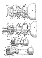
- In order that the invention may be well understood there will now be described an embodiment thereof, given by way of example, reference being had to the accompanying drawings, in which :
- Figure 1 is an elevational view of a spherical spin-stabilized missile mounted on the barrel of a rifle and incorporating a release mechanism embodying the present invention ;
- Figure 2 is a fragmented side elevational view, on an enlarged scale, of the spherical missile mounted on the front end of the rifle barrel ;
- Figure 3 is a fragmented side elevational view, partially in section, showing the interior components of the same release mechanism, prior to separation ;
- Figure 4 is a view similar to that of Figure 3, showing the components after fusing and separation of the fusible joint means ;
- Figure 5 is a perspective view of the nozzle assembly of the same release mechanism, prior to separation ; and
- Figure 6 is a perspective view similar to that of Figure 5, showing the nozzle assembly after fusing and separation of the fusible joint means.
- Referring first to Figure 1, a spherical spin-stabilized jet-propelled
missile 10 is shown mounted to the front of abarrel 12 of an assault weapon such as a rifle, generally designated 14. The rifle shown is a standard M-16A1 military rifle. - As shown in Figure 1 and in the enlarged view of figure 2, a missile support means, generally designated 16, includes a front upper bracket portion, generally designated 18, and a rear upper latch portion, generally designated 20. The
bracket portion 18 is positioned on thebarrel 12 whereby part of the gas emanating from the barrel is channeled through a passageway 22 (Figure 2) to a pneumatically actuatedpin assembly 24 which is effective to strike a primer on themissile 10 to ignite the rocket propellant therein as is known in the art. Thelatch 20 simply is provided to lock the support means 16 onto the rifle barrel. - The support means 16 also includes
turbine support portions axis 34 upwardly inclined relative to an extended straight line path offlight 36 generally parallel to the axis of therifle barrel 12. As is known in the art, theaxis 34 is the spin axis of the missile 10 : i. e., the motor thrust of the missile rocket motor. Theaxis 36 defines the line of flight of the missile and is the forward velocity component thereof. - Referring to figures 3-6, the rotary support means 28 includes a plurality of
turbine nozzles 38. In assembly, the rotary support means 28 is rotatable within theturbine support portions open end 44 and a rearopen end 46. Thus, the receptacle is generally coaxial with the spin axis 34 (Figure 2). - A nozzle assembly, generally designated 48, includes a
fore section 50 and an aft section 52 (Figures 4-6) joined by an integral fusible joint means, generally designated 54. The fusible joint means 54 is similar to that shown in the aforementioned US-A-4 395 836 and is disposed for heating by high-temperature exhaust gases expelled by themissile 10 to release the missile from the support means 16 and particularly from the rotary support means 28. More particularly, a plurality ofpassages 56 extend through thenozzle assembly 48 for conducting the exhaust gas through the fusible joint means 54, throughinternal passages 58, and out through theturbine nozzles 38. The remainder of the gases from the rocket motor within themissile 10 pass axially through thefore section 50 of thenozzle assembly 48, through aninternal passage 60 and out through theturbine nozzles 38. - Thus, it can be seen best in figures 4 and 6 that the fore and aft sections, 50 and 52, respectively, can move out of the front and rear
open ends - Means is provided for retaining the
nozzle assembly 48 in the receptacle defined by the rotary support means 28 and for permitting thefore 50 andaft 52 sections of the nozzle assembly to separate and move out of the front and rear ends of the receptacle on separation at the fusible joint means 54. More particularly, a forwardly facingshoulder portion 61 and a rearwardly facingshoulder portion 62 are provided on the rotary support means 28. The forwardly facingshoulder portion 61 comprises a forwardly opening conical section generally concentric with the axis of thenozzle assembly 48 and terminating forwardly at theopen end 44 of the receptacle. Thenozzle assembly 48 is provided with a complementary rearwardly facingshoulder portion 64 and a forwardly facingshoulder portion 66 for engaging the forwardly and rearwardly facingshoulder portions shoulder portion 64 of thenozzle assembly 48 has a conical conformation complementary to theconical section 61 on the interior of the rotary support means 28. These complementarily engageable conical sections greatly facilitate proper alignment of themissile 10 with thespin axis 34 during initial separation of thenozzle assembly 48 at the fusible joint means 54 because of its precise alignment prior to separation. - Biasing means is provided operatively associated with the
nozzle assembly 48 and effective to maintain theconical shoulder portions like flange 68 is slidably mounted on a flat,circular land portion 70 of theaft section 52 of thenozzle assembly 48. This ring defines the forwardly facingshoulder portion 66 which engages the rearwardly facingshoulder portion 62 to retain thenozzle assembly 48 in the receptacle defined by the rotary support means 28. A plurality ofcoil springs 72 are equally spaced about and concentric with the axis of thenozzle assembly 48. This ensures uniform pressure on thering flange 68. Eachspring 72 is sandwiched between thering flange 68 and awasher 74 seated forwardly of ahead portion 76 of a bolt orshaft 78. Theshafts 78 protrude through thering flange 68 and are secured to the rear side of theaft section 52 of thenozzle assembly 48. Thus, it can be seen that thering flange 68 is biased by thesprings 72 against the rearwardly facingshoulder portion 62 of the rotary support means 28. With thering flange 68 so seated, thesprings 72 are effective to bias theentire nozzle assembly 48 rearwardly of the open-ended receptacle defined by the rotary support means 28. This maintains theconical shoulder portion 64 on thefore section 50 of thenozzle assembly 48 seated on the complementaryconical shourder portion 61 on the interior of the rotary support means 28. During heating of thenozzle assembly 48, particularly in the area of the fusible joint means 54, by the very high temperature gases emanating from the missile rocket motor, the material of the nozzle assembly, usually metal, expands due to the high temperatures. With prior release mechanisms, this expansion not only tended to cause binding within the mechanism, but proper alignment of the nozzle assembly and missile was inhibited. It can be seen that with the present structure, thenozzle assembly 48 is preloaded by thesprings 72 and the springs are effective to accommodate any thermal expansion by biasing theaft section 52 of the nozzle assembly rearwardly and constantly maintaining theconical section 64 of the nozzle assembly in proper aligned engagement until complete separation of the fusible joint means 54. It should be understood that the invention contemplates the use of a single spring or other equivalent biasing means for preloading thenozzle assembly 48.
Claims (3)
Applications Claiming Priority (1)
| Application Number | Priority Date | Filing Date | Title |
|---|---|---|---|
| US06/250,427 US4403435A (en) | 1981-04-02 | 1981-04-02 | Release and alignment mechanism for jet-propelled projectiles |
Related Parent Applications (1)
| Application Number | Title | Priority Date | Filing Date |
|---|---|---|---|
| EP83303942.3 Division | 1983-07-06 |
Publications (3)
| Publication Number | Publication Date |
|---|---|
| EP0226761A2 EP0226761A2 (en) | 1987-07-01 |
| EP0226761A3 EP0226761A3 (en) | 1987-09-30 |
| EP0226761B1 true EP0226761B1 (en) | 1989-01-11 |
Family
ID=22947703
Family Applications (4)
| Application Number | Title | Priority Date | Filing Date |
|---|---|---|---|
| EP86115007A Expired EP0226761B1 (en) | 1981-04-02 | 1983-07-06 | Release and alignment mechanism for jet-propelled projectiles |
| EP86114479A Withdrawn EP0223082A3 (en) | 1981-04-02 | 1983-07-06 | Release and alignment mechanism for jet-propelled projectiles |
| EP83303942A Expired EP0131074B1 (en) | 1981-04-02 | 1983-07-06 | Release and alignment mechanism for jet-propelled projectiles |
| EP83303941A Expired EP0131073B1 (en) | 1981-04-02 | 1983-07-06 | Release apparatus for jet propelled projectiles |
Family Applications After (3)
| Application Number | Title | Priority Date | Filing Date |
|---|---|---|---|
| EP86114479A Withdrawn EP0223082A3 (en) | 1981-04-02 | 1983-07-06 | Release and alignment mechanism for jet-propelled projectiles |
| EP83303942A Expired EP0131074B1 (en) | 1981-04-02 | 1983-07-06 | Release and alignment mechanism for jet-propelled projectiles |
| EP83303941A Expired EP0131073B1 (en) | 1981-04-02 | 1983-07-06 | Release apparatus for jet propelled projectiles |
Country Status (2)
| Country | Link |
|---|---|
| US (1) | US4403435A (en) |
| EP (4) | EP0226761B1 (en) |
Families Citing this family (7)
| Publication number | Priority date | Publication date | Assignee | Title |
|---|---|---|---|---|
| NO163425C (en) * | 1987-04-30 | 1990-05-23 | Oerlikon Buehrle Ag | DESIGN OF A DESCRIPTION BREAKDOWN AT THE BODY OF A DRIVE MIRROR FOR A DRIVE MIRROR PROJECT. |
| US5067386A (en) * | 1988-05-18 | 1991-11-26 | Brunswick Corporation | Release apparatus for spin stabilized self-propelled projectiles |
| FR2661464B1 (en) * | 1990-04-27 | 1992-08-14 | Aerospatiale Ste Nat Indle | DEVICE FOR TEMPORARILY SUBJECTING AN OBJECT TO A SUPPORT WITH A TRACTION CALIBRATED BREAK AREA. |
| FR2661465B1 (en) * | 1990-04-27 | 1992-08-14 | Aerospatiale | DEVICE FOR TEMPORARY MECHANICAL ASSEMBLY AND QUICK SEPARATION OF AN OBJECT TO BE EJECTED LINKED TO A SUPPORT. |
| US5067385A (en) * | 1990-07-19 | 1991-11-26 | Brunswick Corporation | Method and apparatus for aligning spin-stabilized self-propelled missiles |
| US5115709A (en) * | 1990-08-06 | 1992-05-26 | Brunswick Corporation | Release mechanism for spin-stabilized self-propelled missiles |
| US5171931A (en) * | 1992-01-21 | 1992-12-15 | Brunswick Corporation | Pressure relief means for jet-propelled missiles |
Family Cites Families (10)
| Publication number | Priority date | Publication date | Assignee | Title |
|---|---|---|---|---|
| US932214A (en) * | 1908-10-29 | 1909-08-24 | Krupp Ag | Projectile. |
| US1003079A (en) * | 1910-10-10 | 1911-09-12 | Krupp Ag | Projectile. |
| FR495754A (en) * | 1917-06-23 | 1919-10-17 | Emilio Piersantelli | Bomb launcher and bomb intended to be launched by this device |
| US2939449A (en) * | 1955-06-16 | 1960-06-07 | Leonard R Kortick | Launching device and rocket propelled missile therefor |
| US3165836A (en) * | 1962-10-12 | 1965-01-19 | Robert F Magardo | Auxiliary sighting device for grenade launching firearms |
| US3245350A (en) * | 1963-04-29 | 1966-04-12 | Joseph A Kelly | Rocket propelled device for straightline payload transport |
| US3332162A (en) * | 1965-12-22 | 1967-07-25 | Honeywell Inc | Combined rifle and grenade launcher |
| US3442173A (en) * | 1968-05-28 | 1969-05-06 | Us Army | Combined rifle and grenade launcher weapon selectively fired by a single trigger |
| US3554078A (en) * | 1969-02-10 | 1971-01-12 | Joseph S Horvath | Spherical missile and launching means therefor |
| CH520316A (en) * | 1970-02-27 | 1972-03-15 | Oerlikon Buehrle Ag | Spin-stabilized missile projectile |
-
1981
- 1981-04-02 US US06/250,427 patent/US4403435A/en not_active Expired - Lifetime
-
1983
- 1983-07-06 EP EP86115007A patent/EP0226761B1/en not_active Expired
- 1983-07-06 EP EP86114479A patent/EP0223082A3/en not_active Withdrawn
- 1983-07-06 EP EP83303942A patent/EP0131074B1/en not_active Expired
- 1983-07-06 EP EP83303941A patent/EP0131073B1/en not_active Expired
Also Published As
| Publication number | Publication date |
|---|---|
| EP0131074A1 (en) | 1985-01-16 |
| US4403435A (en) | 1983-09-13 |
| EP0131074B1 (en) | 1987-12-02 |
| EP0223082A3 (en) | 1987-09-16 |
| EP0226761A3 (en) | 1987-09-30 |
| EP0226761A2 (en) | 1987-07-01 |
| EP0131073B1 (en) | 1987-11-04 |
| EP0131073A1 (en) | 1985-01-16 |
| EP0223082A2 (en) | 1987-05-27 |
Similar Documents
| Publication | Publication Date | Title |
|---|---|---|
| US7947938B2 (en) | Methods and apparatus for projectile guidance | |
| US4488489A (en) | Ordnance system having a warhead with secondary elements as a payload | |
| US4408538A (en) | Launching mechanism for subcalibre projectile | |
| US8546736B2 (en) | Modular guided projectile | |
| US4574702A (en) | Armour-piercing high-explosive projectile with cartridge | |
| US5078336A (en) | Spin-stabilized missile with plug nozzle | |
| EP0171534B1 (en) | Bullet trap and bullet deflector in rifle grenade | |
| EP0226761A2 (en) | Release and alignment mechanism for jet-propelled projectiles | |
| US12601575B2 (en) | Range extension device | |
| US5067386A (en) | Release apparatus for spin stabilized self-propelled projectiles | |
| US5014931A (en) | Kinetic energy projectile with impact-ejected fins | |
| JPS63287698A (en) | multi-stage rocket | |
| US4395836A (en) | Release apparatus for jet-propelled projectiles | |
| US3438303A (en) | System including a tubular launching tube and a rocket provided with an outer auxiliary launching charge | |
| US4406210A (en) | Jet-propelled missile with single propellant-explosive | |
| US20260092764A1 (en) | Range extension device | |
| SK44295A3 (en) | Sabot with controlled separation of segments for sub-caliber projectiles | |
| KR850001281B1 (en) | Jet-propelled projectile launch and control device | |
| US4258625A (en) | Ball-actuated tubular projectile | |
| RU2785835C1 (en) | Method for increasing the flight range of an artillery projectile with a rocket-ramjet engine and an artillery projectile implementing it (options) | |
| KR850001280B1 (en) | Release apparatus for jet-propelled projectiles | |
| RU2125229C1 (en) | Artillery jet projectile | |
| US5115709A (en) | Release mechanism for spin-stabilized self-propelled missiles | |
| EP0131665A1 (en) | Jet-propelled missile with single propellant-explosive | |
| IL122789A (en) | Solid fuel rocket motor with thermally activated safety means |
Legal Events
| Date | Code | Title | Description |
|---|---|---|---|
| PUAI | Public reference made under article 153(3) epc to a published international application that has entered the european phase |
Free format text: ORIGINAL CODE: 0009012 |
|
| 17P | Request for examination filed |
Effective date: 19861031 |
|
| AC | Divisional application: reference to earlier application |
Ref document number: 131074 Country of ref document: EP |
|
| AK | Designated contracting states |
Kind code of ref document: A2 Designated state(s): DE FR GB SE |
|
| PUAL | Search report despatched |
Free format text: ORIGINAL CODE: 0009013 |
|
| AK | Designated contracting states |
Kind code of ref document: A3 Designated state(s): DE FR GB SE |
|
| 17Q | First examination report despatched |
Effective date: 19880229 |
|
| GRAA | (expected) grant |
Free format text: ORIGINAL CODE: 0009210 |
|
| AC | Divisional application: reference to earlier application |
Ref document number: 131074 Country of ref document: EP |
|
| AK | Designated contracting states |
Kind code of ref document: B1 Designated state(s): DE FR GB SE |
|
| REF | Corresponds to: |
Ref document number: 3378928 Country of ref document: DE Date of ref document: 19890216 |
|
| ET | Fr: translation filed | ||
| PLBE | No opposition filed within time limit |
Free format text: ORIGINAL CODE: 0009261 |
|
| STAA | Information on the status of an ep patent application or granted ep patent |
Free format text: STATUS: NO OPPOSITION FILED WITHIN TIME LIMIT |
|
| 26N | No opposition filed | ||
| PGFP | Annual fee paid to national office [announced via postgrant information from national office to epo] |
Ref country code: FR Payment date: 19930610 Year of fee payment: 11 |
|
| PGFP | Annual fee paid to national office [announced via postgrant information from national office to epo] |
Ref country code: DE Payment date: 19930618 Year of fee payment: 11 |
|
| PGFP | Annual fee paid to national office [announced via postgrant information from national office to epo] |
Ref country code: GB Payment date: 19930624 Year of fee payment: 11 |
|
| PG25 | Lapsed in a contracting state [announced via postgrant information from national office to epo] |
Ref country code: GB Effective date: 19940706 |
|
| EAL | Se: european patent in force in sweden |
Ref document number: 86115007.6 |
|
| GBPC | Gb: european patent ceased through non-payment of renewal fee |
Effective date: 19940706 |
|
| PG25 | Lapsed in a contracting state [announced via postgrant information from national office to epo] |
Ref country code: FR Effective date: 19950331 |
|
| PG25 | Lapsed in a contracting state [announced via postgrant information from national office to epo] |
Ref country code: DE Effective date: 19950401 |
|
| REG | Reference to a national code |
Ref country code: FR Ref legal event code: ST |
|
| PGFP | Annual fee paid to national office [announced via postgrant information from national office to epo] |
Ref country code: SE Payment date: 19960618 Year of fee payment: 14 |
|
| PG25 | Lapsed in a contracting state [announced via postgrant information from national office to epo] |
Ref country code: SE Effective date: 19970707 |
|
| EUG | Se: european patent has lapsed |
Ref document number: 86115007.6 |