EP0226440A2 - Rotational control apparatus - Google Patents
Rotational control apparatus Download PDFInfo
- Publication number
- EP0226440A2 EP0226440A2 EP86309590A EP86309590A EP0226440A2 EP 0226440 A2 EP0226440 A2 EP 0226440A2 EP 86309590 A EP86309590 A EP 86309590A EP 86309590 A EP86309590 A EP 86309590A EP 0226440 A2 EP0226440 A2 EP 0226440A2
- Authority
- EP
- European Patent Office
- Prior art keywords
- rotational
- interfacing
- actuation
- actuating rod
- canister
- Prior art date
- Legal status (The legal status is an assumption and is not a legal conclusion. Google has not performed a legal analysis and makes no representation as to the accuracy of the status listed.)
- Withdrawn
Links
- 239000012530 fluid Substances 0.000 claims abstract description 94
- 230000007935 neutral effect Effects 0.000 claims abstract description 17
- 210000005069 ears Anatomy 0.000 claims abstract description 9
- 238000010276 construction Methods 0.000 claims description 9
- 230000001050 lubricating effect Effects 0.000 claims description 4
- 239000010687 lubricating oil Substances 0.000 claims description 2
- 239000003921 oil Substances 0.000 description 7
- 230000006835 compression Effects 0.000 description 5
- 238000007906 compression Methods 0.000 description 5
- 238000004519 manufacturing process Methods 0.000 description 4
- 239000002775 capsule Substances 0.000 description 3
- 241000239290 Araneae Species 0.000 description 2
- 230000002950 deficient Effects 0.000 description 2
- 230000000717 retained effect Effects 0.000 description 2
- 238000007789 sealing Methods 0.000 description 2
- 230000000295 complement effect Effects 0.000 description 1
- 238000001816 cooling Methods 0.000 description 1
- 239000002245 particle Substances 0.000 description 1
- 238000006467 substitution reaction Methods 0.000 description 1
Images
Classifications
-
- F—MECHANICAL ENGINEERING; LIGHTING; HEATING; WEAPONS; BLASTING
- F16—ENGINEERING ELEMENTS AND UNITS; GENERAL MEASURES FOR PRODUCING AND MAINTAINING EFFECTIVE FUNCTIONING OF MACHINES OR INSTALLATIONS; THERMAL INSULATION IN GENERAL
- F16D—COUPLINGS FOR TRANSMITTING ROTATION; CLUTCHES; BRAKES
- F16D25/00—Fluid-actuated clutches
- F16D25/08—Fluid-actuated clutches with fluid-actuated member not rotating with a clutching member
-
- F—MECHANICAL ENGINEERING; LIGHTING; HEATING; WEAPONS; BLASTING
- F16—ENGINEERING ELEMENTS AND UNITS; GENERAL MEASURES FOR PRODUCING AND MAINTAINING EFFECTIVE FUNCTIONING OF MACHINES OR INSTALLATIONS; THERMAL INSULATION IN GENERAL
- F16D—COUPLINGS FOR TRANSMITTING ROTATION; CLUTCHES; BRAKES
- F16D67/00—Combinations of couplings and brakes; Combinations of clutches and brakes
- F16D67/02—Clutch-brake combinations
- F16D67/04—Clutch-brake combinations fluid actuated
Definitions
- the present invention relates generally to rotational control apparatus. particularly to apparatus for providing rotational control between a first member. a second member. and a third member. specifically to combination clutch/brakes. and more specifically to improved combination clutch/brakes.
- the present invention aims to solve this and other needs and problems in rotational control apparatus by providing, in an apparatus for providing rotational control between a first member, a second member. and a third member, with the apparatus including: means for rotatably mounting the first member, the second member, and the third member with respect to each other: a first rotational interfacing element secured to the second member; a second rotational interfacing element secured to the third member; a rotational interfacing member intermediate the first and second rotational interfacing elements; and means secured to the second member for reciprocating the rotational interfacing member for interfacing with the first and the second rotational interface elements.
- the improvment comprising an improved rotational interfacing member comprising.
- a first pressure plate with the first pressure plate being slideably mounted and rotatably related to the first member, with the first pressure plate having means for interfacing with one of the first and the second rotational interfacing elements: a second pressure plate, with the second pressure plate having means for interfacing with the other of the first and the second rotational interfacing elements; means for interconnecting the first and second pressure plates for axial movement together and for allowing relative rotation with respect to each other, with the reciprocating means comprising and actuating rod reciprocally mounted in the second member, a radially extending ear formed on the second pressure plate of the rotational interfacing member, with the actuating rod extending axially through an aperture formed in the ear, means for preventing slideable movement of the ear with respect to the actuating rod for interconnecting the rotational interfacing member to the actuating rod for axial movement therewith, and means for reciprocating the actuating rod in the second member, with the axial movement of the second pressure plate axially moving the first pressure plate in unison due
- the present invention aims to solve this and other needs and problems in rotational control apparatus by providing, in an apparatus for providing rotational control between a first member and a second member.
- the apparatus including: means for rotatably mounting the first member and the second member with respect to each other: a first rotational interfacing element: a rotational interfacing member: and means for reciprocating the rotational interfacing member for interfacing with the first rotational interface element.
- the improvement comprising and improved reciprocating means comprising.
- At least one actuating rod having a first end and a second end: means for interconnecting the rotational interfacing member to the actuating rod for axial movement therewith; a first actuation canister; a second actuation canister, with the canisters having a plunger rod for abutting with the end of the actuating rod; means for removeably securing the first actuation canister with the plunger rod abutting with the first end of the actuating rod; and means for removeably securing the second actuation canister with the plunger rod abutting with the second end of the actuating rod.
- the present invention aims to solve this and other needs and problems in rotational control apparatus by providing a system for actuating a rotational control apparatus having at least a first rotational interfacing element and a rotational interfacing member, with the rotational interfacing member movable between at least a first, actuation condition and a second condition, with the rotational interfacing member being rotationally related to the rotational interfacing element in the first, actuation condition and with the rotational interfacing member being rotationally independant from the rotational interfacing element in the second condition, comprising, in combination: an actuating rod interconnected to the rotational interfacing member for axial movement therewith, with the actuating rod having a first end and a second end; means acting on the second end of the actuating rod for biasing the actuating rod for moving the rotational interfacing member into the first, actuation condition, a first fluid pressure chamber for receipt of fluid under pressure acting on the first end of the actuating rod for moving the actuating rod opposite to the biasing means for moving the rotation
- Clutch/brake 10 generally includes a power input shaft 12 and an output shaft 14 which are rotatably mounted in housing 26 by suitable bearings such that shafts 12 and 14 and housing 26 are rotatably mounted with respect to each other.
- Input shaft 12 carries a first rotational interfacing element shown as a clutch spider 16 engaged with alternate disks 18 of a disk pack 20 which has intervening disks 22 keyed to output shaft 14.
- a second rotational interfacing element is shown as a brake spider 24 fixed to housing 26 and carrying disks 28 of a disk pack 30 which has intervening disks 32 keyed to output shaft 14. In its most preferred form.
- clutch/brake 10 is shown as being of the closed, oil film interface type which is particularly adaptable for use in environments such as in the food industry where it is extremely undesirable for worn interface particles to exit the apparatus, in environments where the low replacement of oil film interfaces is desirable, and/or in environments where high torque requirements of multiple interfaces is desirable.
- these oil film type rotational interfacing elements of clutch/brake 10 can take other forms and constructions than the preferred form shown in the drawings.
- disk packs 20 and 30 can take other forms of selective rotationally relating members such as but not including friction interface disks and the like.
- Clutch/brake 10 includes a spool-shaped interfacing member 34 located between and reciprocal to engage either disk pack 20 or 30.
- interfacing member 34 includes a first pressure plate 36 and a second pressure plate 38 interconnected for axial movement together and for allowing relative rotation with respect to each other by a bearing 40.
- Pressure plate 36 in its most preferred form is annular in shape having an L-shaped cross section and includes an axially extending cylinder 42 keyed to output shaft 14 by splines 43 and a radially extending disk 44.
- Disc 44 includes a first radially extending surface 46 for abutting or interfacing with disk pack 20 and a second radially extending surface having circumferentially spaced, radially extending fins 48.
- Bearing 40 is retained on cylinder 42 by a shoulder 50 formed integrally with disc 44 and a retaining ring 52 received in an annular cavity formed in cylinder 42.
- Pressure plate 38 in its most preferred form is annular in shape having a generally L-shaped cross section and includes an axially extending cylinder 54 having first and second diametrically opposed ears 56 extending radially from the outer surface thereof.
- Plate 38 further includes in its most preferred form an annular element 58 having a generally L-shaped cross section.
- element 58 includes a radially extending disk 60 having a first radially extending surface 62 for abutting or interfacing with disk pack 30 and an axially extending cylinder 64 having its outer surface integrally connected to the inside surface of cylinder 54.
- Bearing 40 is retained on cylinder 54 by shoulder 66 formed by the axial end of cylinder 64 opposite to disk 60 and by a retaining ring 68 received in an annular cavity formed in cylinder 54.
- Clutch/brake 10 includes first and second actuating rods 70 axially extending through ears 56 of pressure plate 38 of interfacing member 34.
- Actuating rods 70 are reciprocally mounted in housing 26 by bushing 72.
- Pressure plate 38 is fixed to actuating rods 70 by retaining rings 74 received in cavities formed in rods 70 on opposite sides of ears 56.
- abutment washers 76 are provided on opposite sides of ears 56 and intermediate ears 56 and retaining rings 74.
- rods 70 have a length such that opposite ends 78 and 80 of rods 70 are located axially inward of bushings 72.
- Actuating rod 70 is operated in both directions by actuation canisters 82.
- Canisters 82 generally include a cup-shaped member 84 having a generally cylindrical wall 86, a generally circular, closed bottom 88. and a generally circular, open top 90.
- Member 84 further includes mounting flanges 92 for receiving bolts 94 threadably received in housing 26 for purposes of removably securing canisters 82 to housing 26.
- a fluid communication port 96 is formed in wall 86 and bottom 88 of member 84.
- Actuation canisters 82 further include a piston 98 having a shape and size for reciprocal receipt in wall 86 of cup-shaped member 84 and in its most preferred form is circular.
- An axially extending plunger rod 100 is integrally formed with piston 98 and extends through an aperture 102 formed in bottom 88 of member 84.
- Rod 100 has a size and shape for receipt within bushings 72 of housing 26 and for abutting with ends 78 and 80 of actuating rods 70.
- Actuation canisters 82 further include a closure 104 having a shape and size complementary to wall 86 of member 84 for closing open top 90 thereof.
- closure 104 includes an axially extending spring recess 106.
- a fluid communication port 108 is formed in closure 104.
- Closure 104 is secured to member 84 by bolts 110.
- Suitable sealing means is provided in canisters 82 to define a first fluid pressure chamber 112 defined between piston 98 and closure 104 and a second fluid pressure chamber 114 defined between bottom 88 of member 84 and piston 98.
- Actuation canisters 82 include members 116 for biasing piston 98 towards bottom 88 of member 84 shown in its preferred form as a spring in compression between piston 98 and recess 106 of closure 104.
- port 96 is open to the atmosphere and acts as a bleeder outlet to prevent fluid pressure chamber 114 from having a pressure differential from atmospheric.
- Port 108 is in fluid communication with a source of fluid pressure.
- springs 116 of canisters 82 have a relatively low compressional strength generally of the range which is less than required to actuate clutch/brake 10 but which is sufficient to move rod 70 to a neutral. unactivated position.
- each rod 70 of clutch/brake 10 includes a pair of canisters 82 having neutral springs 116 abutting on opposite ends 78 and 80 of rod 70, in the absence of fluid pressure, rod 70 is located in a central position with interfacing member 34 located intermediate disk packs 20 and 30.
- springs 116' of canisters 82' have a compressional strength generally in the range required to actuate clutch/brake 10 and which is thus sufficient to move rod 70 to an activated position. It can then be appreciated that if each rod 70 of clutch/brake 10 includes a canister 82' having actuation springs 116' abutting on one end 78 or 80 of rod 70 and a canister 82 having a neutral spring 116 abutting on the other end 78 or 80 of rod 70, in the absence of fluid pressure, rod 70 will be biased in an actuation position with interfacing member 34 interfacing with one of disk packs 20 and 30 depending upon which end 78 or 80 canister 82' is located.
- interfacing member 34 which is interconnected to rods 70 is moved axially such that surface 46 of pressure plate 36 abuts with and sandwiches disks 18 and 22 of disk pack 20 together thereby rotatably relating input shaft 12 to output shaft 14 and thereby clutching in the output to the input of clutch/brake 10.
- interfacing member 34 which is interconnected to rods 70 is moved axially such that surface 62 of pressure plate 38 abuts with and sandwiches disks 28 and 32 of disk pack 30 together thereby rotatably relating output shaft 14 to housing 26 and thereby braking the output of clutch/brake 10.
- interfacing member 34 is interconnected to rods 70 without allowing relative movement therebetween, such as pivotal movement.
- This type of interconnection between member 34 and rod 70 allows the use of retaining rings 74 and washers 76 as in the preferred form of clutch/brake 10.
- a retaining ring-type securement is relatively inexpensive compared to interconnections which allow relative movement such as pivotal. and which typically require a pin pressed through the rod to form a universal type of interconnection. Furthermore, a retaining ring-type securement is extremely easier to manufacture and with closer tolerances than interconnections allowing relative movement.
- interfacing member 34 can be engineered to be positioned between disk packs 20 and 30 when rods 70 are centered in housing 26 of clutch/brake 10.
- interfacing member 34 is further advantageous.
- pressure plates 36 and 38 can be easily and very economically cast.
- pressure plates 36 and 38 do not include any internal cavities, intricate angles or portions, and like structural components which are expensive to cast or result in high rejection rates but rather pressure plates 36 and 38 are formed with easily castable shapes.
- housing 26 is filled with lubricating oil for lubricating and cooling the internal components of clutch/brake 10.
- lubricating oil for lubricating and cooling the internal components of clutch/brake 10.
- bearing 40 does not operate when clutch/brake 10 is in a neutral or brake actuation position and thus reducing bearing wear and increasing bearing life. It should be further appreciated that this non-operation of bearing 40 during the neutral and brake actuation position of clutch/brake 10 further enhances bearing life in addition to the bearing life enhancement produced by the increased lubricating effect of the oil due to its mistifying by fins 48 with pressure plate 36 of interfacing member 34.
- actuation of rods 70 is accomplished utilizing actuation canisters 82 having neutral springs 116 at both ends 78 and 80 of rods 70. If fluid pressure is introduced through port 108 into fluid pressure chamber 112 of canisters 82 having plunger rod 100 abutting with ends 78 of rods 70. rods 70 are moved to the left in Figure 1 thus moving interfacing member 34 to sandwich disk pack 30 and braking output shaft 14 by rotationally interrelating it to housing 26.
- actuation of rods 70 is spring set and is accomplished utilizing actuation canister 82' having actuation springs 116' abutting with one of ends 78 and 80 of rods 70 and having actuation canister 82 having neutral springs 116 abutting with the other ends 78 and 80 of rods 70.
- actuation canisters 82' having plunger rods 100 abutting with ends 78 of rods 70 and with actuation canisters 82 having plunger rods 100 abutting with ends 80 of rods 70
- rod 70 will be biased to the left in Figure 2 such that interfacing member 34 sandwiches disk pack 30 braking output shaft 14 by rotationally interrelating it to housing 26.
- clutch/brake 10 is in a spring set, braking condition. If fluid pressure is introduced through port 108 into fluid pressure chamber 112 of canisters 82 having plunger rod 100 abutting with ends 80 of rods 70, rods 70 are moved to the right in Figure 2 and against the bias of springs 116' of canisters 82' thus moving interfacing member 34 to sandwich disk pack 20 and clutching in output shaft 14 by rotationally interrelating it to input shaft 12.
- springs 116' of canisters 82' having plunger rod 100 abutting with ends 78 of rods 70 return rods 70 to its spring set braking condition due to the greater strength of springs 116' than springs 116.
- fluid pressure may be introduced through port 108 into fluid pressure chamber 112 of canisters 82' having plunger rod 100 abutting with ends 78 of rods 70 to assist or boost springs 116' in moving rods 70 to their spring set, braking condition.
- actuation canisters 82' having actuation springs 116' may be positioned to abut with ends 80 of rods 70 and with actuation canisters 82 having neutral springs 116 positioned to abut with ends 78 of rods 70 such that rods 70 are biased to the right in Figure 2 such that interfacing member 34 sandwiches disk pack 20 clutching in output shaft 14.
- clutch/brake 10 is in a spring set, clutching condition.
- fluid pressure may be introduced through port 108 into fluid pressure chamber 112 of canisters 82' having plunger rod 100 abutting with ends 80 of rods 70 to assist or boost springs 116' in moving rods 70 to their spring set, clutching condition.
- valve means useable to actuate clutch/brake 10 having canisters 82' will be described and it can be realized that other forms of actuation will be available.
- the valve means may have at least three conditions where in a first condition, fluid from a source of fluid under pressure is directed to port 108 of canister 82 while any fluid pressure of chamber 112 is released through port 108 of canister 82' for moving actuating rod 70 against bias of springs 116'. in a second condition any fluid is released from chamber 112 through port 108 of canister 82 allowing actuating rod 70 to move under the bias of springs 116'.
- the vai,,e means useable to actuate clutch/brake 10 having canisters 82 at both ends 78 and 80 of actuating rods 70 may have at least three conditions where in a first condition, fluid from a source of fluid under pressure is directed to port 108 of canister 82 moving end 78 of rods 70 while any fluid pressure of chamber 112 of canister 82 moving end 80 of rods 70 is released through port 108 for moving end 78 of actuating rod 70 axially inwardly, where in a second condition any fluid pressure of chambers 112 of both canisters 82 is released through ports 108 allowing springs 116 to center or axially balance actuating rods 70, and where in a third condition.
- fluid from a source of fluid under pressure is directed to port 108 of canister 82 moving end 80 of rods 70 while any fluid pressure of chamber 112 of canister 82 moving end 78 of rods 70 is released through port 108 for moving end 80 of actuating rod 70 axially inwardly.
- clutch/brake 10 may be set up at the factory. at the warehouse or parts supply site. or at the field to be either in a spring set clutching condition. a spring set braking condition. or a neutral condition by the selection and arrangement of canisters 82 and 82' utilized. Further. canisters 82' which achieve a spring set condition are identical to canisters 82 which achieve a neutral set condition except for the substitution of a high compression, actuation-type spring 116' for a low compression neutral-type spring 116. It can then be appreciated that the modular construction of clutch/ brake 10 is particularly advantageous.
- canisters 82 and 82' are further advantageous. In the event that it is necessary to replace a canister such as the result of canister leakage. it is only necessary to remove the defective canister and replace it with a similar operative canister. Thus, substantial down-time is saved because it is not necessary to disassemble any other portions of clutch/brake 10. The defective canister may then be disposed of or may be rebuilt at the field, the factory, or other location without a substantial interruption of machine time.
- canisters 82 and 82' may remove the risk to mechanics in the field of exploding springs 116 and 116' when disassembling canisters 82 and 82' as they may be simply tossed or may be factory rebuilt or rebuilt by trained personnel. Specifically. in disassembling prior clutch or brake units. often the springs would be released with great force especially in spring set conditions. Utilizing canisters 82 and 82'. it is not necessary and in fact it is desirable not to disassemble the actuation portion of clutch/ brake 10. Thus, accidental release of a compressed spring by persons in the field may be substantially reduced.
- canisters 82 and 82' are also particularly advantageous. Specifically, member 84, piston 98, and closure 104 may be easily and inexpensively cast and canisters 82 and 82' may be easily assembled.
- canisters 82 and 82' include only four components which are of a simple design and which incorporate the spring mounts, the sealing provisions, the reciprocal mounting, and like functional requirements.
- springs 116 and 116' bias rods 100 to extend outside of canisters 82 and 82' when detached from housing 26 of clutch/brake 10.
- the ability to assist or boost springs 116' in moving rods 70 to their spring engaged condition is also advantageous. Under most conditions, springs 116' have sufficient force to spring set clutch/brake 10. However, under certain conditions such as in emergency situations, it may be desirable to electively exert greater force to faster rotatably relate output shaft 14 by the spring set. To utilize a spring having the force desired in such emergency-type situations may result in greater wear and failure of the actuation components. Canisters 82' allow a smaller spring to be utilized for normal actuation situations but includes provisions for electively increasing the actuation force when the situation demands it and specifically utilizes fluid pressure to assist spring 116'.
- clutch/brake 10 utilizing actuation canisters 82 and 82' is further advantageous.
- any fluid pressure in fluid pressure chamber 112 of canister 82' is released such that the fluid pressure introduced into chamber 112 of canister 82 needs only to overcome the normal actuation force of spring 116' and particularly does not need to overcome the greater, emergency-type, actuation force of spring 116' assisted by fluid pressure.
- the size of pistons 98 of canisters 82 may be relatively small and the fluid may be under relatively low pressure in clutch/brake 10 while still allowing for elective, emergency-type, high force-type actuation.
- clutch/ brake 10 is shown as a closed, oil film interface-type apparatus in its most preferred form, the teachings of the present invention may be applicable to other forms of clutch/brakes such as frictional or toothed interface types.
Landscapes
- Engineering & Computer Science (AREA)
- General Engineering & Computer Science (AREA)
- Mechanical Engineering (AREA)
- Braking Arrangements (AREA)
- Hydraulic Clutches, Magnetic Clutches, Fluid Clutches, And Fluid Joints (AREA)
Abstract
Description
- The present invention relates generally to rotational control apparatus. particularly to apparatus for providing rotational control between a first member. a second member. and a third member. specifically to combination clutch/brakes. and more specifically to improved combination clutch/brakes.
- It is often desirable to rotationally control first. second. and third members with respect to each other such as driving or braking an output as in a combination clutch/brake. Although apparatuses providing such desired rotational control exist, a need has arisen for such rotational control apparatus having improved constructional and operating characteristics.
- The present invention aims to solve this and other needs and problems in rotational control apparatus by providing, in an apparatus for providing rotational control between a first member, a second member. and a third member, with the apparatus including: means for rotatably mounting the first member, the second member, and the third member with respect to each other: a first rotational interfacing element secured to the second member; a second rotational interfacing element secured to the third member; a rotational interfacing member intermediate the first and second rotational interfacing elements; and means secured to the second member for reciprocating the rotational interfacing member for interfacing with the first and the second rotational interface elements. with the improvment comprising an improved rotational interfacing member comprising. in combination: a first pressure plate, with the first pressure plate being slideably mounted and rotatably related to the first member, with the first pressure plate having means for interfacing with one of the first and the second rotational interfacing elements: a second pressure plate, with the second pressure plate having means for interfacing with the other of the first and the second rotational interfacing elements; means for interconnecting the first and second pressure plates for axial movement together and for allowing relative rotation with respect to each other, with the reciprocating means comprising and actuating rod reciprocally mounted in the second member, a radially extending ear formed on the second pressure plate of the rotational interfacing member, with the actuating rod extending axially through an aperture formed in the ear, means for preventing slideable movement of the ear with respect to the actuating rod for interconnecting the rotational interfacing member to the actuating rod for axial movement therewith, and means for reciprocating the actuating rod in the second member, with the axial movement of the second pressure plate axially moving the first pressure plate in unison due to the interconnecting and rotation allowing means.
- Further, the present invention aims to solve this and other needs and problems in rotational control apparatus by providing, in an apparatus for providing rotational control between a first member and a second member. with the apparatus including: means for rotatably mounting the first member and the second member with respect to each other: a first rotational interfacing element: a rotational interfacing member: and means for reciprocating the rotational interfacing member for interfacing with the first rotational interface element. with the improvement comprising and improved reciprocating means comprising. in combination: at least one actuating rod having a first end and a second end: means for interconnecting the rotational interfacing member to the actuating rod for axial movement therewith; a first actuation canister; a second actuation canister, with the canisters having a plunger rod for abutting with the end of the actuating rod; means for removeably securing the first actuation canister with the plunger rod abutting with the first end of the actuating rod; and means for removeably securing the second actuation canister with the plunger rod abutting with the second end of the actuating rod.
- Additionally, the present invention aims to solve this and other needs and problems in rotational control apparatus by providing a system for actuating a rotational control apparatus having at least a first rotational interfacing element and a rotational interfacing member, with the rotational interfacing member movable between at least a first, actuation condition and a second condition, with the rotational interfacing member being rotationally related to the rotational interfacing element in the first, actuation condition and with the rotational interfacing member being rotationally independant from the rotational interfacing element in the second condition, comprising, in combination: an actuating rod interconnected to the rotational interfacing member for axial movement therewith, with the actuating rod having a first end and a second end; means acting on the second end of the actuating rod for biasing the actuating rod for moving the rotational interfacing member into the first, actuation condition, a first fluid pressure chamber for receipt of fluid under pressure acting on the first end of the actuating rod for moving the actuating rod opposite to the biasing means for moving the rotational interfacing member into its second condition; means acting on the second end of the actuating rod for asisting the biasing means in moving the actuating rod for moving the rotational interfacing member from its second condition into its first, actuation condition comprising a second fluid pressure chamber acting on the second end of the actuating rod for receipt of fluid under pressure for moving the actuating rod for moving the rotational interfacing member into its first, actuation condition: and means for directing the introduction of fluid under pressure into the first pressure fluid chamber for moving the rotational interfacing member from its first, actuation condition against the bias of the biasing means into its second condition while releasing any fluid pressure from the second fluid pressure chamber, for releasing fluid pressure from the first fluid pressure chamber allowing the rotational interfacing member to move to its first, actuation condition under the bias of the biasing means, and for directing fluid under pressure into the second fluid pressure chamber for assisting the biasing means in moving the rotational interfacing member into the first, actuation condition while releasing any fluid pressure from the first fluid pressure chamber.
- There now follows a description of illustrative embodiments of this invention, described in connection with the drawings, in which
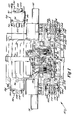
- Figure 1 shows a side view of a preferred form of a combination clutch/brake in accordance with the present invention, with portions thereof being shown in section and with portions thereof being exploded therefrom,
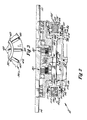
- Figure 2 shows a partial, cross-sectional view of an alternate form of the combination clutch/ brake of Figure 1, and
- Figure 3 shows a partial, side view of a pressure plate of the combination clutch/brake of Figures 1 and 2.
- All Figures are drawn for ease for explanation of the basic teachings of the present invention only; the extensions of the Figures with respect to number, position, relationship, and dimensions of the parts to form the preferred embodiment will be explained or will be within the skill of the art after the following teachings of the present invention have been read and understood. Further, the exact dimensions and dimensional proportions to conform to specific force, weight, strength, and similar requirements will likewise be within the skill of the art after the following teachings of the present invention have been read and understood.
- Where used in the various Figures of the drawings, the same numerals designate the same or similar parts. Furthermore, when the terms "top", "bottom", "first", "second", "inside", "inward", "outside", and similar terms are used herein, it should be understood that these terms have reference only to the structure shown in the drawings as it would appear to a person viewing the drawings and are utilized only to facilitate describing the invention.
- A rotational control apparatus of the type of a combination clutch/brake in accordance with the present invention is shown in the drawings and is generally designated 10. Clutch/brake 10 generally includes a
power input shaft 12 and anoutput shaft 14 which are rotatably mounted inhousing 26 by suitable bearings such thatshafts housing 26 are rotatably mounted with respect to each other.Input shaft 12 carries a first rotational interfacing element shown as aclutch spider 16 engaged with alternate disks 18 of adisk pack 20 which has interveningdisks 22 keyed to outputshaft 14. A second rotational interfacing element is shown as a brake spider 24 fixed tohousing 26 and carryingdisks 28 of adisk pack 30 which has intervening disks 32 keyed tooutput shaft 14. In its most preferred form. clutch/brake 10 is shown as being of the closed, oil film interface type which is particularly adaptable for use in environments such as in the food industry where it is extremely undesirable for worn interface particles to exit the apparatus, in environments where the low replacement of oil film interfaces is desirable, and/or in environments where high torque requirements of multiple interfaces is desirable. It can then be appreciated that these oil film type rotational interfacing elements of clutch/brake 10 can take other forms and constructions than the preferred form shown in the drawings. For example,disk packs - Clutch/brake 10 includes a spool-
shaped interfacing member 34 located between and reciprocal to engage eitherdisk pack member 34 includes a first pressure plate 36 and asecond pressure plate 38 interconnected for axial movement together and for allowing relative rotation with respect to each other by a bearing 40. Pressure plate 36 in its most preferred form is annular in shape having an L-shaped cross section and includes an axially extending cylinder 42 keyed tooutput shaft 14 by splines 43 and a radially extending disk 44. Disc 44 includes a first radially extending surface 46 for abutting or interfacing withdisk pack 20 and a second radially extending surface having circumferentially spaced, radially extending fins 48. Bearing 40 is retained on cylinder 42 by ashoulder 50 formed integrally with disc 44 and aretaining ring 52 received in an annular cavity formed in cylinder 42. -
Pressure plate 38 in its most preferred form is annular in shape having a generally L-shaped cross section and includes an axially extending cylinder 54 having first and second diametricallyopposed ears 56 extending radially from the outer surface thereof.Plate 38 further includes in its most preferred form anannular element 58 having a generally L-shaped cross section. Specifically,element 58 includes a radially extending disk 60 having a first radially extending surface 62 for abutting or interfacing withdisk pack 30 and an axially extending cylinder 64 having its outer surface integrally connected to the inside surface of cylinder 54. Bearing 40 is retained on cylinder 54 by shoulder 66 formed by the axial end of cylinder 64 opposite to disk 60 and by aretaining ring 68 received in an annular cavity formed in cylinder 54. - Clutch/brake 10 includes first and second actuating
rods 70 axially extending throughears 56 ofpressure plate 38 ofinterfacing member 34. Actuatingrods 70 are reciprocally mounted inhousing 26 by bushing 72.Pressure plate 38 is fixed to actuatingrods 70 by retainingrings 74 received in cavities formed inrods 70 on opposite sides ofears 56. In the most preferred form of the present invention,abutment washers 76 are provided on opposite sides ofears 56 andintermediate ears 56 and retainingrings 74. In the most preferred form.rods 70 have a length such thatopposite ends rods 70 are located axially inward ofbushings 72. - Actuating
rod 70 is operated in both directions byactuation canisters 82.Canisters 82 generally include a cup-shaped member 84 having a generallycylindrical wall 86, a generally circular, closedbottom 88. and a generally circular, open top 90. Member 84 further includes mountingflanges 92 for receiving bolts 94 threadably received inhousing 26 for purposes of removably securingcanisters 82 to housing 26. Afluid communication port 96 is formed inwall 86 andbottom 88 of member 84. -
Actuation canisters 82 further include a piston 98 having a shape and size for reciprocal receipt inwall 86 of cup-shaped member 84 and in its most preferred form is circular. An axially extendingplunger rod 100 is integrally formed with piston 98 and extends through anaperture 102 formed inbottom 88 of member 84.Rod 100 has a size and shape for receipt withinbushings 72 ofhousing 26 and for abutting withends rods 70. -
Actuation canisters 82 further include aclosure 104 having a shape and size complementary towall 86 of member 84 for closing open top 90 thereof. In its most preferred form,closure 104 includes an axially extending spring recess 106. Afluid communication port 108 is formed inclosure 104. Closure 104 is secured to member 84 bybolts 110. Suitable sealing means is provided incanisters 82 to define a firstfluid pressure chamber 112 defined between piston 98 andclosure 104 and a secondfluid pressure chamber 114 defined betweenbottom 88 of member 84 and piston 98. -
Actuation canisters 82 includemembers 116 for biasing piston 98 towardsbottom 88 of member 84 shown in its preferred form as a spring in compression between piston 98 and recess 106 ofclosure 104. In the most preferred form,port 96 is open to the atmosphere and acts as a bleeder outlet to preventfluid pressure chamber 114 from having a pressure differential from atmospheric.Port 108 is in fluid communication with a source of fluid pressure. In a first preferred form of the present invention.springs 116 ofcanisters 82 have a relatively low compressional strength generally of the range which is less than required to actuate clutch/brake 10 but which is sufficient to moverod 70 to a neutral. unactivated position. It can then be appreciated that if eachrod 70 of clutch/brake 10 includes a pair ofcanisters 82 havingneutral springs 116 abutting on opposite ends 78 and 80 ofrod 70, in the absence of fluid pressure,rod 70 is located in a central position with interfacingmember 34 located intermediate disk packs 20 and 30. - In another preferred form of the present invention, springs 116' of canisters 82' have a compressional strength generally in the range required to actuate clutch/brake 10 and which is thus sufficient to move
rod 70 to an activated position. It can then be appreciated that if eachrod 70 of clutch/brake 10 includes a canister 82' having actuation springs 116' abutting on oneend rod 70 and acanister 82 having aneutral spring 116 abutting on theother end rod 70, in the absence of fluid pressure,rod 70 will be biased in an actuation position with interfacingmember 34 interfacing with one of disk packs 20 and 30 depending upon which end 78 or 80 canister 82' is located. - Now that the construction of clutch/brake 10 has been set forth, the operation and subtle features of clutch/brake 10 can be set forth and appreciated. In operation, with
rods 70 located in a centered condition, interfacingmember 34 is located intermediate and in a normal, non-actuated relation with disk packs 20 and 30 due to its interconnection torods 70 byears 56. Thenrods 70 are simultaneously axially moved by pushingends 80 ofrods 70 axially inward intohousing 26 and to the right in Figure 1. interfacingmember 34 which is interconnected torods 70 is moved axially such that surface 46 of pressure plate 36 abuts with andsandwiches disks 18 and 22 ofdisk pack 20 together thereby rotatably relatinginput shaft 12 tooutput shaft 14 and thereby clutching in the output to the input of clutch/brake 10. Conversely, whenrods 70 are simultaneously axially moved by pushingends 78 ofrods 70 axially inward intohousing 26 and to the left in Figure 1, interfacingmember 34 which is interconnected torods 70 is moved axially such that surface 62 ofpressure plate 38 abuts with andsandwiches disks 28 and 32 ofdisk pack 30 together thereby rotatably relatingoutput shaft 14 tohousing 26 and thereby braking the output of clutch/brake 10. - It can then be appreciated that interfacing
member 34 is interconnected torods 70 without allowing relative movement therebetween, such as pivotal movement. This type of interconnection betweenmember 34 androd 70 allows the use of retainingrings 74 andwashers 76 as in the preferred form of clutch/brake 10. - It can be realized that a retaining ring-type securement is relatively inexpensive compared to interconnections which allow relative movement such as pivotal. and which typically require a pin pressed through the rod to form a universal type of interconnection. Furthermore, a retaining ring-type securement is extremely easier to manufacture and with closer tolerances than interconnections allowing relative movement.
- Further, due. to the direct interconnection of
member 34 androd 70, it is relatively easy to include a factory designed calibration for clutch/brake 10 and to position interfacingmember 34 in a neutral position in clutch/brake 10 than prior clutch/brakes of this construction. For example, some prior clutch/brakes included pivotal actuation of the interfacing member which required individual adjustment according to manufacturing tolerances and wear and often resulted in drag of the interfacing member with the clutch or brake disk packs in a "neutral position". With clutch/brake 10, interfacingmember 34 can be engineered to be positioned between disk packs 20 and 30 whenrods 70 are centered inhousing 26 of clutch/brake 10. - Additionally, the particular construction of interfacing
member 34 is further advantageous. Particularly,pressure plates 36 and 38 can be easily and very economically cast. Specifically,pressure plates 36 and 38 do not include any internal cavities, intricate angles or portions, and like structural components which are expensive to cast or result in high rejection rates but ratherpressure plates 36 and 38 are formed with easily castable shapes. - In its most preferred form,
housing 26 is filled with lubricating oil for lubricating and cooling the internal components of clutch/brake 10. It should then be noted when pressure plate 36sandwiches disk pack 20 thus rotatably relatingshafts housing 26,pressure plate 38, actuatingrods 70, and like rotationally stationary parts in the preferred form described. Fins 48 which are integrally formed in pressure plate 36 rotate insidehousing 26 and mistify the oil withinhousing 26. Therefore, the lubricating qualities of the oil are increased as a result thereof reducing wear to the internal components of clutch/brake 10. This is especially advantageous with respect to bearing 40 located closely axially adjacent to fins 48 and which allows relative rotation betweenpressure plates 36 and 38 wheninput shaft 12 is clutched in withoutput shaft 14. - Additionally, it should be appreciated that when
output shaft 14 is stationary or in other words in the same rotational position ashousing 26,pressure plates 36 and 38 do not rotate with respect to each other such that bearing 40 does not operate. Therefore, bearing 40 does not operate when clutch/brake 10 is in a neutral or brake actuation position and thus reducing bearing wear and increasing bearing life. It should be further appreciated that this non-operation of bearing 40 during the neutral and brake actuation position of clutch/brake 10 further enhances bearing life in addition to the bearing life enhancement produced by the increased lubricating effect of the oil due to its mistifying by fins 48 with pressure plate 36 of interfacingmember 34. In the first preferred form of the present invention, actuation ofrods 70 is accomplished utilizingactuation canisters 82 havingneutral springs 116 at both ends 78 and 80 ofrods 70. If fluid pressure is introduced throughport 108 intofluid pressure chamber 112 ofcanisters 82 havingplunger rod 100 abutting with ends 78 ofrods 70.rods 70 are moved to the left in Figure 1 thus moving interfacingmember 34 tosandwich disk pack 30 andbraking output shaft 14 by rotationally interrelating it tohousing 26. When fluid pressure is released fromfluid pressure chamber 112, springs 116 ofcanisters 82 havingplunger rod 100 abutting with ends 80 ofrods 70move rods 70 to their neutral position where springs 116 ofcanisters 82 on opposite ends 78 and 80 ofrod 70 balance each other out. Likewise, if fluid pressure is introduced throughport 108 intofluid pressure chamber 112 ofcanisters 82 havingplunger rod 100 abutting with ends 80 ofrods 70,rods 70 are moved to the right in Figure 1 thus moving interfacingmember 34 tosandwich disk pack 20 and clutching inoutput shaft 14 by rotationally interrelating it to inputshaft 12. When fluid pressure is released fromfluid pressure chamber 112, springs 116 ofcanisters 82 havingplunger rod 100 abutting with ends 78 ofrods 70move rods 70 to their neutral position where springs 116 ofcanisters 82 on opposite ends 78 and 80 ofrod 70 balance each other out. - In the other preferred form of the present invention, actuation of
rods 70 is spring set and is accomplished utilizing actuation canister 82' having actuation springs 116' abutting with one of ends 78 and 80 ofrods 70 and havingactuation canister 82 havingneutral springs 116 abutting with the other ends 78 and 80 ofrods 70. For example, with actuation canisters 82' havingplunger rods 100 abutting with ends 78 ofrods 70 and withactuation canisters 82 havingplunger rods 100 abutting with ends 80 ofrods 70,rod 70 will be biased to the left in Figure 2 such that interfacingmember 34sandwiches disk pack 30braking output shaft 14 by rotationally interrelating it tohousing 26. Thus, with this arrangement, clutch/brake 10 is in a spring set, braking condition. If fluid pressure is introduced throughport 108 intofluid pressure chamber 112 ofcanisters 82 havingplunger rod 100 abutting with ends 80 ofrods 70,rods 70 are moved to the right in Figure 2 and against the bias of springs 116' of canisters 82' thus moving interfacingmember 34 tosandwich disk pack 20 and clutching inoutput shaft 14 by rotationally interrelating it to inputshaft 12. When fluid pressure is released fromfluid pressure chamber 112 ofcanisters 82, springs 116' of canisters 82' havingplunger rod 100 abutting with ends 78 ofrods 70return rods 70 to its spring set braking condition due to the greater strength of springs 116' thansprings 116. It should also be realized that fluid pressure may be introduced throughport 108 intofluid pressure chamber 112 of canisters 82' havingplunger rod 100 abutting with ends 78 ofrods 70 to assist or boost springs 116' in movingrods 70 to their spring set, braking condition. - It should then be realized that actuation canisters 82' having actuation springs 116' may be positioned to abut with ends 80 of
rods 70 and withactuation canisters 82 havingneutral springs 116 positioned to abut with ends 78 ofrods 70 such thatrods 70 are biased to the right in Figure 2 such that interfacingmember 34sandwiches disk pack 20 clutching inoutput shaft 14. Thus, with this arrangement, clutch/brake 10 is in a spring set, clutching condition. If fluid pressure is introduced throughport 108 intofluid pressure chamber 112 ofcanisters 82 havingplunger rod 100 abutting with ends 78 ofrods 70,rods 70 are moved to the left in Figure 2 and against the bias of springs 116' of canisters 82' thus moving interfacingmember 34 tosandwich disk pack 30 andbraking output shaft 14 by rotationally interrelating it tohousing 26. When fluid pressure is released fromfluid pressure chamber 112, springs 116' of canisters 82' havingplunger rod 100 abutting with ends 80 ofrods 70return rods 70 to its spring set, clutching condition due to the greater strength of springs 116' thansprings 116. It should also be realized that fluid pressure may be introduced throughport 108 intofluid pressure chamber 112 of canisters 82' havingplunger rod 100 abutting with ends 80 ofrods 70 to assist or boost springs 116' in movingrods 70 to their spring set, clutching condition. - For purposes of illustration, an example of valve means useable to actuate clutch/brake 10 having canisters 82' will be described and it can be realized that other forms of actuation will be available. Specifically, the valve means may have at least three conditions where in a first condition, fluid from a source of fluid under pressure is directed to port 108 of
canister 82 while any fluid pressure ofchamber 112 is released throughport 108 of canister 82' for movingactuating rod 70 against bias ofsprings 116'. in a second condition any fluid is released fromchamber 112 throughport 108 ofcanister 82 allowingactuating rod 70 to move under the bias ofsprings 116'. and in a third condition where fluid is also released fromchamber 112 throughport 108 ofcanister 82 but where fluid from a source of fluid under pressure is directed to port 108 of canister 82' for assisting springs 116' in movingactuating rods 70. It can be appreciated that in the second condition. any fluid pressure ofchamber 112 of canisters 82' may be released throughport 108. Likewise. the vai,,e means useable to actuate clutch/brake 10 havingcanisters 82 at both ends 78 and 80 ofactuating rods 70 may have at least three conditions where in a first condition, fluid from a source of fluid under pressure is directed to port 108 ofcanister 82 movingend 78 ofrods 70 while any fluid pressure ofchamber 112 ofcanister 82 movingend 80 ofrods 70 is released throughport 108 for movingend 78 of actuatingrod 70 axially inwardly, where in a second condition any fluid pressure ofchambers 112 of bothcanisters 82 is released throughports 108 allowingsprings 116 to center or axially balance actuatingrods 70, and where in a third condition. fluid from a source of fluid under pressure is directed to port 108 ofcanister 82 movingend 80 ofrods 70 while any fluid pressure ofchamber 112 ofcanister 82 movingend 78 ofrods 70 is released throughport 108 for movingend 80 of actuatingrod 70 axially inwardly. - It can then be realized that clutch/brake 10 may be set up at the factory. at the warehouse or parts supply site. or at the field to be either in a spring set clutching condition. a spring set braking condition. or a neutral condition by the selection and arrangement of
canisters 82 and 82' utilized. Further. canisters 82' which achieve a spring set condition are identical tocanisters 82 which achieve a neutral set condition except for the substitution of a high compression, actuation-type spring 116' for a low compression neutral-type spring 116. It can then be appreciated that the modular construction of clutch/ brake 10 is particularly advantageous. First, it should be realized that the only constructional difference between clutch/brake 10 in a spring set and a neutral actuation condition is the differences ofsprings 116 and 116'. Thus, it can be appreciated that since all parts are standardized, it is possible to manufacture all uniform parts, assemble the power capsule, i.e.housing 26 and all its internal components at the factory. Canister components can then be manufactured and assembled withsprings 116 or 116' according to demand. Likewise, reduced inventory is possible because it is only necessary to keep sufficient inventory ofactuation capsules 82 and 82' for attachment to assembled power capsules according to the actuation condition desired. Thus, manufacturing set up and inventory costs are substantially reduced. - Furthermore,
canisters 82 and 82' are further advantageous. In the event that it is necessary to replace a canister such as the result of canister leakage. it is only necessary to remove the defective canister and replace it with a similar operative canister. Thus, substantial down-time is saved because it is not necessary to disassemble any other portions of clutch/brake 10. The defective canister may then be disposed of or may be rebuilt at the field, the factory, or other location without a substantial interruption of machine time. - Further.
canisters 82 and 82' may remove the risk to mechanics in the field of explodingsprings 116 and 116' when disassemblingcanisters 82 and 82' as they may be simply tossed or may be factory rebuilt or rebuilt by trained personnel. Specifically. in disassembling prior clutch or brake units. often the springs would be released with great force especially in spring set conditions. Utilizingcanisters - Additionally, utilizing elongated. threaded
bolts 110 as in the preferred form ofcanisters 82 and 82' allow the compression ofsprings 116 and 116' to be substantially reduced beforeclosure 104 would be released from cup-shaped member 84 and thus releasingsprings 116 and 116' fromcanisters 82 and 82'. Thus, accidental release of a compressed spring is additionally reduced. - Furthermore, it is believed that the construction of
canisters 82 and 82' are also particularly advantageous. Specifically, member 84, piston 98, andclosure 104 may be easily and inexpensively cast andcanisters 82 and 82' may be easily assembled. - Furthermore,
canisters 82 and 82' include only four components which are of a simple design and which incorporate the spring mounts, the sealing provisions, the reciprocal mounting, and like functional requirements. - Additionally, springs 116 and 116'
bias rods 100 to extend outside ofcanisters 82 and 82' when detached fromhousing 26 of clutch/brake 10. - Since ends 78 and 80 of
rods 70 are located inwardly ofbushings 72, it is only necessary to sliderods 100 intobushings 72 such thatcanisters 82 and 82' are properly centered and aligned onhousing 26. Thus, the construction ofcanisters 82 and 82' and of actuatingrod 70 andbushings 72 allows for the rapid assembly of clutch/brake 10 and without encountering the time consuming alignment problems of prior rotational control apparatus. - Further, the ability to assist or boost springs 116' in moving
rods 70 to their spring engaged condition is also advantageous. Under most conditions, springs 116' have sufficient force to spring set clutch/brake 10. However, under certain conditions such as in emergency situations, it may be desirable to electively exert greater force to faster rotatably relateoutput shaft 14 by the spring set. To utilize a spring having the force desired in such emergency-type situations may result in greater wear and failure of the actuation components. Canisters 82' allow a smaller spring to be utilized for normal actuation situations but includes provisions for electively increasing the actuation force when the situation demands it and specifically utilizes fluid pressure to assist spring 116'. - Additionally, in a spring set environment, a sufficient force is then necessary to actuate clutch/ brake 10 against this spring set. Thus, the greater the compression strength of the spring, the greater the force is needed to counter the spring set force. In many environments, it is undesirable to include pistons having large areas and/or the source of fluid is under relatively low pressure. Thus, it can be appreciated that clutch/brake 10 utilizing
actuation canisters 82 and 82' is further advantageous. Specifically, when it is desired to moverod 70 against the bias of its spring set, any fluid pressure influid pressure chamber 112 of canister 82' is released such that the fluid pressure introduced intochamber 112 ofcanister 82 needs only to overcome the normal actuation force of spring 116' and particularly does not need to overcome the greater, emergency-type, actuation force of spring 116' assisted by fluid pressure. Thus, the size of pistons 98 ofcanisters 82 may be relatively small and the fluid may be under relatively low pressure in clutch/brake 10 while still allowing for elective, emergency-type, high force-type actuation. Now that the basic teachings of the present invention have been explained, many extensions and variations will be obvious to one having ordinary skill in the art. For example, although the teachings of the present invention have been shown and described in its preferred form as a combination clutch/brake, it can be appreciated that these teachings may be applicable in other forms and types of rotational control apparatus. As a further example, clutch/ brake 10 is shown as a closed, oil film interface-type apparatus in its most preferred form, the teachings of the present invention may be applicable to other forms of clutch/brakes such as frictional or toothed interface types. - Also, in the most preferred form of the present invention, several independent and inventive aspects have been incorporated into a single rotational control apparatus which is believed to be particularly advantageous. However, a person skilled in the art may apply one or more of these inventive aspects in a rotational control apparatus of the same or different type.
Claims (19)
Applications Claiming Priority (2)
| Application Number | Priority Date | Filing Date | Title |
|---|---|---|---|
| US806662 | 1985-12-09 | ||
| US06/806,662 US4648493A (en) | 1985-12-09 | 1985-12-09 | Rotational control apparatus |
Publications (2)
| Publication Number | Publication Date |
|---|---|
| EP0226440A2 true EP0226440A2 (en) | 1987-06-24 |
| EP0226440A3 EP0226440A3 (en) | 1987-11-25 |
Family
ID=25194551
Family Applications (1)
| Application Number | Title | Priority Date | Filing Date |
|---|---|---|---|
| EP86309590A Withdrawn EP0226440A3 (en) | 1985-12-09 | 1986-12-09 | Rotational control apparatus |
Country Status (5)
| Country | Link |
|---|---|
| US (1) | US4648493A (en) |
| EP (1) | EP0226440A3 (en) |
| JP (1) | JPS62165036A (en) |
| AU (1) | AU6619286A (en) |
| CA (1) | CA1280702C (en) |
Cited By (1)
| Publication number | Priority date | Publication date | Assignee | Title |
|---|---|---|---|---|
| WO1997036115A1 (en) * | 1996-03-26 | 1997-10-02 | Meritor Heavy Vehicle Systems, Llc | Plug-in hydraulic cylinder housing for hydraulically actuated clutch |
Families Citing this family (6)
| Publication number | Priority date | Publication date | Assignee | Title |
|---|---|---|---|---|
| US5823308A (en) * | 1996-02-16 | 1998-10-20 | Ladin; Eli M. | Clutch control with multiple actuating cylinders for a pull-type clutch |
| NO302501B1 (en) * | 1996-05-06 | 1998-03-16 | Mustad & Soen As | Method and own machine for fishing hooks |
| JP3542104B2 (en) * | 1998-10-19 | 2004-07-14 | 株式会社クボタ | Steering operation device for work equipment |
| US20060054426A1 (en) * | 2004-09-13 | 2006-03-16 | Fillmore Dale A | Braking apparatus and method of braking |
| US8967352B2 (en) | 2007-03-30 | 2015-03-03 | Eaton Corporation | Low driven inertia dual clutch |
| US8544627B2 (en) * | 2008-11-12 | 2013-10-01 | Horton, Inc. | Two-speed clutch and retro-fit kit |
Family Cites Families (32)
| Publication number | Priority date | Publication date | Assignee | Title |
|---|---|---|---|---|
| US843076A (en) * | 1904-02-15 | 1907-02-05 | Jacob S Detrick | Clutch-operating mechanism. |
| US976224A (en) * | 1909-03-29 | 1910-11-22 | St Clair Air Brake Company | Air-brake. |
| DE688749C (en) * | 1938-06-26 | 1940-03-01 | Lohmann & Stolterfoht A G | Friction disc clutch |
| US2304774A (en) * | 1941-02-11 | 1942-12-15 | Charles S Ash | Dual wheel assembly |
| US2386512A (en) * | 1943-04-02 | 1945-10-09 | Gen American Aerocoach Company | Clutch operating mechanism |
| US3163092A (en) * | 1960-10-28 | 1964-12-29 | Neway Equipment Co | Brake operating structure |
| US3347600A (en) * | 1965-03-11 | 1967-10-17 | Wagner Electric Corp | Pressure balanced spring applied brake system |
| US3309149A (en) * | 1965-12-03 | 1967-03-14 | Wagner Electric Corp | Combined service and emergency brake system |
| GB1122361A (en) * | 1966-02-09 | 1968-08-07 | Automobile Products Company Lt | Improvements in or relating to fluid pressure motors for producing straight-line motion |
| US3595353A (en) * | 1969-06-11 | 1971-07-27 | Verson Mfg Co | Couplings with stationary spring and fluid motor |
| US3580369A (en) * | 1969-06-27 | 1971-05-25 | Gen Motors Corp | Liquid-cooled disc brake assembly |
| US3805632A (en) * | 1969-09-29 | 1974-04-23 | Int Harvester Co | Automatic transmission with fluid operated freewheeling clutches |
| US3680666A (en) * | 1970-01-08 | 1972-08-01 | Sommer Co | Motor brake unit |
| DE2008052A1 (en) * | 1970-02-21 | 1971-09-02 | ||
| US3638773A (en) * | 1970-03-31 | 1972-02-01 | Force Control Ind | Clutch brake unit |
| US3653477A (en) * | 1970-07-21 | 1972-04-04 | Quinten A Hansen | Self-cooling clutch and brake |
| US3710902A (en) * | 1971-11-26 | 1973-01-16 | Q Hansen | Self-cooling clutch and brake |
| US3818804A (en) * | 1971-12-13 | 1974-06-25 | Weatherhead Co | Dual brake system |
| US3924715A (en) * | 1974-04-17 | 1975-12-09 | Force Control Ind | Clutch-brake unit |
| US3954304A (en) * | 1974-06-17 | 1976-05-04 | General Signal Corporation | Emergency and handbrake control system |
| US3986584A (en) * | 1975-03-20 | 1976-10-19 | Westinghouse Air Brake Company | Fail-safe disc brake with spring actuated slack adjuster |
| GB1504073A (en) * | 1975-08-27 | 1978-03-15 | Caterpillar Tractor Co | Annular single piston brake arrangement |
| SE395414B (en) * | 1975-12-05 | 1977-08-15 | Bromsregulator Svenska Ab | POWER LIMITING DEVICE FOR A PARKING BRAKE ACTUATOR IN SERIES WITH A SERVICE BRAKE ACTUATOR |
| JPS5931436B2 (en) * | 1977-02-25 | 1984-08-02 | 株式会社小松製作所 | Press machine brake device |
| JPS5418783A (en) * | 1977-07-12 | 1979-02-13 | Mitsubishi Electric Corp | Level display device |
| US4187931A (en) * | 1977-07-18 | 1980-02-12 | Caterpillar Tractor Co. | Brake housing and actuating mechanism |
| US4184573A (en) * | 1978-10-05 | 1980-01-22 | Walter Kidde & Company, Inc. | Double-acting disc brake having floating cylinder head |
| US4361078A (en) * | 1981-03-16 | 1982-11-30 | Wabco Ltd. | Hydraulic brake actuator having spring-applied back-up brake with manual release means |
| US4534454A (en) * | 1981-11-30 | 1985-08-13 | Horton Manufacturing Co., Inc. | Combination clutch-brake |
| US4560034A (en) * | 1982-03-05 | 1985-12-24 | Caterpillar Tractor Co. | Annular multi-piston brake apparatus |
| US4509627A (en) * | 1982-08-03 | 1985-04-09 | Aisin Warner Kabushiki Kaisha | Hydraulic centrifugal clutch |
| US4549639A (en) * | 1984-02-06 | 1985-10-29 | Hansen Quinten A | Clutch control for a rotation and reciprocation transmission |
-
1985
- 1985-12-09 US US06/806,662 patent/US4648493A/en not_active Expired - Lifetime
-
1986
- 1986-12-08 AU AU66192/86A patent/AU6619286A/en not_active Abandoned
- 1986-12-08 CA CA000524749A patent/CA1280702C/en not_active Expired - Lifetime
- 1986-12-09 JP JP61293322A patent/JPS62165036A/en active Granted
- 1986-12-09 EP EP86309590A patent/EP0226440A3/en not_active Withdrawn
Cited By (1)
| Publication number | Priority date | Publication date | Assignee | Title |
|---|---|---|---|---|
| WO1997036115A1 (en) * | 1996-03-26 | 1997-10-02 | Meritor Heavy Vehicle Systems, Llc | Plug-in hydraulic cylinder housing for hydraulically actuated clutch |
Also Published As
| Publication number | Publication date |
|---|---|
| JPS62165036A (en) | 1987-07-21 |
| CA1280702C (en) | 1991-02-26 |
| EP0226440A3 (en) | 1987-11-25 |
| US4648493A (en) | 1987-03-10 |
| JPH0318060B2 (en) | 1991-03-11 |
| AU6619286A (en) | 1988-06-16 |
Similar Documents
| Publication | Publication Date | Title |
|---|---|---|
| EP1255934B1 (en) | Combined parking and service brake | |
| US5189930A (en) | Vehicle power transmitting mechanism | |
| US5752810A (en) | Pump with an integral clutch | |
| EP0282169B1 (en) | Clutch assembly with a pressure-balance chamber | |
| EP0718520B1 (en) | Wet clutch assembly | |
| US4811614A (en) | Power take-off drive unit | |
| EP0081450B1 (en) | Combination clutch-brake | |
| EP1445506A1 (en) | Multi-disk friction device with selective lubrification on demand | |
| US3863746A (en) | Centrifugally balanced rotating clutch | |
| GB1560018A (en) | Drive mechanism | |
| US4696378A (en) | Axially compact brake | |
| US3243026A (en) | Hydraulic clutch with multiple pistons | |
| US4648493A (en) | Rotational control apparatus | |
| US4186827A (en) | Fluid operated clutch and brake | |
| US4766986A (en) | Rotational control apparatus | |
| US4872535A (en) | Brake | |
| US3773157A (en) | Clutch with coolant cut-off valve | |
| US4657126A (en) | Two-speed clutch | |
| US4627302A (en) | Countershaft transmission | |
| US4750595A (en) | Rotational control apparatus | |
| US5704461A (en) | Rotational control apparatus | |
| US4708231A (en) | Centrifugal clutch | |
| GB2191252A (en) | Friction clutch | |
| US6755289B2 (en) | Rotational control apparatus | |
| US6786313B2 (en) | Rotational control apparatus |
Legal Events
| Date | Code | Title | Description |
|---|---|---|---|
| PUAI | Public reference made under article 153(3) epc to a published international application that has entered the european phase |
Free format text: ORIGINAL CODE: 0009012 |
|
| AK | Designated contracting states |
Kind code of ref document: A2 Designated state(s): BE DE ES FR GB IT SE |
|
| PUAL | Search report despatched |
Free format text: ORIGINAL CODE: 0009013 |
|
| AK | Designated contracting states |
Kind code of ref document: A3 Designated state(s): BE DE ES FR GB IT SE |
|
| STAA | Information on the status of an ep patent application or granted ep patent |
Free format text: STATUS: THE APPLICATION IS DEEMED TO BE WITHDRAWN |
|
| 18D | Application deemed to be withdrawn |
Effective date: 19880526 |
|
| RIN1 | Information on inventor provided before grant (corrected) |
Inventor name: SCHILLING, HUGH K. Inventor name: RAINES, CHARLES D. Inventor name: DAYEN, LEONID |