EP0225494B1 - Improved machine manufacturing paper bags containing some substance to prepare infusions or infused beverages (as coffee or tea) - Google Patents
Improved machine manufacturing paper bags containing some substance to prepare infusions or infused beverages (as coffee or tea) Download PDFInfo
- Publication number
- EP0225494B1 EP0225494B1 EP86115564A EP86115564A EP0225494B1 EP 0225494 B1 EP0225494 B1 EP 0225494B1 EP 86115564 A EP86115564 A EP 86115564A EP 86115564 A EP86115564 A EP 86115564A EP 0225494 B1 EP0225494 B1 EP 0225494B1
- Authority
- EP
- European Patent Office
- Prior art keywords
- ribbon
- openings
- disc
- vacuum
- base plate
- Prior art date
- Legal status (The legal status is an assumption and is not a legal conclusion. Google has not performed a legal analysis and makes no representation as to the accuracy of the status listed.)
- Expired - Lifetime
Links
Images

Classifications
-
- B—PERFORMING OPERATIONS; TRANSPORTING
- B65—CONVEYING; PACKING; STORING; HANDLING THIN OR FILAMENTARY MATERIAL
- B65B—MACHINES, APPARATUS OR DEVICES FOR, OR METHODS OF, PACKAGING ARTICLES OR MATERIALS; UNPACKING
- B65B9/00—Enclosing successive articles, or quantities of material, e.g. liquids or semiliquids, in flat, folded, or tubular webs of flexible sheet material; Subdividing filled flexible tubes to form packages
- B65B9/02—Enclosing successive articles, or quantities of material between opposed webs
- B65B9/04—Enclosing successive articles, or quantities of material between opposed webs one or both webs being formed with pockets for the reception of the articles, or of the quantities of material
- B65B9/042—Enclosing successive articles, or quantities of material between opposed webs one or both webs being formed with pockets for the reception of the articles, or of the quantities of material for fluent material
Definitions
- the present invention relates to a machine for packaging filter paper pockets or bags containing substances, powdered or in the form of small leaves, for the preparation of infusions.
- the present invention relates to a machine for the packaging of filter-paper pockets containing a tablet of fresh coffee powder, the said pockets being joined together to form a strip or continuous ribbon which feeds intermittently an infusion unit of the usual type for the preparation of expresso coffee.
- Machines for the preparation of expresso coffee are known and have acquired widespread use especially in the form of automatic distributors operated by coins or tokens.
- Machines are also known for filling continuous strips of paper which have at regular intervals filter pockets containing freshly ground coffee.
- the above mentioned machines include a chain of plates, movable across said traversing table, and closed according to a planar loop, on which operates a plruality of operating members performing the above mentioned operations. Even if said kind of machine is successful in executing any necessary operation for the packaging of paper pockets, however, as the above operating members are all connected and moved in unison by a large vertically movable plate structure (see Figures 1 and 2) covering the whole extension of said chain of plates, such a plate structure being also doubled for having a high enough production speed is so bulky and heavy that this results in strong vibrations, limiting substantially the working speed thereof and needing a retaining mechanism in the form of retaining rings to fasten the lower paper ribbon to the chain of plates, said retaining rings being possibly a danger for the integrity of the lower paper ribbon.
- the machine of GB-A-1,011,872 corresponds to the features defined in the first part of claim 1.
- Said patent discloses a machine for filling said pockets or bags of filter paper with a measure of the substance, and then sealing the bags from which the infusion is to be obtained, said machine comprising a conveyance table on which advances in steps a plurality of jaw devices, equivalent to the movable plates with retaining rings of GB-A-1011872, having a jaw moving between an open position and a closed position in relation to a fixed jaw, said table being arranged beneath a series of processing devices comprising first means forming lower cavities in the lower paper ribbon fed upstream on said lower jaw, a metering device for the fresh coffee powder, a pressing member for the measure of coffee powder deposited on lower paper ribbon advancing intermittently, means for feeding and positioning the upper layer of paper of said pocket, and thermosealing means, said jaw devices comprising magnetically controlled means tending to hold said moving jaw, closed against said fixed jaw while between said fixed jaw and said moving jaw is interposed said lower or supporting paper ribbon and with said moving jaw there is integral a drive pin engaged by cam means which drive the moving jaw
- An object of the present invention is to provide an improved machine for packaging filter pockets or bags of the abovementioned type and, in particular, a mechanism without jaws which would however permit holding firmly said first strip during the various pocket forming erations.
- Another specific object of the present invention is to shorten as much as possible the chain or cups without jaws, using a tool which performs simultaneously with a single action the highest possible number of operations.
- Another object of the present invention is to press the powder designed to fill said pockets in such a manner as to form a layer of the most uniform thickness possible.
- Another specific object of the present invention is to return all the coffee powder particles to within the layers or ribbons forming the pockets in such as a manner as to eliminate all scattering of powder and hence the formation of defective pockets.
- said apparatus comprising a stationary supporting table on which advances in steps a plurality of shallow cup devices each formed of an essentially quadrangular plate having a central depression with rounded edges, the bottom of said depression having holes through which a vacuum may be applied, said supporting table being provided with vacuum openings extending therethrough so as to from a sliding connection with the holes in the said depressions, the said supporting table being positioned below a first and second processing device the first processing device comprising a unitary mould and the second processing device comprising a forming and sealing memberto shape and seal the upper ribbon to the lower ribbon, the cup devices further being connected each other so as to form a closed loop, characterized in that the said cup devices have no mechanical means to fasten said paper ribbon thereto, the adhesion between
- the apparatus for filling pockets is characterized in that the conveying and measuring device is of rotating kind comprising a disc of appropriate thickness, contained between said base plate or sole and said cover, having openings (122-126) passing from face to face through said disc which rotates about a shaft pivotted in the cover of said unitary mould in such a manner that the bottom face of said disc slides in contact with an upper face of the base plate of said mould, said openings acting as conveying cavities for powder measures, coming from a metering mechanism (130), having the duty of delivering into each opening, as it passes thereunder, such a quantity of powderto fill said, openings, to a lower opening through said base plate (66) connecting one of the openings in the disc with one of the underlying flat cup devices to permit transfer of said powder from the openings in the conveying disc to the recess in the lower paper ribbon resting on the bottom of the depression of one of the cup devices.
- the conveying and measuring device is of rotating kind comprising a disc of appropriate thickness, contained between said base plate or sole and said cover,
- the apparatus for filling pockets is preferably characterized in that the disc with openings, in addition to sliding in contact with the upper face of the base plate of the unitary mould is closed at the top and sides by said cover covering said unitary mould in such a manner to eliminate any powder spread by said measuring and conveying devices, said cover having a first hole allowing entry of the powder into one of the openings in the disc and a second hole aligned with the said hole in the base plate.
- said vacuum stopping and resumption is performed by means of a valve mechanism of the kind preferably having a rotating valve comprising a cylindrical reel rotating by means of a shaft, connected to and synchronizing said tamper, within a cylindrical case, the shaft rotating said cylindrical reel, being linked by a gear assembly to the position of the conveying disc for having the vacuum stopped and resumed in the required manner.
- a valve mechanism of the kind preferably having a rotating valve comprising a cylindrical reel rotating by means of a shaft, connected to and synchronizing said tamper, within a cylindrical case, the shaft rotating said cylindrical reel, being linked by a gear assembly to the position of the conveying disc for having the vacuum stopped and resumed in the required manner.
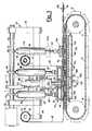
- the machine in accordance with the invention comprises a conveyor chain 10 the links of which are formed of cup devices 12 better illustrated in Fig. 2.
- the conveyor chain is driven by a drive roller 14 in the direction of the arrow 16 and closes on an idling roller 18.
- the operating travel of the chain 10 takes place on the supporting table shown schematically in Fig. 1 with the number 22.
- a detailed description thereof is omitted except as specifically pertains ot the cup devices and the other features forming the object of the present invention.
- a frame 24 presenting two uprights 26 and 28 which support in a rotating manner a cam shaft 30 driven by a reducing gear 32 and bearing a plurality of cams 34, 36, 38 and 40 for the purpose indicated below, said cams being synchronized together in relation to the operation of the various members and devices controlled thereby.
- Number 42 indicates a roll of filter-paper ribbon mounted in a rotating manner on a paper-holding reel 44 which is born by a bracket 46. From the roll 42 is taken, the filter-paper ribbon 48, designed to form the lower or supporting ribbon of the strip of filter pockets or bags indicated generally by number 50 at the right end of Fig. 1, each pocket 50 comprising a cavity formed by said lower filter-paper ribbon 48, an upper or closing filter-paper ribbon 52 and a tablet measure of fresh coffee powder 54.
- the filter-paper ribbon 52 is taken from a roll 56 mounted in a freely rotating manner on a reel or mandrel 58 born by a support 60. Now considering all the figures, it is seen that on the crosspiece 62 of the frame 24 there are mounted in order (1) a unitary mould 64 the purpose of which is to preform and fill with coffee powder the lower filter-paper ribbon, (2) a forming and sealing member 140 having the purpose of shaping and sealing the upper ribbon 52 of filter paper to the lower ribbon 48 to form a pocket 50.
- the unitary mould 64 is formed of a base plate or sole 66, a hole 70 for passage of measures of coffee powder 72, and a tamper 74 with an overturned cup, said tamper being supported by a shaft 76, by a cover 78, by two stems 80 and 82 integral with said cover and driven through conventional motion transmission mechanism 84 and 86 fitted with a springs to hold the stems 80 and 82 lifted against the cams 34 and 38 respectively.
- the tamper 74 mounted on the rotating shaft 76 is driven in its reciprocating movement by a stem 88 equipped with a side protuberance 90 designed to engage with a shaped groove 92 made in the cam 36 in such a manner as to permit positive engagement of said cam with the stem 88 in both directions of its reciprocating movement.
- Said stem 88 is fitted in a sliding manner in a sheath 94 fixed to the cross piece 62 and is fitted in its lower part with a thrust bearing 96 designed to connect said stem 88 with the rotating shaf 76 in such as a manner as to permit it free rotation and reciprocating movement conferred by the stem 88.
- the shaft 76 has grooves 98 which permit axially sliding engagement with a sprocket 100 which is driven in turn by a gear assembly which be explained in greater detail here below.
- the sprocket 100 is housed in a seat formed by an upper flange 102 and a lower flange 104 which is in turn fixed to a cylindrical casing 106 bearing inside a reel 108 and forming a rotating distribution valve assembly 110 having the purpose which will be explained here below.
- the cover 78 of the unitary mould 64 contains a member for conveyance of the coffee powder measures formed by a disc 120 traversed by the openings 122,124,126 designed to receive one measure of freshly ground coffee each coming from a delivery system 130 connected to known grinding means such as the means 132 shown in outline in Fig. 1.
- the disc 120 is integral with a shaft pivoted in the base plate sole 66 and in the cover 78 of the unitary mould 64 and moves in steps covering angles corresponding to the distance between two adjoining openings in the disc in such a manner as to permit stopping and alignment of said openings with the system 130 which delivers coffee and with the hole 70 in the base plate 66 respectively to permit passage of the ground coffee first from the delivery system 130 to the openings in the disc and then from the openings in the disc to the hole 70 in the base plate 66 for the purpose of depositing said measure of coffee on the filter-paper ribbon 48 supported on a cup device 12.
- the opening in the disc 120 as the opening 128, which at that moment is aligned with the hole 70 and with the tamper 74, is traversed by said tamper which pushes and tamps all the coffee powder on the ribbon 48. Subsequently the tamper 74 withdraws and frees the opening 128 of the disc 120 which can thus rotate to a subsequent position.
- the chain 10 in its step movement following the direction indicated by the arrows 16 brings the lower ribbon 48 with the measure of tamped coffee out of the unitary mould 64 to meet an upper covering ribbon 52, also of filter paper, which is superimposed on the lower ribbon 48 and is sealed therewith by a forming and sealing member 140 made up of a flat plate having tray- like recesses similar to those of the cup device 12 and heated in the conventional manner to permit the thermosealing of the two filter-paper ribbons, said forming and sealing member being of the type known in the prior art.
- the forming and sealing member 140 is fixed to a stem 142 which, through a motion transmission mechanism 144 fixed to the crosspiece 62, rests on the cam 40 receiving therefrom a reciprocating movement which causes the member 140 to rotate between its lower position, represented in solid lines, and an upper position 140a represented in broken lines.
- the paper ribbon bearing the filled pockets 50 moves to subsequent stations for punching of holes or perforation of weakening zones to aid tearing as well as shearing of the individual pockets for preparation thereof in the package forms required by the market.
- a particularly interesting feature of the present invention is provided by the support table 22 on which slides the chain 10 bearing the cup devices 12 beneath the unitary mould 64 and beneath the forming and sealing member 140.
- Said support table 22 is fitted underneath with ducts 148 communicating with a cover 150 divided in two compartments 152 and 154 separated by a partition 156 and communicating with the two respective sources of vacuum of which the one connected with the compartment 152 operates intermittently and the one connected with the compartment 154 operates continuously.
- the compartments 152 are connected to a general source of vacuum through a duct 158 which, through a pipe 162, passes through the distribution valve 110 which permits vacuum only at certain times, while the compartment 154 is connected permanently through a duct 160 to said general vacuum source.
- said valve is formed of a cylindrical reel 108 rotating by means of the action of the shaft 76 within the cylindrical casing 106 with smooth interior walls which form a seal with said reel 108.
- Said reel has protuberances or lands 112 and lowerings or recesses, such as the recess 114, which permit intermittent communication linked with a portion of the shaft 76, between a duct 170 connected with the general vacuum source and the abovesaid pipe 162 in such a manner as to apply to the compartments 152 an intermittent vacuum linked with the rotation of said shaft 76.
- the ribbon 48 is preformed by the vacuum of the bottom of the depressions any by the protuberance 68.
- the preshaped ribbon is loaded with a measure of coffee powder 72 which is subsequently packed by the tamper 74 with overturned cup which evens completely said measure of coffee.
- the vacuum is stopped by the distribution valve 110 to avoid dispersal and uneven tamping of said powder.
- the ribbon 48 bearing the load of coffee powder, is covered by the upper ribbon 52 which is subsequently welded to the lower ribbon 48 by the forming and sealing member 140 obtaining thereby the pocket 50.
- the completed ribbon containing the pockets 50 is provided with punched side holes and/or weakening perforations to permit their use and the formation of packages desired by market.
- the invention has been described for a machine for the preparation of strips of pockets for fresh coffee powder but only as an example, because the machine may be used in an essentially similar manner for the preparation of filter bags of other infusion substances such as tea, chamomile, and the like.
Landscapes
- Engineering & Computer Science (AREA)
- Mechanical Engineering (AREA)
- Packages (AREA)
- Containers And Plastic Fillers For Packaging (AREA)
- Bag Frames (AREA)
- Packging For Living Organisms, Food Or Medicinal Products That Are Sensitive To Environmental Conditiond (AREA)
- External Artificial Organs (AREA)
- Infusion, Injection, And Reservoir Apparatuses (AREA)
Abstract
Description
- The present invention relates to a machine for packaging filter paper pockets or bags containing substances, powdered or in the form of small leaves, for the preparation of infusions.
- More specifically the present invention relates to a machine for the packaging of filter-paper pockets containing a tablet of fresh coffee powder, the said pockets being joined together to form a strip or continuous ribbon which feeds intermittently an infusion unit of the usual type for the preparation of expresso coffee.
- These machines for the preparation of expresso coffee are known and have acquired widespread use especially in the form of automatic distributors operated by coins or tokens. Machines are also known for filling continuous strips of paper which have at regular intervals filter pockets containing freshly ground coffee.
- These machines, for example of the kind described and claimed in GB-A-1.011.872, published on December 1 1965, consist essentially of a traversing table, a lower ribbon of paper, having recesses formed at regular intervals in which a predetermined amount of coffee powder in the form of a tablet is deposited. On this lower ribbon there is superimposed an upper ribbon of paper which covers the individual tablets of fresh coffee powder, after which the two superimposed ribbons are welded, e.g. by thermosealing, along the entire periphery of each measure or tablet of fresh coffee powder.
- Further, the above mentioned machines include a chain of plates, movable across said traversing table, and closed according to a planar loop, on which operates a plruality of operating members performing the above mentioned operations. Even if said kind of machine is successful in executing any necessary operation for the packaging of paper pockets, however, as the above operating members are all connected and moved in unison by a large vertically movable plate structure (see Figures 1 and 2) covering the whole extension of said chain of plates, such a plate structure being also doubled for having a high enough production speed is so bulky and heavy that this results in strong vibrations, limiting substantially the working speed thereof and needing a retaining mechanism in the form of retaining rings to fasten the lower paper ribbon to the chain of plates, said retaining rings being possibly a danger for the integrity of the lower paper ribbon. The machine of GB-A-1,011,872 corresponds to the features defined in the first part of claim 1.
- "Further, when a measured charge of coffee powder is delivered on the lower paper ribbon by a coffee feeding mechanism, as the previously dimpled paper ribbon is kept in pocketed condition by a vacuum applied thereunder through vacuum ports in the movable plates (see page 5, lines 22-38 and Figure 5), being said paper ribbon, to allow an easy infusion, necessarily highly porous, it happens that the coffee particles impinge against the ribbon with a speed strongly increased by the suction due to the applied vacuum, so that the higher is the vacuum the faster the particles impinge against the ribbon, and for a vacuum high enough it is possible that, as some coffee particles can rebound against the first coffee layer on the ribbon, they spread all around and, specifically, some particles can fall on the sealing areas of the ribbon again, causing a subsequent defective thermosealing due to trapping of said particles in the sealing areas.
- One obvious remedy against such a problem could be to reduce the vacuum under the paper ribbon, but that could also reduce the retaining action of the ribbon on the movable plates.
- Actually that was attempted in a second and more recent example of packaging machine disclosed and claimed in the Italian Utility Model Patent No. 199.161 (former Application No. 23186 B/84 filed on September 18, 1984, open to the public since March 18, 1986) in the name of the applicant of the present Application".
- Said patent discloses a machine for filling said pockets or bags of filter paper with a measure of the substance, and then sealing the bags from which the infusion is to be obtained, said machine comprising a conveyance table on which advances in steps a plurality of jaw devices, equivalent to the movable plates with retaining rings of GB-A-1011872, having a jaw moving between an open position and a closed position in relation to a fixed jaw, said table being arranged beneath a series of processing devices comprising first means forming lower cavities in the lower paper ribbon fed upstream on said lower jaw, a metering device for the fresh coffee powder, a pressing member for the measure of coffee powder deposited on lower paper ribbon advancing intermittently, means for feeding and positioning the upper layer of paper of said pocket, and thermosealing means, said jaw devices comprising magnetically controlled means tending to hold said moving jaw, closed against said fixed jaw while between said fixed jaw and said moving jaw is interposed said lower or supporting paper ribbon and with said moving jaw there is integral a drive pin engaged by cam means which drive the moving jaw between the open and closed position.
- The machine described in the above mentioned patent operates in a rather satisfactory manner but there remains a certain complexity of operation linked to said jaw devices operating between open and closed position and the need of having a very long chain of said jaw devices because of the various phases comprising preforming the lower ribbon, metering and pressing the powder, feeding, positioning and forming the upper ribbon, and thermosealing the two ribbons in succession in distinct and contiguous stations or members of said machine.
- An object of the present invention is to provide an improved machine for packaging filter pockets or bags of the abovementioned type and, in particular, a mechanism without jaws which would however permit holding firmly said first strip during the various pocket forming erations.
- Another specific object of the present invention is to shorten as much as possible the chain or cups without jaws, using a tool which performs simultaneously with a single action the highest possible number of operations.
- Another object of the present invention is to press the powder designed to fill said pockets in such a manner as to form a layer of the most uniform thickness possible.
- Finally, another specific object of the present invention is to return all the coffee powder particles to within the layers or ribbons forming the pockets in such as a manner as to eliminate all scattering of powder and hence the formation of defective pockets.
- The above object are achieved by an apparatus for filling pockets on a lower filter paper ribbon with a measure of a substance, from which is to be made an infusion, said pockets being covered by an upper filter paper ribbon and then being sealed to form bags containing the substance, thereby forming a continuous strip of said bags, said apparatus comprising a stationary supporting table on which advances in steps a plurality of shallow cup devices each formed of an essentially quadrangular plate having a central depression with rounded edges, the bottom of said depression having holes through which a vacuum may be applied, said supporting table being provided with vacuum openings extending therethrough so as to from a sliding connection with the holes in the said depressions, the said supporting table being positioned below a first and second processing device the first processing device comprising a unitary mould and the second processing device comprising a forming and sealing memberto shape and seal the upper ribbon to the lower ribbon, the cup devices further being connected each other so as to form a closed loop, characterized in that the said cup devices have no mechanical means to fasten said paper ribbon thereto, the adhesion between the paper ribbon and the cups being provided solely by a vacuum applied through said supporting table openings to said holes in the depressions of said devices, said unitary mould comprising a one piece, vertically displaceable base plate or sole having integrally moulded therewith a first protuberance for pressing on the lower ribbon to cooperate with the vacuum applied to the bottom of the depressions of said cup devices so as to shape a recess in the lower ribbon, and in that a conveying and measuring device for said substance and a top cover of said mould, comprises a hole for the passage to the lower shaped ribbon of the measures formed by said measuring device and for the passage of a vertically movable and rotatable tamper which has an inverted cup shaped face which levels or evens the delivered measure on the said lower shaped ribbon and which completely detaches the said measure from said conveying and measuring means, the vacuum applied to the holes in the cup devices being controlled by a distribution valve to prevent the application of said vacuum to said holes when the measure is being delivered and tamped.
- Preferably the apparatus for filling pockets is characterized in that the conveying and measuring device is of rotating kind comprising a disc of appropriate thickness, contained between said base plate or sole and said cover, having openings (122-126) passing from face to face through said disc which rotates about a shaft pivotted in the cover of said unitary mould in such a manner that the bottom face of said disc slides in contact with an upper face of the base plate of said mould, said openings acting as conveying cavities for powder measures, coming from a metering mechanism (130), having the duty of delivering into each opening, as it passes thereunder, such a quantity of powderto fill said, openings, to a lower opening through said base plate (66) connecting one of the openings in the disc with one of the underlying flat cup devices to permit transfer of said powder from the openings in the conveying disc to the recess in the lower paper ribbon resting on the bottom of the depression of one of the cup devices.
- More specifically, the apparatus for filling pockets is preferably characterized in that the disc with openings, in addition to sliding in contact with the upper face of the base plate of the unitary mould is closed at the top and sides by said cover covering said unitary mould in such a manner to eliminate any powder spread by said measuring and conveying devices, said cover having a first hole allowing entry of the powder into one of the openings in the disc and a second hole aligned with the said hole in the base plate.
- Finally and more particularly said vacuum stopping and resumption is performed by means of a valve mechanism of the kind preferably having a rotating valve comprising a cylindrical reel rotating by means of a shaft, connected to and synchronizing said tamper, within a cylindrical case, the shaft rotating said cylindrical reel, being linked by a gear assembly to the position of the conveying disc for having the vacuum stopped and resumed in the required manner.
- The advantages of the present invention will appear more clearly from the following description given with reference to the annexed drawings, wherein:
- Fig. 1 is a simplified schematic overall view of the machine to which the present invention relates.
- Fig. 2 is an enlarged side elevation of a complex detail of a chain with cup devices, unitary mould and a conveyor disc of the present invention,
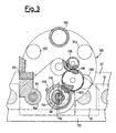
- Fig. 3 is a view along line 3-3 of Fig. 2 of the unitary mould and conveyor disc assembly of the present invention.
- Referring to the drawings and in particular to Fig. 1 the machine in accordance with the invention comprises a
conveyor chain 10 the links of which are formed ofcup devices 12 better illustrated in Fig. 2. The conveyor chain is driven by adrive roller 14 in the direction of thearrow 16 and closes on anidling roller 18. - The operating travel of the
chain 10 takes place on the supporting table shown schematically in Fig. 1 with thenumber 22. For the sake of brevity, a detailed description thereof is omitted except as specifically pertains ot the cup devices and the other features forming the object of the present invention. Above theconveyor chain 10 is mounted aframe 24 presenting twouprights cam shaft 30 driven by a reducinggear 32 and bearing a plurality ofcams -
Number 42 indicates a roll of filter-paper ribbon mounted in a rotating manner on a paper-holding reel 44 which is born by abracket 46. From theroll 42 is taken, the filter-paper ribbon 48, designed to form the lower or supporting ribbon of the strip of filter pockets or bags indicated generally bynumber 50 at the right end of Fig. 1, eachpocket 50 comprising a cavity formed by said lower filter-paper ribbon 48, an upper or closing filter-paper ribbon 52 and a tablet measure offresh coffee powder 54. - The filter-
paper ribbon 52 is taken from aroll 56 mounted in a freely rotating manner on a reel ormandrel 58 born by asupport 60. Now considering all the figures, it is seen that on thecrosspiece 62 of theframe 24 there are mounted in order (1) aunitary mould 64 the purpose of which is to preform and fill with coffee powder the lower filter-paper ribbon, (2) a forming and sealingmember 140 having the purpose of shaping and sealing theupper ribbon 52 of filter paper to thelower ribbon 48 to form apocket 50. - The
unitary mould 64 is formed of a base plate or sole 66, ahole 70 for passage of measures ofcoffee powder 72, and atamper 74 with an overturned cup, said tamper being supported by ashaft 76, by acover 78, by twostems motion transmission mechanism stems cams - The
tamper 74 mounted on the rotatingshaft 76 is driven in its reciprocating movement by astem 88 equipped with aside protuberance 90 designed to engage with ashaped groove 92 made in thecam 36 in such a manner as to permit positive engagement of said cam with thestem 88 in both directions of its reciprocating movement. Saidstem 88 is fitted in a sliding manner in asheath 94 fixed to thecross piece 62 and is fitted in its lower part with a thrust bearing 96 designed to connect saidstem 88 with the rotatingshaf 76 in such as a manner as to permit it free rotation and reciprocating movement conferred by thestem 88. Theshaft 76 hasgrooves 98 which permit axially sliding engagement with asprocket 100 which is driven in turn by a gear assembly which be explained in greater detail here below. - The
sprocket 100 is housed in a seat formed by anupper flange 102 and alower flange 104 which is in turn fixed to acylindrical casing 106 bearing inside areel 108 and forming a rotatingdistribution valve assembly 110 having the purpose which will be explained here below. Thecover 78 of theunitary mould 64 contains a member for conveyance of the coffee powder measures formed by adisc 120 traversed by the openings 122,124,126 designed to receive one measure of freshly ground coffee each coming from adelivery system 130 connected to known grinding means such as the means 132 shown in outline in Fig. 1. - The
disc 120 is integral with a shaft pivoted in thebase plate sole 66 and in thecover 78 of theunitary mould 64 and moves in steps covering angles corresponding to the distance between two adjoining openings in the disc in such a manner as to permit stopping and alignment of said openings with thesystem 130 which delivers coffee and with thehole 70 in thebase plate 66 respectively to permit passage of the ground coffee first from thedelivery system 130 to the openings in the disc and then from the openings in the disc to thehole 70 in thebase plate 66 for the purpose of depositing said measure of coffee on the filter-paper ribbon 48 supported on acup device 12. - The opening in the
disc 120, as the opening 128, which at that moment is aligned with thehole 70 and with thetamper 74, is traversed by said tamper which pushes and tamps all the coffee powder on theribbon 48. Subsequently thetamper 74 withdraws and frees theopening 128 of thedisc 120 which can thus rotate to a subsequent position. - The
chain 10 in its step movement following the direction indicated by thearrows 16 brings thelower ribbon 48 with the measure of tamped coffee out of theunitary mould 64 to meet an upper coveringribbon 52, also of filter paper, which is superimposed on thelower ribbon 48 and is sealed therewith by a forming and sealingmember 140 made up of a flat plate having tray- like recesses similar to those of thecup device 12 and heated in the conventional manner to permit the thermosealing of the two filter-paper ribbons, said forming and sealing member being of the type known in the prior art. - The forming and sealing
member 140 is fixed to astem 142 which, through amotion transmission mechanism 144 fixed to thecrosspiece 62, rests on thecam 40 receiving therefrom a reciprocating movement which causes themember 140 to rotate between its lower position, represented in solid lines, and anupper position 140a represented in broken lines. - Following this forming and thermosealing station, the paper ribbon bearing the filled
pockets 50 moves to subsequent stations for punching of holes or perforation of weakening zones to aid tearing as well as shearing of the individual pockets for preparation thereof in the package forms required by the market. - A particularly interesting feature of the present invention is provided by the support table 22 on which slides the
chain 10 bearing thecup devices 12 beneath theunitary mould 64 and beneath the forming and sealingmember 140. Said support table 22 is fitted underneath withducts 148 communicating with acover 150 divided in twocompartments partition 156 and communicating with the two respective sources of vacuum of which the one connected with thecompartment 152 operates intermittently and the one connected with thecompartment 154 operates continuously. Thecompartments 152 are connected to a general source of vacuum through aduct 158 which, through apipe 162, passes through thedistribution valve 110 which permits vacuum only at certain times, while thecompartment 154 is connected permanently through aduct 160 to said general vacuum source. - Returning for a moment to the
distribution valve 110 illustrated in Figs. 2 and 3 and observing in particular Fig. 3 it is seen that said valve is formed of acylindrical reel 108 rotating by means of the action of theshaft 76 within thecylindrical casing 106 with smooth interior walls which form a seal withsaid reel 108. Said reel has protuberances orlands 112 and lowerings or recesses, such as therecess 114, which permit intermittent communication linked with a portion of theshaft 76, between aduct 170 connected with the general vacuum source and theabovesaid pipe 162 in such a manner as to apply to thecompartments 152 an intermittent vacuum linked with the rotation of saidshaft 76. This fact prevents the presence of vacuum when the coffee powder passes from theopening 128 of thedisc 120 through thehole 70 of theunitary mould 64 on thelower ribbon 48 of filter paper since vacuum at this moment could cause dispersal and uneven tamping of the coffee powder. Since the action of thedistribution valve 110 is linked to the position of thedisc 120, thegear 100 is connected through anintermediate gear 116 to adrive gear 118 which provides synchronous movement of saiddisc 120 and of theshaft 76. Summarizing the operation of the present invention, to form thepockets 50 of coffee powder or the like, afilter paper ribbon 48 is laid on thecup devices 12 ofchain 10 which advances in steps under themould 64 and under the forming and sealingmember 140. - In the first position the
ribbon 48 is preformed by the vacuum of the bottom of the depressions any by theprotuberance 68. - In the second position, the preshaped ribbon is loaded with a measure of
coffee powder 72 which is subsequently packed by thetamper 74 with overturned cup which evens completely said measure of coffee. During filling of the powder the vacuum is stopped by thedistribution valve 110 to avoid dispersal and uneven tamping of said powder. - In subsequent positions the
ribbon 48, bearing the load of coffee powder, is covered by theupper ribbon 52 which is subsequently welded to thelower ribbon 48 by the forming and sealingmember 140 obtaining thereby thepocket 50. - In subsequent position the completed ribbon containing the
pockets 50 is provided with punched side holes and/or weakening perforations to permit their use and the formation of packages desired by market. - The invention has been described for a machine for the preparation of strips of pockets for fresh coffee powder but only as an example, because the machine may be used in an essentially similar manner for the preparation of filter bags of other infusion substances such as tea, chamomile, and the like.
Claims (4)
Priority Applications (1)
| Application Number | Priority Date | Filing Date | Title |
|---|---|---|---|
| AT86115564T ATE60744T1 (en) | 1985-11-11 | 1986-11-10 | MACHINE FOR MAKING PAPER BAGS CONTAINING A SUBSTANCE FOR PREPARING AN INFUSION OR AN INFUSION BEVERAGE (LIKE COFFEE OR TEA). |
Applications Claiming Priority (2)
| Application Number | Priority Date | Filing Date | Title |
|---|---|---|---|
| IT2378485U | 1985-11-11 | ||
| IT8523784U IT8523784V0 (en) | 1985-11-11 | 1985-11-11 | PERFECTED MACHINE FOR FILTER PAPER PODS FOR THE PREPARATION OF INFUSIONS. |
Publications (2)
| Publication Number | Publication Date |
|---|---|
| EP0225494A1 EP0225494A1 (en) | 1987-06-16 |
| EP0225494B1 true EP0225494B1 (en) | 1991-02-06 |
Family
ID=11209967
Family Applications (1)
| Application Number | Title | Priority Date | Filing Date |
|---|---|---|---|
| EP86115564A Expired - Lifetime EP0225494B1 (en) | 1985-11-11 | 1986-11-10 | Improved machine manufacturing paper bags containing some substance to prepare infusions or infused beverages (as coffee or tea) |
Country Status (7)
| Country | Link |
|---|---|
| US (1) | US4747250A (en) |
| EP (1) | EP0225494B1 (en) |
| AT (1) | ATE60744T1 (en) |
| AU (1) | AU583954B2 (en) |
| DE (1) | DE3677475D1 (en) |
| ES (1) | ES2019869B3 (en) |
| IT (1) | IT8523784V0 (en) |
Cited By (2)
| Publication number | Priority date | Publication date | Assignee | Title |
|---|---|---|---|---|
| US10702894B2 (en) | 2016-06-24 | 2020-07-07 | The Procter & Gamble Company | Seal cleaner and process for soluble unit dose pouches containing granular composition |
| EP4640568A3 (en) * | 2024-04-25 | 2025-11-05 | Syntegon Technology GmbH | Method for producing a plurality of packages |
Families Citing this family (32)
| Publication number | Priority date | Publication date | Assignee | Title |
|---|---|---|---|---|
| IT1213385B (en) * | 1986-11-25 | 1989-12-20 | Illycaffe Spa | METHOD TO PRODUCE A GROUND COFFEE DISCOID TO EXTRACT AN EXPRESS COFFEE. |
| US5459980A (en) * | 1989-04-28 | 1995-10-24 | A.G. (Patents) Limited | Manufacturing infusion packages |
| US5233813A (en) * | 1989-04-28 | 1993-08-10 | Ag (Patents) Limited | Manufacturing infusion packages |
| US5074102A (en) * | 1989-10-26 | 1991-12-24 | American Cyanamid Company | Flat track modified soft shell capsule filling machine |
| US5081819A (en) * | 1989-12-04 | 1992-01-21 | Cloud Corporation | Method and apparatus for manufacture and packaging of filter packs for use in a brew basket |
| EP0765604B1 (en) * | 1995-09-27 | 2000-11-08 | Teepack Spezialmaschinen Gmbh & Co. Kg | Process and apparatus for flavouring tea and similar products |
| IT237277Y1 (en) * | 1995-11-10 | 2000-09-05 | Rossi S R L G | PERFECTED EQUIPMENT FOR THE MANUFACTURE OF COFFEE DUSTING PODS |
| IT1277108B1 (en) * | 1995-12-19 | 1997-11-04 | Opem Srl | MACHINE FOR PRODUCING, FROM CONTINUOUS FILM, ROUND AND NON-ROUND COFFEE PODS FOR AUTOMATIC ESPRESSO COFFEE MACHINES |
| IT1299927B1 (en) * | 1998-03-20 | 2000-04-04 | Dima Srl | PREFORMING DEVICE FOR MACHINES FOR THE PRODUCTION AND PACKAGING OF INFUSION PRODUCT PODS. |
| FR2800709B1 (en) | 1999-11-09 | 2001-12-14 | Cie Mediterraneenne Des Cafes | INSTALLATION AND METHOD FOR MANUFACTURING SINGLE PODS FOR INFUSION |
| US6758130B2 (en) | 2001-03-16 | 2004-07-06 | The Procter + Gamble Co. | Beverage brewing devices for preparing creamy beverages |
| ITBO20030475A1 (en) * | 2003-08-01 | 2005-02-02 | Roberto Conti | DEVICE FOR DOSING AND FORMING PODS FOR INFUSION PRODUCTS. |
| ITBO20030474A1 (en) * | 2003-08-01 | 2005-02-02 | Roberto Conti | METHOD AND EQUIPMENT FOR THE PRODUCTION OF PODS FOR INFUSION PRODUCTS. |
| ITBO20030666A1 (en) * | 2003-11-12 | 2005-05-13 | Aroma System S R L | PODS PACKAGING MACHINE IN PAPER FILTER. |
| US7213699B2 (en) * | 2004-03-24 | 2007-05-08 | Adams Edward E | Rotary disc conveyor system |
| ITBO20040363A1 (en) * | 2004-06-08 | 2004-09-08 | Aroma System Srl | COMBINED DEVICE TO FEED AND COMPACT PREDETERMINED DOSES OF GROUND COFFEE OR OTHER SIMILAR SUBSTANCES |
| ITBO20040442A1 (en) * | 2004-07-16 | 2004-10-16 | Roberto Conti | UNIT FOR THE SUPPLY OF MATERIAL FROM INFUSION TO A MACHINE PRODUCING PACKAGES IN FILTER MATERIAL |
| ITBO20040548A1 (en) * | 2004-09-07 | 2004-12-07 | Goglio Spa | MACHINE FOR MAKING PACKAGES OF INFUSION PRODUCTS |
| RU2413420C2 (en) * | 2006-01-13 | 2011-03-10 | БЕЛЛОЛИ Джанпаоло | Product prepared from powder-like or granulated material, and method of its production |
| ITBO20070196A1 (en) * | 2007-03-20 | 2008-09-21 | Azionaria Costruzioni Acma Spa | MACHINE AND METHOD FOR THE PRODUCTION OF BAGS OF UNCONTROL MATERIAL. |
| EP2170282A4 (en) * | 2007-06-27 | 2014-11-05 | Hanmi Pharm Ind Co Ltd | METHOD FOR PREPARING RAPID DISAGGREGATION FORMULATION FOR ORAL ADMINISTRATION AND APPARATUS FOR PREPARING AND PACKAGING THEREFOR |
| CN104757223B (en) | 2009-04-09 | 2019-12-10 | 福尔杰咖啡公司 | Coffee tablet and preparation method thereof |
| US20120015094A1 (en) | 2009-04-09 | 2012-01-19 | The Folgers Coffee Company | Ground roast coffee tablet |
| DE102010013889A1 (en) * | 2010-04-07 | 2011-10-13 | Multivac Sepp Haggenmüller Gmbh & Co. Kg | Device for chamber belt machine |
| IT1400204B1 (en) * | 2010-05-31 | 2013-05-24 | Rent Srl | EQUIPMENT AND METHOD FOR PACKAGING WITH PLASTIC BATTERY FILM OF PAPER BENDED PRODUCTS SUCH AS HANDKERCHARMS OR SIMILAR |
| US9156573B2 (en) * | 2011-03-30 | 2015-10-13 | Alkar-Rapidpak, Inc. | Packaging apparatuses and methods |
| CN102700062A (en) * | 2012-05-10 | 2012-10-03 | 太仓戴尔塔精密模具有限公司 | Die for Teflon ribbon |
| ES2675030T3 (en) * | 2014-07-08 | 2018-07-05 | Gima S.P.A. | Unit and method for filling single-use capsule container elements for extraction or infusion drinks |
| CN104691824A (en) * | 2015-02-15 | 2015-06-10 | 桐乡市绿康菊业有限公司 | Special quantitative conveying device for chrysanthemum bud tea bag packing machine |
| ITUB20152469A1 (en) * | 2015-07-24 | 2017-01-24 | Marco Verri | EQUIPMENT FOR THE PRODUCTION OF A PRODUCT, PREFERABLY OF A FOOD PRODUCT TO REALIZE A DRINK THROUGH INFUSION IN A LIQUID RESPECTIVE |
| IT201700049857A1 (en) * | 2017-05-09 | 2018-11-09 | Opem S P A | EQUIPMENT AND METHOD FOR THE MANUFACTURE OF PODS FOR DRINKS |
| CN112810858B (en) * | 2021-01-05 | 2022-09-09 | 青海瑞恒堂生态农业有限公司 | Quantitative filling device is used in beverage processing |
Family Cites Families (11)
| Publication number | Priority date | Publication date | Assignee | Title |
|---|---|---|---|---|
| US3045404A (en) * | 1961-01-26 | 1962-07-24 | Forgrove Mach | Wrapping machines |
| GB1011872A (en) * | 1961-05-26 | 1965-12-01 | Melikian Inc Rudd | Packaging of material in pockets formed between tape strips |
| US3186141A (en) * | 1961-06-01 | 1965-06-01 | Melikian Inc Rudd | Apparatus for production of tapes having spaced package pockets |
| US3218776A (en) * | 1961-09-11 | 1965-11-23 | Cloud Machine Corp | Packaging method and apparatus |
| FR1444527A (en) * | 1965-08-13 | 1966-07-01 | J S Petzhold Inh Herbert Pilz | Machine for wrapping articles of irregular shapes, in particular chocolate hollow bodies |
| US3481283A (en) * | 1966-09-20 | 1969-12-02 | Clarence W Vogt | Package forming and filling apparatus |
| US4048785A (en) * | 1976-07-19 | 1977-09-20 | Baker Perkins Holdings Limited | Apparatus for depositing fibrous material into containers |
| DE2930963C2 (en) * | 1979-07-31 | 1984-01-12 | Krämer & Grebe GmbH & Co KG Maschinen- und Modellfabrik, 3560 Biedenkopf | Packaging device |
| IT1133279B (en) * | 1980-04-17 | 1986-07-09 | Ima Spa | VOLUMETRIC DOSER FOR INCONERENT PRODUCTS, PARTICULARLY SUITABLE FOR FAST PACKAGING MACHINES-FILTER BAGS FOR INFUSION PRODUCTS SUCH AS YOU, CHAMOMILE AND SIMILAR |
| US4594066A (en) * | 1984-06-25 | 1986-06-10 | Carruthers Equipment Co. | Pressure relief apparatus |
| US4571924A (en) * | 1985-04-29 | 1986-02-25 | The Procter & Gamble Company | Method and apparatus of manufacturing porous pouches containing granular product |
-
1985
- 1985-11-11 IT IT8523784U patent/IT8523784V0/en unknown
-
1986
- 1986-11-10 EP EP86115564A patent/EP0225494B1/en not_active Expired - Lifetime
- 1986-11-10 US US06/929,680 patent/US4747250A/en not_active Expired - Fee Related
- 1986-11-10 AT AT86115564T patent/ATE60744T1/en not_active IP Right Cessation
- 1986-11-10 DE DE8686115564T patent/DE3677475D1/en not_active Expired - Lifetime
- 1986-11-10 ES ES86115564T patent/ES2019869B3/en not_active Expired - Lifetime
- 1986-11-11 AU AU64992/86A patent/AU583954B2/en not_active Ceased
Cited By (2)
| Publication number | Priority date | Publication date | Assignee | Title |
|---|---|---|---|---|
| US10702894B2 (en) | 2016-06-24 | 2020-07-07 | The Procter & Gamble Company | Seal cleaner and process for soluble unit dose pouches containing granular composition |
| EP4640568A3 (en) * | 2024-04-25 | 2025-11-05 | Syntegon Technology GmbH | Method for producing a plurality of packages |
Also Published As
| Publication number | Publication date |
|---|---|
| IT8523784V0 (en) | 1985-11-11 |
| ES2019869B3 (en) | 1991-07-16 |
| EP0225494A1 (en) | 1987-06-16 |
| US4747250A (en) | 1988-05-31 |
| DE3677475D1 (en) | 1991-03-14 |
| ATE60744T1 (en) | 1991-02-15 |
| AU6499286A (en) | 1987-06-25 |
| AU583954B2 (en) | 1989-05-11 |
Similar Documents
| Publication | Publication Date | Title |
|---|---|---|
| US4747250A (en) | Machine manufacturing paper bags containing some substance to prepare infusions or infused beverages | |
| TWI327122B (en) | Device for dosing and forming pods for products for infusion | |
| EP0773160B1 (en) | Apparatus for the manufacture of bags containing ground coffee powder | |
| CA2031502C (en) | Manufacturing infusion packages | |
| EP1648776B1 (en) | Method and apparatus for making pods for products for infusion | |
| JP3293841B2 (en) | Equipment for manufacturing bag-shaped packs for chewing tobacco | |
| US6212859B1 (en) | Packaging machine with rotary top sealer | |
| US5459980A (en) | Manufacturing infusion packages | |
| US3736722A (en) | Packaging machine | |
| US5233813A (en) | Manufacturing infusion packages | |
| US5549144A (en) | Compression filler for aerateable powders | |
| CS200472B2 (en) | Facility for transportation and shaping the insert dimension goods | |
| EP2207718B1 (en) | Machine for making pods containing infusion products | |
| US3691718A (en) | Pouch forming apparatus and method | |
| JP2023536308A (en) | Devices and manufacturing processes for infusion capsules | |
| EP1689644B1 (en) | Apparatus for making pods for infusion products | |
| CN202879810U (en) | High-speed full-automatic packing machine | |
| US3186137A (en) | Method and apparatus for the production of beverage type | |
| US4012889A (en) | Packaging machine | |
| JP2595200B2 (en) | Automatic packaging machine | |
| EP1038777B1 (en) | A device for compacting and holding a loose solid substance, dosed at regular intervals, on a mobile conveyor belt which is permeable to air | |
| JPS6042082B2 (en) | Filling equipment for thin individual bags | |
| ITBO950584A1 (en) | MACHINE FOR THE PRODUCTION AND PACKAGING OF INFUSION PRODUCT PODS |
Legal Events
| Date | Code | Title | Description |
|---|---|---|---|
| PUAI | Public reference made under article 153(3) epc to a published international application that has entered the european phase |
Free format text: ORIGINAL CODE: 0009012 |
|
| AK | Designated contracting states |
Kind code of ref document: A1 Designated state(s): AT BE CH DE ES FR GB GR IT LI LU NL SE |
|
| 17P | Request for examination filed |
Effective date: 19871204 |
|
| 17Q | First examination report despatched |
Effective date: 19890224 |
|
| GRAA | (expected) grant |
Free format text: ORIGINAL CODE: 0009210 |
|
| AK | Designated contracting states |
Kind code of ref document: B1 Designated state(s): AT BE CH DE ES FR GB GR IT LI LU NL SE |
|
| PG25 | Lapsed in a contracting state [announced via postgrant information from national office to epo] |
Ref country code: GR Free format text: LAPSE BECAUSE OF FAILURE TO SUBMIT A TRANSLATION OF THE DESCRIPTION OR TO PAY THE FEE WITHIN THE PRESCRIBED TIME-LIMIT Effective date: 19910206 |
|
| REF | Corresponds to: |
Ref document number: 60744 Country of ref document: AT Date of ref document: 19910215 Kind code of ref document: T |
|
| REF | Corresponds to: |
Ref document number: 3677475 Country of ref document: DE Date of ref document: 19910314 |
|
| ITF | It: translation for a ep patent filed | ||
| ET | Fr: translation filed | ||
| PLBE | No opposition filed within time limit |
Free format text: ORIGINAL CODE: 0009261 |
|
| STAA | Information on the status of an ep patent application or granted ep patent |
Free format text: STATUS: NO OPPOSITION FILED WITHIN TIME LIMIT |
|
| 26N | No opposition filed | ||
| EPTA | Lu: last paid annual fee | ||
| EAL | Se: european patent in force in sweden |
Ref document number: 86115564.6 |
|
| REG | Reference to a national code |
Ref country code: CH Ref legal event code: PUE Owner name: LUIGI ROSSI TRANSFER- ROSSI GIAMPIERO Ref country code: CH Ref legal event code: NV Representative=s name: PATENTANWAELTE SCHAAD, BALASS, MENZL & PARTNER AG |
|
| PGFP | Annual fee paid to national office [announced via postgrant information from national office to epo] |
Ref country code: FR Payment date: 19961028 Year of fee payment: 11 |
|
| PGFP | Annual fee paid to national office [announced via postgrant information from national office to epo] |
Ref country code: AT Payment date: 19961029 Year of fee payment: 11 |
|
| PGFP | Annual fee paid to national office [announced via postgrant information from national office to epo] |
Ref country code: LU Payment date: 19961101 Year of fee payment: 11 Ref country code: GB Payment date: 19961101 Year of fee payment: 11 |
|
| PGFP | Annual fee paid to national office [announced via postgrant information from national office to epo] |
Ref country code: SE Payment date: 19961104 Year of fee payment: 11 |
|
| PGFP | Annual fee paid to national office [announced via postgrant information from national office to epo] |
Ref country code: ES Payment date: 19961108 Year of fee payment: 11 |
|
| PGFP | Annual fee paid to national office [announced via postgrant information from national office to epo] |
Ref country code: BE Payment date: 19961114 Year of fee payment: 11 |
|
| PGFP | Annual fee paid to national office [announced via postgrant information from national office to epo] |
Ref country code: CH Payment date: 19961126 Year of fee payment: 11 |
|
| PGFP | Annual fee paid to national office [announced via postgrant information from national office to epo] |
Ref country code: NL Payment date: 19961129 Year of fee payment: 11 Ref country code: DE Payment date: 19961129 Year of fee payment: 11 |
|
| NLS | Nl: assignments of ep-patents |
Owner name: GIAMPIERO ROSSI |
|
| REG | Reference to a national code |
Ref country code: FR Ref legal event code: TP |
|
| REG | Reference to a national code |
Ref country code: ES Ref legal event code: PC2A Owner name: GIAMPIERO ROSSI |
|
| PG25 | Lapsed in a contracting state [announced via postgrant information from national office to epo] |
Ref country code: LU Free format text: LAPSE BECAUSE OF NON-PAYMENT OF DUE FEES Effective date: 19971110 Ref country code: GB Free format text: LAPSE BECAUSE OF NON-PAYMENT OF DUE FEES Effective date: 19971110 Ref country code: AT Free format text: LAPSE BECAUSE OF NON-PAYMENT OF DUE FEES Effective date: 19971110 |
|
| PG25 | Lapsed in a contracting state [announced via postgrant information from national office to epo] |
Ref country code: SE Free format text: LAPSE BECAUSE OF NON-PAYMENT OF DUE FEES Effective date: 19971111 Ref country code: ES Free format text: LAPSE BECAUSE OF NON-PAYMENT OF DUE FEES Effective date: 19971111 |
|
| PG25 | Lapsed in a contracting state [announced via postgrant information from national office to epo] |
Ref country code: LI Free format text: LAPSE BECAUSE OF NON-PAYMENT OF DUE FEES Effective date: 19971130 Ref country code: FR Free format text: THE PATENT HAS BEEN ANNULLED BY A DECISION OF A NATIONAL AUTHORITY Effective date: 19971130 Ref country code: CH Free format text: LAPSE BECAUSE OF NON-PAYMENT OF DUE FEES Effective date: 19971130 Ref country code: BE Free format text: LAPSE BECAUSE OF NON-PAYMENT OF DUE FEES Effective date: 19971130 |
|
| BERE | Be: lapsed |
Owner name: ROSSI GIAMPIERO Effective date: 19971130 |
|
| PG25 | Lapsed in a contracting state [announced via postgrant information from national office to epo] |
Ref country code: NL Free format text: LAPSE BECAUSE OF NON-PAYMENT OF DUE FEES Effective date: 19980601 |
|
| GBPC | Gb: european patent ceased through non-payment of renewal fee |
Effective date: 19971110 |
|
| REG | Reference to a national code |
Ref country code: CH Ref legal event code: PL |
|
| PG25 | Lapsed in a contracting state [announced via postgrant information from national office to epo] |
Ref country code: DE Free format text: LAPSE BECAUSE OF NON-PAYMENT OF DUE FEES Effective date: 19980801 |
|
| EUG | Se: european patent has lapsed |
Ref document number: 86115564.6 |
|
| NLV4 | Nl: lapsed or anulled due to non-payment of the annual fee |
Effective date: 19980601 |
|
| REG | Reference to a national code |
Ref country code: FR Ref legal event code: ST |
|
| REG | Reference to a national code |
Ref country code: ES Ref legal event code: FD2A Effective date: 19981212 |
|
| PGFP | Annual fee paid to national office [announced via postgrant information from national office to epo] |
Ref country code: IT Payment date: 20051124 Year of fee payment: 20 |