EP0225428A2 - Method for the recognition of edge structures in a picture signal - Google Patents
Method for the recognition of edge structures in a picture signal Download PDFInfo
- Publication number
- EP0225428A2 EP0225428A2 EP86110641A EP86110641A EP0225428A2 EP 0225428 A2 EP0225428 A2 EP 0225428A2 EP 86110641 A EP86110641 A EP 86110641A EP 86110641 A EP86110641 A EP 86110641A EP 0225428 A2 EP0225428 A2 EP 0225428A2
- Authority
- EP
- European Patent Office
- Prior art keywords
- edge
- pixel
- points
- orientation
- image
- Prior art date
- Legal status (The legal status is an assumption and is not a legal conclusion. Google has not performed a legal analysis and makes no representation as to the accuracy of the status listed.)
- Granted
Links
Images

Classifications
-
- H—ELECTRICITY
- H04—ELECTRIC COMMUNICATION TECHNIQUE
- H04N—PICTORIAL COMMUNICATION, e.g. TELEVISION
- H04N1/00—Scanning, transmission or reproduction of documents or the like, e.g. facsimile transmission; Details thereof
- H04N1/40—Picture signal circuits
- H04N1/409—Edge or detail enhancement; Noise or error suppression
- H04N1/4092—Edge or detail enhancement
-
- G—PHYSICS
- G06—COMPUTING; CALCULATING OR COUNTING
- G06T—IMAGE DATA PROCESSING OR GENERATION, IN GENERAL
- G06T7/00—Image analysis
- G06T7/10—Segmentation; Edge detection
- G06T7/12—Edge-based segmentation
-
- G—PHYSICS
- G06—COMPUTING; CALCULATING OR COUNTING
- G06T—IMAGE DATA PROCESSING OR GENERATION, IN GENERAL
- G06T9/00—Image coding
- G06T9/001—Model-based coding, e.g. wire frame
-
- G—PHYSICS
- G06—COMPUTING; CALCULATING OR COUNTING
- G06T—IMAGE DATA PROCESSING OR GENERATION, IN GENERAL
- G06T2207/00—Indexing scheme for image analysis or image enhancement
- G06T2207/10—Image acquisition modality
- G06T2207/10016—Video; Image sequence
Definitions
- the invention relates to a method for recognizing edge structures in an image signal, a decision criterion being obtained from the surroundings of an image point in order to achieve coding with the smallest possible number of bits.
- the invention has for its object to provide a method for the detection of edge structures in an image signal, which is particularly suitable for edges with an orientation that are not horizontal, vertical or at 45 ° to the horizontal, with less effort than before was possible to recognize, the method should be suitable for processing still images.
- n windows each consisting of one pixel Bp with its surrounding points Up are written into a shift register (see FIG. 1).
- the number n of windows stored essentially depends on the processing time of the subsequent mean value generator, because after the formation of the first mean value, the inscribed image point and the associated environmental points have been moved forward by n cycles.
- the corresponding environmental points Up 1 + n , ... Up 19 + n which have now been moved by n storage locations, are used.
- edge block decoder If several edge points have been recognized in the edge point decoder, a decision is made in the subsequent edge block decoder as to whether or not the entire partial image area is to be coded as an edge block. The edge block decoder then gives a log accordingly. 1 or a log. 0 at its output in order to influence an image coding algorithm.
- the main advantages of the method according to the invention lie in the independence of the edge detection from the response threshold, the simple technical feasibility of the method and the reliable selection capability of the edge orientation, in particular also for oblique edges.
Abstract
Die Erfindung betrifft ein Verfahren zur Erkennung von Kantenstrukturen in einem Bildsignal, wobei aus den Umgebungspunkten eines Bildpunktes ein Entscheidungskriterium gewonnen wird, um eine Kodierung mit möglichst geringer Bitzahl zu erreichen.
Die Aufgabe vor allem bei Standbildern auch schiefliegende Kanten, d.h. Kanten, die nicht horizontal, vertikal oder diagonal liegen, zu erkennen wird dadurch gelöst, daß aus den Umgebungspunkten eines Bildpunktes ein Mittelwert gebildet wird, der dann mit jedem Umgebungspunkt verglichen wird, um ein dreiwertiges (1, 0, -1) Signal zu gewinnen. Aus der Anzahl der unmittelbar aufeinanderfolgenden gleichartigen Wertigkeiten (1, oder -1) dieses dreiwertigen Signales und der Lage der Wertigkeitenwechsel innerhalb der Umgebungspunkte wird auf eine Kante und deren Orientierung geschlossen (Fig. 1, 2). 

The task, especially in still images, to recognize skewed edges, ie edges that are not horizontal, vertical or diagonal, is achieved by forming an average value from the surrounding points of a pixel, which is then compared with each surrounding point by a trivalent value (1, 0, -1) signal to win. An edge and its orientation are inferred from the number of immediately consecutive valences of the same kind (1 or -1) of this trivalent signal and the position of the valency changes within the surrounding points (FIGS. 1, 2).
Description
Die Erfindung betrifft ein Verfahren zur Erkennung von Kantenstrukturen in einem Bildsignal, wobei aus der Umgebung eines Bildpunktes ein Entscheidungskriterium gewonnen wird, um eine Kodierung mit möglichst geringer Bitzahl zu erreichen.The invention relates to a method for recognizing edge structures in an image signal, a decision criterion being obtained from the surroundings of an image point in order to achieve coding with the smallest possible number of bits.
Solche Verfahren sind bereits bekannt, z.B. aus dem Buch "Digital Image Processing" von William K. Pratt, A. Wiley-Interscience Publication; John Wiley & Sons, New York, Chichester, Brisbane, Toronto, 1978 Capter 17: "Image feature Extraction", Seiten 471 bis 499. Hier werden verschiedene Verfahren vorgestellt und miteinander verglichen, mit denen Kantenstrukturen in einem Bildsignal erkannt werden können. Die Unterscheidungsfähigkeit zwischen Strukturen und Nichtstrukturen ist bei den verschiedenen Verfahren recht gut und der Realisierungsaufwand z.B. in Bezug auf die Anzahl der Multiplikationen unterschiedlich. Jedoch ist die Orientierung der Kanten mit den bekannten Verfahren nur schwer zu erkennen, insbesondere sind Orientierungen die nicht horizontal, vertikal oder unter 45° zur Horizontalen verlaufen nicht erkennbar. Außerdem sind die bekannten Verfahren sehr empfindlich in Bezug auf die Festlegung ihrer Ansprechschwelle.Such methods are already known, e.g. from the book "Digital Image Processing" by William K. Pratt, A. Wiley-Interscience Publication; John Wiley & Sons, New York, Chichester, Brisbane, Toronto, 1978 Capter 17: "Image feature Extraction", pages 471 to 499. Here various methods are presented and compared with one another with which edge structures can be recognized in an image signal. The differentiation between structures and non-structures is quite good with the different processes and the implementation effort e.g. different in terms of the number of multiplications. However, the orientation of the edges is difficult to recognize with the known methods, in particular orientations that are not horizontal, vertical or at 45 ° to the horizontal cannot be recognized. In addition, the known methods are very sensitive to the setting of their response threshold.
Der Erfindung liegt die Aufgabe zugrunde, ein Verfahren zur Erkennung von Kantenstrukturen in einem Bildsignal anzugeben, das vor allem dazu geeignet ist, Kanten mit einer Orientierung die nicht horizontal, vertiakl oder unter 45° zur Horizontalen ausgeprägt sind, mit einem geringeren Aufwand als es bisher möglich war zu erkennen, dabei soll das Verfahren für die Verarbeitung von Standbildern geeignet sein.The invention has for its object to provide a method for the detection of edge structures in an image signal, which is particularly suitable for edges with an orientation that are not horizontal, vertical or at 45 ° to the horizontal, with less effort than before was possible to recognize, the method should be suitable for processing still images.
Die Aufgabe wird gelöst, wie im Kennzeichen des Anspruchs 1 beschrieben. Die Unteransprüche geben vorteilhafte Ausbildungen an.The object is achieved as described in the characterizing part of claim 1. The sub-claims indicate advantageous training.
Im folgenden sei die Erfindung anhand von einem Ausführungsbeispiel mit Hilfe von Figuren näher erläutert.
- Fig. 1 zeigt ein Blockschaltbild zur Realisierung des erfindungsgemäßen Verfahrens.
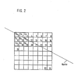
- Fig. 2 zeigt einen Teilbildbereich der 64 Bildpunkte umfaßt mit einer schief verlaufenden Kante, dabei bedeutet Bp = Bildpunkt, Up = Umgebungspunkt.
- 1 shows a block diagram for implementing the method according to the invention.
- FIG. 2 shows a partial image area comprising 64 pixels with an obliquely running edge, where Bp = pixel, Up = surrounding point.
Das gesamte Standbild wird in Teilbildbereiche eingeteilt. Aus dem Teilbildbereich werden jeweils n Fenster bestehend aus jeweils einem Bildpunkt Bp mit seinen Umgebungspunkten Up in einem Schieberegister eingeschrieben (siehe dazu Fig. 1). Die Anzahl n der gespeicherten Fenster hängt im wesentlichen von der Verarbeitungszeit des nachfolgenden Mittelwertbildners ab, denn nach der Bildung des ersten Mittelwertes ist inzwischen der eingeschriebene Bildpunkt und die zugehörigen Umgebungspunkte um n Takte weitergeschoben worden. Zu dem sich anschließenden Vergleich des Mittelwertes mit den dazugehörigen Umgebungspunkten, werden die entsprechenden inzwischen um n Speicherplätze weitergeschobenen Umgebungspunkte Up1+n, ... Up19+n herangezogen.The entire still image is divided into partial image areas. From the partial image area, n windows each consisting of one pixel Bp with its surrounding points Up are written into a shift register (see FIG. 1). The number n of windows stored essentially depends on the processing time of the subsequent mean value generator, because after the formation of the first mean value, the inscribed image point and the associated environmental points have been moved forward by n cycles. For the subsequent comparison of the mean value with the associated environmental points, the corresponding environmental points Up 1 + n , ... Up 19 + n , which have now been moved by n storage locations, are used.
Aus dem Vergleich ergeben sich die dreiwertigen (1, 0, -1) Signale (S₀ ... S₇).The comparison gives the trivalent (1, 0, -1) signals (S₀ ... S₇).
Diese dreiwertigen Signale werden zwischengespeichert in dem Dekoderregister und zur weiteren Verarbeitung im Kantenpunkt-Dekoder bereitgestellt.These three-valued signals are buffered in the decoder register and made available for further processing in the edge point decoder.
Im Kantenpunkt-Dekoder wird nun entschieden, ob der betref fende Bildpunkt ein Kantenpunkt ist oder nicht und zwar nach der Vorschrift des Anspruchs 2 oder 3.It is now decided in the edge point decoder whether it concerns fende pixel is an edge point or not and that according to the provision of
Sind im Kantenpunkt-Dekoder mehrere Kantenpunkte erkannt worden, so wird im nachfolgenden Kantenblock-Dekoder entschieden, ob der ganze Teilbildbereich als ein Kantenblock kodiert werden soll oder nicht. Der Kantenblock-Dekoder gibt dann entsprechend eine log. 1 oder eine log. 0 an seinem Ausgang ab, um damit einen Bildkodierungsalgorithmus zu beeinflussen.If several edge points have been recognized in the edge point decoder, a decision is made in the subsequent edge block decoder as to whether or not the entire partial image area is to be coded as an edge block. The edge block decoder then gives a log accordingly. 1 or a log. 0 at its output in order to influence an image coding algorithm.
Die wesentlichen Vorteile des erfindungsgemäßen Verfahrens liegen in der Unabhängigkeit der Kantendetektion von der Ansprechschwelle, der einfachen technischen Realisierbarkeit des Verfahrens und der sicheren Selektrionsfähigkeit der Kantenorientierung, insbesondere auch für schiefe Kanten.The main advantages of the method according to the invention lie in the independence of the edge detection from the response threshold, the simple technical feasibility of the method and the reliable selection capability of the edge orientation, in particular also for oblique edges.
Claims (4)
- daß das gesamte Bild in Teilbildbereiche unterteilt ist, die jeweils geschlossen kodiert werden,
- daß aus diesen Teilbildbereichen jeweils Fenster bestehend aus einem Bildpunkt und seinen unmittelbar benachbarten Umgebungspunkten in vorgegebener Reihenfolge in einem Schieberegister gespeichert werden,
- daß jeweils nur die unmittelbar benachbarten Umgebungspunkte eines Bildpunktes parallel aus dem Schieberegister ausgelesen und einem Rechenwerk zur Mittelwertbildung zugeführt werden,
- daß der jeweils ermittelte Mittelwert einem Komparator zugeführt wird und der Komparator diesen Mittelwert mit den dazugehörigen aus dem Schieberegister entnommene benachbarten Umgebungspunkten eines Bildpunktes jeweils einzeln vergleicht und daraus ein dreiwertiges Signal (1, 0, -1) gewinnt, je nachdem ob die Helligkeit eines Umgebungspunktes um einen vorgegebenen Betrag oberhalb (1) oder innerhalb (0) oder unterhalb (-1) eines Toleranzbereiches liegt,
- daß diese einzelnen dreiwertigen Vergleichsergebnisse zwischengespeichert werden und zur Erkennung von Kanten und ihre Orientierung in der Form benutzt werden, daß die Anzahl der Wertigkeiten (1, 0, -1) und ihre Reihenfolge in festgelegter Richtung um den Bildpunkt die Orientierung erkennbar machen,
- daß als Kante detektierte Bildpunkte (1) und nicht als Kante detektierte Bildpunkte (0) binär gekennzeichnet werden,
- daß durch eine frei wählbare Anzahl und Kombination von ermittelten Kantenbildpunkten in einem Teilbildbereich festgelegt wird, ob dieser Teilbildbereich insgesamt als Kantenblock durch einen Binärwert gekennzeichnet wird,
- daß dieser Binärwert für einen ganzen Teilbildbereich zur Steuerung eines Bildkodierungsalgorithmusses verwendet wird.1. A method for recognizing edge structures in an image signal, a decision criterion being obtained from the surroundings of a pixel in order to achieve coding with the smallest possible number of bits, characterized in that
that the entire image is subdivided into partial image areas, each of which is coded closed,
that windows consisting of one image point and its immediately adjacent surrounding points are stored in a predetermined order in a shift register from these partial image areas,
that only the immediately adjacent surrounding points of a pixel are read out in parallel from the shift register and fed to an arithmetic unit for averaging,
- That the mean value determined in each case is fed to a comparator and the comparator this mean value with the associated surrounding points of an image point taken from the shift register compares individually and obtains a trivalent signal (1, 0, -1), depending on whether the brightness of a surrounding point is above (1) or within (0) or below (-1) a tolerance range by a predetermined amount,
that these individual three-valued comparison results are temporarily stored and used for the detection of edges and their orientation in such a way that the number of valences (1, 0, -1) and their sequence in the specified direction around the pixel make the orientation recognizable,
- that pixels (1) detected as an edge and pixels (0) not detected as an edge are identified in binary form,
that a freely selectable number and combination of edge pixels determined in a partial image area determines whether this partial image area as a whole is identified as an edge block by a binary value,
- That this binary value is used for a whole field area to control an image coding algorithm.
- daß aus dem Helligkeitsvergleich bei zusammenhängendem Durchlauf der acht Umgebungspunkte (Up₁, Up₂, Up₃, Up₁₁, UP₁₉, Up₁₈, Up₁₇, Up₉) um einen Bildpunkt (Bp₁₀) in der Form auf die Orientierung einer Kante geschlossen wird, daß bei vier unmittelbar aufeinanderfolgenden positiven Wertigkeiten (1) und vier unmittelbar aufeinanderfolgenden negativen Wertigkeiten (-1) der Kantenverlauf schief (d.h. nicht diagonal, horizontal oder vertikal) verläuft und daß die Lage der Wertigkeitswechsel (1, -1) und (-1, 1) innerhalb der Umgebungspunkte die Neigung des Kantenverlaufs festlegt.2. The method according to claim 1, characterized in that
- That from the brightness comparison in a continuous run through the eight environmental points (Up₁, Up₂, Up₃, Up₁₁, UP₁₉, Up₁₈, Up₁₇, Up₉) by one pixel (Bp₁₀) in the form of the orientation of an edge is concluded that at four immediately successive positive values (1) and four immediately successive negative values (-1) the edge course goes wrong (ie not diagonally, horizontally or vertically) and that the location of the value changes (1, -1) and (-1, 1) within the surrounding points sets the slope of the edge.
- daß aus dem Helligkeitsvergleich bei zusammenhängendem Durchlauf der acht Umgebungspunkte (Up₁, Up₂, Up₃, Up₁₁, Up₁₉, Up₁₈, Up₁₇, Up₉) eines Bildpunktes (Bp₁₀) in der Form auf die Orientierung einer Kante geschlossen wird, daß bei einem Verhältnis der unmittelbar aufeinanderfolgenden positiven (1) und negativen (-1) Wertigkeiten von drei/fünf oder umgekehrt fünf/drei der Kantenverlauf je nach der Lage des Wertigkeitswechsels von der Dreier- zur Fünferkette innerhalb der Umgebungspunkte vertikal (Wechsel bei Up₁, Up₂ oder Up₁₉, Up₁₈) diagonal (Wechsel bei Up₂, Up₃ oder Up₁₈, Up₁₇) oder horizontal (Wechsel bei Up₃, Up₁₁ oder Up₁₇, Up₉) verläuft.3. The method according to claim 1, characterized in
- That from the brightness comparison in a continuous run of the eight environmental points (Up₁, Up₂, Up₃, Up₁₁, Up₁₉, Up₁₈, Up₁₇, Up₉) of a pixel (Bp₁₀) in the form of the orientation of an edge is concluded that at a ratio of immediately consecutive positive (1) and negative (-1) values of three / five or vice versa five / three of the edge course depending on the position of the change in value from the three to five chain within the surrounding points vertically (change with Up₁, Up₂ or Up₁₉, Up₁₈) diagonal (change with Up₂, Up₃ or Up₁₈, Up₁₇) or horizontal (change with Up₃, Up₁₁ or Up₁₇, Up₉).
- daß die Verarbeitung der Fenster sukzessiv von Bildpunkt zu Bildpunkt erfolgt (Bp₁₀, Bp₁₁, Bp₁₂, ...).4. The method according to claim 1 and 2 or 3, characterized in
- That the processing of the windows takes place successively from pixel to pixel (Bp₁₀, Bp₁₁, Bp₁₂, ...).
Applications Claiming Priority (2)
| Application Number | Priority Date | Filing Date | Title |
|---|---|---|---|
| DE19853542484 DE3542484A1 (en) | 1985-11-30 | 1985-11-30 | METHOD FOR DETECTING EDGE STRUCTURES IN AN IMAGE SIGNAL |
| DE3542484 | 1985-11-30 |
Publications (3)
| Publication Number | Publication Date |
|---|---|
| EP0225428A2 true EP0225428A2 (en) | 1987-06-16 |
| EP0225428A3 EP0225428A3 (en) | 1988-10-19 |
| EP0225428B1 EP0225428B1 (en) | 1990-06-13 |
Family
ID=6287347
Family Applications (1)
| Application Number | Title | Priority Date | Filing Date |
|---|---|---|---|
| EP86110641A Expired - Lifetime EP0225428B1 (en) | 1985-11-30 | 1986-08-01 | Method for the recognition of edge structures in a picture signal |
Country Status (5)
| Country | Link |
|---|---|
| US (1) | US4896364A (en) |
| EP (1) | EP0225428B1 (en) |
| JP (1) | JPS62133581A (en) |
| CA (1) | CA1278373C (en) |
| DE (2) | DE3542484A1 (en) |
Cited By (4)
| Publication number | Priority date | Publication date | Assignee | Title |
|---|---|---|---|---|
| EP0453828A2 (en) * | 1990-04-25 | 1991-10-30 | Hughes Aircraft Company | Improved data compression system and method |
| EP0460431A1 (en) * | 1990-06-07 | 1991-12-11 | Rautaruukki Oy | A method of and an equipment for optical inspection of strip and sheet products |
| EP0485950A2 (en) * | 1990-11-13 | 1992-05-20 | Nec Corporation | Method and apparatus for coding/decoding image signal |
| GB2254217A (en) * | 1991-03-28 | 1992-09-30 | Samsung Electronics Co Ltd | Edge detection method and apparatus for an image processing system |
Families Citing this family (24)
| Publication number | Priority date | Publication date | Assignee | Title |
|---|---|---|---|---|
| JP2632351B2 (en) * | 1988-03-25 | 1997-07-23 | キヤノン株式会社 | Color image processing equipment |
| FR2634297A1 (en) * | 1988-07-12 | 1990-01-19 | Trt Telecom Radio Electr | DEVICE FOR DETERMINING CONTRAST OBJECTS IN AN IMAGE |
| US5144688A (en) * | 1990-03-23 | 1992-09-01 | Board Of Regents, The University Of Texas System | Method and apparatus for visual pattern image coding |
| DE69122668T2 (en) * | 1990-06-20 | 1997-03-13 | Canon Kk | Image processing method and apparatus |
| JP3093409B2 (en) * | 1992-01-10 | 2000-10-03 | 富士通株式会社 | 3D measuring device |
| JP3073599B2 (en) * | 1992-04-22 | 2000-08-07 | 本田技研工業株式会社 | Image edge detection device |
| JP2615312B2 (en) * | 1992-06-03 | 1997-05-28 | スター精密株式会社 | Electroacoustic transducer |
| KR0149517B1 (en) * | 1992-07-18 | 1998-10-15 | 강진구 | Multi-step type nonlinear filter for detecting edge and eliminating noise |
| JPH0646255A (en) * | 1992-07-23 | 1994-02-18 | Fuji Xerox Co Ltd | Picture processing unit |
| US20030174864A1 (en) * | 1997-10-27 | 2003-09-18 | Digital Biometrics, Inc. | Gambling chip recognition system |
| JP3156605B2 (en) * | 1996-11-19 | 2001-04-16 | セイコーエプソン株式会社 | Apparatus and method for generating pulse width data for toner transfer type printing apparatus |
| JP3679558B2 (en) * | 1997-07-31 | 2005-08-03 | アルプス電気株式会社 | Boundary line detection method, magnetic head positioning method and positioning apparatus using this detection method |
| US6625311B1 (en) | 1999-04-09 | 2003-09-23 | The Board Of Regents Of The University Of Nebraska | Methodology for data structure characterization, indexing, storage and retrieval |
| US6611609B1 (en) | 1999-04-09 | 2003-08-26 | The Board Of Regents Of The University Of Nebraska | Method of tracking changes in a multi-dimensional data structure |
| US6636045B2 (en) * | 2001-04-03 | 2003-10-21 | Baker Hughes Incorporated | Method of determining formation anisotropy in deviated wells using separation of induction mode |
| US8103104B2 (en) * | 2002-01-11 | 2012-01-24 | Hewlett-Packard Development Company, L.P. | Text extraction and its application to compound document image compression |
| US7149369B2 (en) * | 2002-04-23 | 2006-12-12 | Hewlett-Packard Development Company, L.P. | Method and system for image scaling |
| US7099518B2 (en) * | 2002-07-18 | 2006-08-29 | Tektronix, Inc. | Measurement of blurring in video sequences |
| FR2861524A1 (en) * | 2003-10-23 | 2005-04-29 | Thomson Licensing Sa | Method for detecting orientation of image taken by digital camera, involves detecting lines in image, calculating attributes that characterize lines, for each detected line, and detecting orientation of image according to attributes |
| GB2414683B (en) * | 2004-03-26 | 2007-03-07 | Yoshiaki Shirai | Golf swing measuring system |
| CA2584166A1 (en) * | 2004-10-12 | 2006-04-20 | Bayer Cropscience Gmbh | Surfactant/solvent mixtures |
| US8116581B2 (en) * | 2007-06-28 | 2012-02-14 | Microsoft Corporation | Efficient image representation by edges and low-resolution signal |
| JP5459832B2 (en) * | 2009-06-02 | 2014-04-02 | 東芝メディカルシステムズ株式会社 | Ultrasonic diagnostic equipment |
| US8761531B2 (en) * | 2009-07-09 | 2014-06-24 | Qualcomm Incorporated | Image data compression involving sub-sampling of luma and chroma values |
Citations (5)
| Publication number | Priority date | Publication date | Assignee | Title |
|---|---|---|---|---|
| JPS56132867A (en) * | 1980-03-24 | 1981-10-17 | Ricoh Co Ltd | Picture smoothing system |
| GB2121534A (en) * | 1982-04-09 | 1983-12-21 | Dainippon Screen Mfg | A method of making a photographic mask |
| EP0149457A2 (en) * | 1984-01-13 | 1985-07-24 | Kabushiki Kaisha Komatsu Seisakusho | Method of identifying contour lines |
| EP0148959A1 (en) * | 1983-12-23 | 1985-07-24 | Agfa-Gevaert N.V. | Signal-processing device |
| DE3501830A1 (en) * | 1984-01-20 | 1985-07-25 | Ricoh Co., Ltd., Tokio/Tokyo | METHOD FOR TRANSMITTING A HALFTONE IMAGE |
Family Cites Families (17)
| Publication number | Priority date | Publication date | Assignee | Title |
|---|---|---|---|---|
| US3717847A (en) * | 1969-05-31 | 1973-02-20 | Iwatsu Electric Co Ltd | Method and apparatus for tracing the contour of a pattern |
| GB1401008A (en) * | 1971-08-17 | 1975-07-16 | Mullared Ltd | Character recognition apparatus |
| US3982227A (en) * | 1975-06-02 | 1976-09-21 | General Electric Company | Pattern recognition machine for analyzing line orientation |
| US4174514A (en) * | 1976-11-15 | 1979-11-13 | Environmental Research Institute Of Michigan | Parallel partitioned serial neighborhood processors |
| JPS5421129A (en) * | 1977-07-18 | 1979-02-17 | Fuji Electric Co Ltd | Flaw detection method by square difference system for length of circumference |
| US4189711A (en) * | 1977-11-08 | 1980-02-19 | Bell Telephone Laboratories, Incorporated | Multilevel processing of image signals |
| US4205341A (en) * | 1978-01-24 | 1980-05-27 | Nippon Telegraph And Telephone Public Corporation | Picture signal coding apparatus |
| US4326190A (en) * | 1978-08-30 | 1982-04-20 | Borland David L | Boundary trace slope feature detection system |
| JPH0143510B2 (en) * | 1978-09-28 | 1989-09-21 | Eastman Kodak Co | |
| JPS57178486A (en) * | 1981-04-25 | 1982-11-02 | Nippon Kogaku Kk <Nikon> | Smoothing device for binary image signal |
| NL8105256A (en) * | 1981-11-20 | 1983-06-16 | Philips Nv | DEVICE FOR DYNAMICALLY ADJUSTING A BLACK / WHITE DISCRIMINATION THRESHOLD WHEN PROCESSING IMAGES WITH GRAYNESS VALUES. |
| US4578715A (en) * | 1983-02-14 | 1986-03-25 | Ricoh Company, Ltd. | Picture signal quantizing circuit |
| JPS6063405A (en) * | 1983-09-16 | 1985-04-11 | Fujitsu Ltd | Method and device for pattern examination |
| JPS60180388A (en) * | 1984-02-28 | 1985-09-14 | Kokusai Denshin Denwa Co Ltd <Kdd> | Re-quantizing system of encoded picture signal |
| US4577235A (en) * | 1984-08-20 | 1986-03-18 | The Mead Corporation | Text/continuous tone image decision processor |
| US4593325A (en) * | 1984-08-20 | 1986-06-03 | The Mead Corporation | Adaptive threshold document duplication |
| GB8727166D0 (en) * | 1987-11-20 | 1987-12-23 | Stewart K | Creating inflatable products |
-
1985
- 1985-11-30 DE DE19853542484 patent/DE3542484A1/en active Granted
-
1986
- 1986-08-01 DE DE8686110641T patent/DE3672058D1/en not_active Expired - Fee Related
- 1986-08-01 EP EP86110641A patent/EP0225428B1/en not_active Expired - Lifetime
- 1986-09-17 JP JP61217363A patent/JPS62133581A/en active Pending
- 1986-12-01 CA CA000524172A patent/CA1278373C/en not_active Expired - Fee Related
- 1986-12-01 US US06/936,247 patent/US4896364A/en not_active Expired - Fee Related
Patent Citations (5)
| Publication number | Priority date | Publication date | Assignee | Title |
|---|---|---|---|---|
| JPS56132867A (en) * | 1980-03-24 | 1981-10-17 | Ricoh Co Ltd | Picture smoothing system |
| GB2121534A (en) * | 1982-04-09 | 1983-12-21 | Dainippon Screen Mfg | A method of making a photographic mask |
| EP0148959A1 (en) * | 1983-12-23 | 1985-07-24 | Agfa-Gevaert N.V. | Signal-processing device |
| EP0149457A2 (en) * | 1984-01-13 | 1985-07-24 | Kabushiki Kaisha Komatsu Seisakusho | Method of identifying contour lines |
| DE3501830A1 (en) * | 1984-01-20 | 1985-07-25 | Ricoh Co., Ltd., Tokio/Tokyo | METHOD FOR TRANSMITTING A HALFTONE IMAGE |
Non-Patent Citations (3)
| Title |
|---|
| PATENT ABSTRACTS OF JAPAN, Band 6, Nr. 12, (E-91)[890], 23. Januar 1982; & JP-A-56 132 867 (RICOH K.K.) 17-10-1981 * |
| PATTERN RECOGNITION, Band 16, Nr. 4, 1983, Seiten 413-320, Pergamon Press, Ltd, Elmsford, New York, US; P.D. HYDE et al.: "Subpixel edge estimation" * |
| W.K. PRATT et al.: "Digital image processing", 1978, Seiten 471-499, Kapitel 17, Interscience Publication, John Wiley & Sons, New York, US * |
Cited By (9)
| Publication number | Priority date | Publication date | Assignee | Title |
|---|---|---|---|---|
| EP0453828A2 (en) * | 1990-04-25 | 1991-10-30 | Hughes Aircraft Company | Improved data compression system and method |
| EP0453828A3 (en) * | 1990-04-25 | 1992-08-05 | Hughes Aircraft Company | Improved data compression system and method |
| TR26116A (en) * | 1990-04-25 | 1995-02-15 | Hughes Aircraft Co | IMPROVED DATA COMPRESSION SYSTEM AND METHOD. |
| EP0460431A1 (en) * | 1990-06-07 | 1991-12-11 | Rautaruukki Oy | A method of and an equipment for optical inspection of strip and sheet products |
| EP0485950A2 (en) * | 1990-11-13 | 1992-05-20 | Nec Corporation | Method and apparatus for coding/decoding image signal |
| EP0485950A3 (en) * | 1990-11-13 | 1992-11-25 | Nec Corporation | Method and apparatus for coding/decoding image signal |
| GB2254217A (en) * | 1991-03-28 | 1992-09-30 | Samsung Electronics Co Ltd | Edge detection method and apparatus for an image processing system |
| DE4131778A1 (en) * | 1991-03-28 | 1992-10-01 | Samsung Electronics Co Ltd | METHOD AND DEVICE FOR EDGE DETECTION FOR AN IMAGE PROCESSING SYSTEM |
| GB2254217B (en) * | 1991-03-28 | 1995-02-22 | Samsung Electronics Co Ltd | Edge detection method and apparatus for an image processing system |
Also Published As
| Publication number | Publication date |
|---|---|
| EP0225428B1 (en) | 1990-06-13 |
| EP0225428A3 (en) | 1988-10-19 |
| JPS62133581A (en) | 1987-06-16 |
| DE3542484A1 (en) | 1987-07-02 |
| CA1278373C (en) | 1990-12-27 |
| DE3672058D1 (en) | 1990-07-19 |
| DE3542484C2 (en) | 1987-09-24 |
| US4896364A (en) | 1990-01-23 |
Similar Documents
| Publication | Publication Date | Title |
|---|---|---|
| EP0225428A2 (en) | Method for the recognition of edge structures in a picture signal | |
| DE69533054T2 (en) | Multi-windowing technique for thresholding an image using local image properties | |
| DE3326725C2 (en) | Device for data compression for two-dimensional drawing images | |
| DE1956164A1 (en) | Symbol recognition device | |
| DE2317440A1 (en) | SAMPLE PROCESSING ARRANGEMENT | |
| EP0564858B1 (en) | Method for resolving clusters of moving segments | |
| DE102016012345A1 (en) | Method for recognizing objects | |
| DE2017246C3 (en) | Method and device for determining the contour of a column-wise scanned step symbol | |
| EP0585916A1 (en) | Device for the recognition of signs on objects, in particular for characters and ciphers on number plates of vehicles | |
| DE3414455C2 (en) | Method and device for reading and processing information consisting of decodable font information and / or non-decodable graphic information | |
| DE69915398T2 (en) | DEVICE FOR RECORDING IMAGES IN THE TRANSPORT ENVIRONMENT | |
| DE69531412T2 (en) | Image coding based on image areas and their segmented border lines | |
| DE2309444C3 (en) | System for digital image transmission using differential pulse code modulation (DPCM) | |
| DE19717814B4 (en) | Method for segmenting characters and symbols on license plates and formatted data carriers and for segmentation of patterns in complex scenes | |
| DE19534009C2 (en) | Method for reading barcodes moving very quickly past the reading device | |
| DE102018121867A1 (en) | Method and device for identifying a template of a trailer drawbar | |
| EP1498837A1 (en) | Method of extracting minutiae characteristics for automatic fingerprint identification | |
| DE2836144B2 (en) | Video signal processing circuit | |
| DE4138663A1 (en) | METHOD FOR SEGMENTING A CONTINUOUS AREA WITH DIFFUSER EDGING IN A MONOCHROME GRID | |
| DE10160295B4 (en) | Method and device for determining map data for a display of a driver information system | |
| DE102022206579A1 (en) | Method for reducing a data rate of an image stream | |
| EP1788468B1 (en) | System for warning the driver of a motor vehicle | |
| DE102021214474A1 (en) | COMPUTER-IMPLEMENTED METHOD FOR OPTIMIZING AN ALGORITHM FOR DETECTING AN OBJECT OF INTEREST OUTSIDE A VEHICLE | |
| DE19843688C2 (en) | Method of reading a bar code | |
| DE102020112860A1 (en) | Improved detection of objects |
Legal Events
| Date | Code | Title | Description |
|---|---|---|---|
| PUAI | Public reference made under article 153(3) epc to a published international application that has entered the european phase |
Free format text: ORIGINAL CODE: 0009012 |
|
| AK | Designated contracting states |
Kind code of ref document: A2 Designated state(s): DE FR GB IT NL SE |
|
| PUAL | Search report despatched |
Free format text: ORIGINAL CODE: 0009013 |
|
| AK | Designated contracting states |
Kind code of ref document: A3 Designated state(s): DE FR GB IT NL SE |
|
| 17P | Request for examination filed |
Effective date: 19880901 |
|
| 17Q | First examination report despatched |
Effective date: 19890201 |
|
| GRAA | (expected) grant |
Free format text: ORIGINAL CODE: 0009210 |
|
| AK | Designated contracting states |
Kind code of ref document: B1 Designated state(s): DE FR GB IT NL SE |
|
| ITF | It: translation for a ep patent filed |
Owner name: BARZANO' E ZANARDO MILANO S.P.A. |
|
| GBT | Gb: translation of ep patent filed (gb section 77(6)(a)/1977) | ||
| ET | Fr: translation filed | ||
| REF | Corresponds to: |
Ref document number: 3672058 Country of ref document: DE Date of ref document: 19900719 |
|
| PLBE | No opposition filed within time limit |
Free format text: ORIGINAL CODE: 0009261 |
|
| STAA | Information on the status of an ep patent application or granted ep patent |
Free format text: STATUS: NO OPPOSITION FILED WITHIN TIME LIMIT |
|
| 26N | No opposition filed | ||
| ITTA | It: last paid annual fee | ||
| PGFP | Annual fee paid to national office [announced via postgrant information from national office to epo] |
Ref country code: FR Payment date: 19930818 Year of fee payment: 8 |
|
| PGFP | Annual fee paid to national office [announced via postgrant information from national office to epo] |
Ref country code: SE Payment date: 19930826 Year of fee payment: 8 |
|
| PGFP | Annual fee paid to national office [announced via postgrant information from national office to epo] |
Ref country code: NL Payment date: 19930831 Year of fee payment: 8 |
|
| PGFP | Annual fee paid to national office [announced via postgrant information from national office to epo] |
Ref country code: DE Payment date: 19931014 Year of fee payment: 8 |
|
| PGFP | Annual fee paid to national office [announced via postgrant information from national office to epo] |
Ref country code: GB Payment date: 19940718 Year of fee payment: 9 |
|
| PG25 | Lapsed in a contracting state [announced via postgrant information from national office to epo] |
Ref country code: SE Effective date: 19940802 |
|
| EAL | Se: european patent in force in sweden |
Ref document number: 86110641.7 |
|
| PG25 | Lapsed in a contracting state [announced via postgrant information from national office to epo] |
Ref country code: NL Effective date: 19950301 |
|
| NLV4 | Nl: lapsed or anulled due to non-payment of the annual fee | ||
| PG25 | Lapsed in a contracting state [announced via postgrant information from national office to epo] |
Ref country code: FR Effective date: 19950428 |
|
| PG25 | Lapsed in a contracting state [announced via postgrant information from national office to epo] |
Ref country code: DE Effective date: 19950503 |
|
| EUG | Se: european patent has lapsed |
Ref document number: 86110641.7 |
|
| REG | Reference to a national code |
Ref country code: FR Ref legal event code: ST |
|
| PG25 | Lapsed in a contracting state [announced via postgrant information from national office to epo] |
Ref country code: GB Effective date: 19950801 |
|
| GBPC | Gb: european patent ceased through non-payment of renewal fee |
Effective date: 19950801 |
|
| PG25 | Lapsed in a contracting state [announced via postgrant information from national office to epo] |
Ref country code: IT Free format text: LAPSE BECAUSE OF NON-PAYMENT OF DUE FEES;WARNING: LAPSES OF ITALIAN PATENTS WITH EFFECTIVE DATE BEFORE 2007 MAY HAVE OCCURRED AT ANY TIME BEFORE 2007. THE CORRECT EFFECTIVE DATE MAY BE DIFFERENT FROM THE ONE RECORDED. Effective date: 20050801 |