EP0224941B1 - Ice detecting system - Google Patents
Ice detecting system Download PDFInfo
- Publication number
- EP0224941B1 EP0224941B1 EP86201385A EP86201385A EP0224941B1 EP 0224941 B1 EP0224941 B1 EP 0224941B1 EP 86201385 A EP86201385 A EP 86201385A EP 86201385 A EP86201385 A EP 86201385A EP 0224941 B1 EP0224941 B1 EP 0224941B1
- Authority
- EP
- European Patent Office
- Prior art keywords
- ice
- sensing
- level
- recited
- input signal
- Prior art date
- Legal status (The legal status is an assumption and is not a legal conclusion. Google has not performed a legal analysis and makes no representation as to the accuracy of the status listed.)
- Expired
Links
- 230000004044 response Effects 0.000 claims description 12
- 230000001133 acceleration Effects 0.000 claims description 8
- 238000000034 method Methods 0.000 claims description 6
- 230000005355 Hall effect Effects 0.000 claims description 3
- 230000000737 periodic effect Effects 0.000 claims 1
- 238000001514 detection method Methods 0.000 description 20
- 230000005520 electrodynamics Effects 0.000 description 6
- 239000000523 sample Substances 0.000 description 6
- 230000015572 biosynthetic process Effects 0.000 description 5
- 230000008859 change Effects 0.000 description 3
- 230000001419 dependent effect Effects 0.000 description 2
- 238000010586 diagram Methods 0.000 description 2
- 239000000446 fuel Substances 0.000 description 2
- 230000001939 inductive effect Effects 0.000 description 2
- 238000012986 modification Methods 0.000 description 2
- 230000004048 modification Effects 0.000 description 2
- 239000004065 semiconductor Substances 0.000 description 2
- 230000009471 action Effects 0.000 description 1
- XAGFODPZIPBFFR-UHFFFAOYSA-N aluminium Chemical compound [Al] XAGFODPZIPBFFR-UHFFFAOYSA-N 0.000 description 1
- 229910052782 aluminium Inorganic materials 0.000 description 1
- 239000003990 capacitor Substances 0.000 description 1
- 230000015556 catabolic process Effects 0.000 description 1
- 230000000052 comparative effect Effects 0.000 description 1
- 238000010276 construction Methods 0.000 description 1
- 238000006731 degradation reaction Methods 0.000 description 1
- 230000006866 deterioration Effects 0.000 description 1
- 230000000694 effects Effects 0.000 description 1
- 230000005284 excitation Effects 0.000 description 1
- 239000012530 fluid Substances 0.000 description 1
- 231100001261 hazardous Toxicity 0.000 description 1
- 230000003993 interaction Effects 0.000 description 1
- 238000001556 precipitation Methods 0.000 description 1
- 230000002028 premature Effects 0.000 description 1
Images


Classifications
-
- B—PERFORMING OPERATIONS; TRANSPORTING
- B64—AIRCRAFT; AVIATION; COSMONAUTICS
- B64D—EQUIPMENT FOR FITTING IN OR TO AIRCRAFT; FLIGHT SUITS; PARACHUTES; ARRANGEMENT OR MOUNTING OF POWER PLANTS OR PROPULSION TRANSMISSIONS IN AIRCRAFT
- B64D15/00—De-icing or preventing icing on exterior surfaces of aircraft
- B64D15/20—Means for detecting icing or initiating de-icing
Definitions
- the invention relates to ice detection systems and, more particularly, to ice detection systems for use in conjunction with ice removal systems.
- ice on structures is, in certain applications, undesired and indeeed dangerous.
- the formation of ice upon exterior surfaces of an aircraft in flight is a well-known hazard, causing an increase in weight of the aircraft and a corresponding increase in fuel consumption.
- the buildup of ice on wings and control surfaces of aircraft in flight can result in a decrease of lift and a degradation of the control function. Such conditions can result in extreme hazard to the aircraft. Accordingly, various methods have been devised for removal of ice from such aircraft surfaces.
- ice removal includes the use of flexible pneumatic coverings, or "boots", on the leading edge surfaces of aircraft wings and control surfaces. These boots are periodically provided with pulses of air or other fluid to cause any ice which has accreted on the leading edge surface to be cracked away and removed by action of the airstream over the surface.
- Another method commonly used is to divert a portion of bleed air from the aircraft engine through passages of airframe structures having surfaces subject to icing, causing such surfaces to heat up and loosen any ice formed on the exterior portion of such surfaces.
- Still another ice removal system is known as electro-impulse deicing (EIDI).
- EIDI electro-impulse deicing
- a solenoid is mounted in proximity to the inner surface of a conductive thin-wall surface of the aircraft.
- High-current pulses of electrical energy are periodically supplied to the solenoid, causing the formation of eddy currents in portions of the conductive skin juxtaposed with the solenoid.
- Magnetic fields generated by such eddy currents interact with magnetic fields generated by the solenoid, producing a sudden electrodynamic force upon the portion of the surface containing the eddy currents, which fractures any ice which may have formed on the exterior surface of the skin, permitting its removal by the airstream.
- Such a system is described in GB-A-1369350.
- Certain ice detection systems are known in the prior art. Many such systems employ a probe including a vibrating element, the resonant frequency of which is varied by the formation of ice upon the probe permitting such variation in frequency to be sensed and used to generate an ice indication signal. Such a device is shown, for example, in U.S. Patent 3,541,540 to Hughes. Although such probes are useful in many applications it is possible, because of various aerodynamic differences between the structure of the probe and actual aircraft surfaces, that under certain conditions the probe may indicate the presence of ice when ice is not actually forming upon the critical surfaces of the aircraft. Moreover, the comparative rate of icing may be significantly different between the probe and such critical aircraft surfaces. Therefore, currently known ice detection systems are generally employed only in an advisory capacity to provide an indication of the existence of conditions amenable to ice formation upon critical aircraft surfaces and not as an indication of the actual presence of ice on such surfaces.
- apparatus for sensing and removing ice from a surface.
- the apparatus includes removal means for exerting an ice removal force upon receipt of an input signal, means for supplying an input signal to the removal means, and means for sensing a parameter which is a function of the input signal and of the presence of ice.
- the apparatus further includes means for generating an indicating signal when the sensed parameter reaches a predetermined reference level, thereby indicating the presence of ice.
- apparatus for detecting the presence of ice upon the surface of an aircraft equipped with an electro-impulse deicing system including a solenoid mounted in proximity to the surface.
- the apparatus of the preferred embodiment thus includes means for selectively suppling pulses of first and second levels to the solenoid, the first level being less than the second level.
- the apparatus of the preferred embodiment further includes means for sensing a parameter which is a function of current pulses of the first level and of the presence of ice, and means for generating an indicating signal when the sensed parameter reaches a predetermined reference level, thereby indicating the presence of ice.
- Figure 1 shows a side view of a portion of an aircraft wing 12 incorporating a system 10 which is a preferred embodiment of the present invention.
- the system 10 includes an electro-impulse deicing (EIDI) system 14 which includes a power supply 16, a current pulse generator 18, and removal means responsive to an input signal for exerting an ice removal force upon an aluminum surface 22 of wing 12.
- EIDI electro-impulse deicing
- the removal means comprises an electro-impulse deicing solenoid 20.
- Solenoid 20 is mounted in proximity to the inner surface of a portion of the surface or skin 22, of wing 12.
- power from power supply 16 is formed into drive pulses of current to provide a magnetic field strength of 1.0 to 1.5 teslas at a frequency determined by the modal characteristics of the surface being de-iced. Such frequency varies according to the size and geometry of the structure being de-iced.
- the drive pulses are unipolar pulses with a rise time of approximately 1/4 of the period of the desired modal excitation. For a structure representative of the outboard slot of an aircraft wing, pulses of about 2000 amperes having a rise time of 150 microseconds are generated at a frequency of 1500 Hz.
- the sensing means includes an accelerometer 28 fixedly attached to the inner surface of skin 22 which detects the vibrational movement thereof.
- Accelerometer 28 is positioned at a predetermined distance from soleniod 20, the distance being dependent upon the actual configuration of the specific surface upon which the system is mounted.
- accelerometer 28 may be positioned at a distance from solenoid 20 of multiples of one half wavelength of the skin modal frequency; that is, the frequency at which the skin 22 vibrates when stressed by electrodynamic forces produced by drive pulses to solenoid 20.
- the drive pulse frequency should be as close as possible to the skin modal frequency but need not be the same. In the described embodiment, for example, 1500 Hz drive pulse produce a skin modal frequency of 1566 Hz. For a particular application involving a specific structural configuration, some experimentation may be necessary to determine an acceptable position for accelerometer 28 so that proper output thereof is obtained.
- the degree of vibration of skin 22 caused by solenoid 20 is dependent upon the intensity of current pulses applied to solenoid 20. Moreover, the presence of ice will change the manner in which skin 22 responds to electrodynamic forces imposed thereon by solenoid 20. Such changes in response are detected by accelerometer 28. Thus, accelerometer 28 senses a parameter which is a function of the input signal to solenoid 20 and of the presence of ice. The output of accelerometer 28 is supplied to a controller 30 to be more completely described.
- controller 30 provides a control signal to pulse generator 18 to cause pulse generator 18 to selectively apply pulses of first and second levels to solenoid 20.
- the first level which is used for ice detection, is less than the second level.
- fields of the second level are generated at 1 to 1.5 teslas to cause sufficient force upon skin 22 to remove ice accreted thereon.
- Pulses of the first level are generated at a level sufficient to produce a signal distinguishable over ambient noise from airflow, precipitation, etc., yet not so great as to cause unnecessary fatigue stress, noise, and power consumption.
- pulses of the first level should be approximately an order of magnitude less than pulses of the second level.
- fields of the first level are approximately .1 to .15 teslas. This causes electrodynamic forces to be generated upon skin 22 much less than the ice removal pulses of the second level.
- forces generated upon skin 22 by pulses of the first level are sufficient to generate mechanical waves in skin 22 causing vibrational movement which can be detected by accelerometer 38.
- first and second level pulses of 1.0-1.5 teslas and 0.1-0.15 teslas may be generated by current pulses of 1500-2000 amperes and 150-200 amperes, respectively.
- the presence of ice upon skin 22 affects such waves generated by pulses of the first level. Accordingly, movement of skin 22 caused by current pulses of the first level is a parameter which is a function of the pulse current level and of the presence of ice upon skin 22.
- the invention provides means for generating an ice-presence indicating signal when the sensed parameter reaches a predetermined reference level.
- generating means comprises controller 30. Signals from accelerometer 28 which are detected following generation of first level pulses are supplied to controller 30. These signals are compared in controller 30 to a predetermined reference level. If the signals from acceleratometer 28 are below the reference level, controller 30 indicates the presence of ice upon skin 22 and generates an ice-presence indicating signal over an output terminal 32 which energizes a warning indicator (not shown) in the cockpit announcing the presence of ice upon skin 22.
- the predetermined reference level is a level determined either experimentally or by mathematical calculation.
- the invention can be configured such that the presence of ice is indicated by either a value that exceeds the reference level or is lower than the reference level.
- controller 30 is constructed to operate pulse generator 18 so as to generate pulses of the appropriate frequency.
- Controller 30 may be constructed so as to cause generator 18 to continuously and automatically generate pulses of the first level. If ice is detected, controller 30 supplies a signal to pulse generator 18, causing pulse generator 18 to automatically begin generating second level current pulses and remove ice from the surface.
- Figure 2 shows a graph of the output of accelerometer 28 as a function of frequency, when accelerometer 28 is attached to the inner surface of a test structure representative of an outboard slat of an aircraft wing and subjected to an an electro-impulse deicing current pulse at a frequency of 1500 Hz.
- the acceleration of the surface occurs in a plurality of vibrational modes, indicated by peaks in Figure 2.
- the first peak at the left-hand side of Figure 2 indicates acceleration at the fundamental skin modal frequency of 1170 Hz, or mode 1.
- the sneond peak indicates acceleration in a second mode at a higher frequency than the fundamental frequency.
- other modes of acceleration are shown in Figure 2.
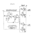
- FIG. 3 is an electrical schematic diagram of a narrow bandpass filter 34 and comparator circuit 36 which form controller 30.
- Filter 34 is tuned to monitor a portion of the wide-band frequency vibrations of skin 22, for example, the mode 2 response of signals detected by accelerometer 28.
- Filter 34 in the described embodiment has a center frequency of 1500 Hz, a gain of 23 dB, a -3 dB bandwidth of 60 Hz and a Q of 25.
- Filter 34 is of conventional construction and includes operational amplifiers 38 and 40 which may be, for example, two parts of a quad operational amplifier LM3900 obtainable from the National Semiconductor Corporation.
- the value of components associated with amplifiers 38 and 40 in filter 34 are selected in accordance with design parameters to obtain the previously described filter characteristics. Such design parameters are well-known and are published, for example, in Application Notes of the LM3900 published by National Semiconductor Corporation.
- Comparator circuit 36 is connected to the output of amplifier 40 and includes an operational amplifier 42 connected as a comparator.
- Amplifier 42 may also be a portion of a quad operational amplifier LM3900.
- An input resistor 44 is connected in series with the output of amplifier 40 and the inverting input of amplifier 42.
- the non inverting input of amplifier 42 is connected to a reference circuit including resistor 46, capacitor 48, resistor 50, and resistor 52.
- Resistor 52 is an adjustable resistor connected in series between resistor 46 and a source of operating voltage, not shown. Values of components 44 through 52 are well-known, and are selected according to design principles such as those published in the aforementioned Application Notes.
- Resistor 52 is adjusted so that the output of amplifier 42, which is normally at a logic HI level, switches to a logic LO level upon detection of 2.54 mm (0.1 inches) of ice upon the surface. That is, the output of amplifier 42 is at a logic HI level whenever the amplitude of mode 2 as shown in Figure 2 is above a predetermined level. When more than 2.54 mm (0.1 inches) of ice accumulate upon surface 22, the amplitude of mode 2 as detected by filter 34 drops off sharply.
- Mode 2 of the acceleration of skin 22 occurs, under normal conditions of no ice, at a frequency of approximately 1500 Hz.
- the presence of ice upon skin 22 will cause the peak of mode 2 response to be either reduced, shifted in frequency, or both.
- the output of filter 34 will sharply decrease upon occurrence of either of these phenomena. Accordingly, the output of amplifier 42 of comparator 36 will reliably change state upon detection of the presence of ice at least 2.54 mm (0.1 inch).
- the output of amplifier 40 is also connected to an amplifier 42A configured as a comparator.
- Components 44A, 46A, 48A, 50A and 52A are identical to corresponding components 44, 46, 48, 50 and 52, respectively.
- variable resistor 52A is adjusted to yield a reference voltage such that the output of amplifier 42A changes state upon detection of 1.27 cm (0.5 inches) of ice.
- controller 30 may include a microcomputer programmed to provide such analysis.
- the invention is not limited to the use of an accelerometer to detect a parameter which is a function of both the input signal and the presence of ice.
- a strain gauge could be used to monitor strain of skin 22 upon generation of deicing pulse of the first level, the strain of skin 22 being a function of both the current pulse supplied to solenoid 20 and of the presence of ice.
- a permanent magnet could be mounted upon the interior surface of skin 22 at a predetermined distance from solenoid 20 in juxtaposition with a Hall effect device. Generation of a current pulse of a first level to solenoid 20 would cause movement of skin 22 and the attached permanent magnet in a manner so as to generate an output from the Hall effect device. Movement of skin 22 is similarly a parameter which is a function of both the level of input signal to solenoid 20 and of the presence of ice.
- Figure 4 shows a further alternative embodiment, in which a current detection device 54 may be connected in series circuit relationship between pulse generator 18 and solenoid 20.
- Device 54 may be, for example, a shunt, a current transformer, or a current detection circuit.
- the presence of ice on skin 22 may cause a loading effect on solenoid 20 which is detectable as a change in the level of current actually being supplied from pulse generator 18 to solenoid 20.
- device 54 may not be as sensitive as a separately mounted sensor such as accelerometer 28 in sensing a parameter which is a function of both the input signal to soleniod 20 and the presence of ice.
- device 54 may be mounted within pulse generator 18 and would not require separate physical mounting upon the measured surface.
- the present invention when used in conjunction with an EIDI system, provides the capability of detecting ice while avoiding unnecessary expenditure of power and unnecessary imposition of fatigue-inducing forces.
- the ice detection capability may be provided with a minimum of increased weight and complexity.
- the invention is not limited to use in conjunction with an electro-impulse deicing system.
- means may be provided for use in conjunction with a pneumatic boot deicing system in which air pressure inputs to the pneumatic boot are provided at first and second levels, with the first level being less than the second level.
- the physical response of the boot to an ice detection input signal of the first level should be function of both the level of the input signal and the presence of ice. Such physical response may then be measured to provide a reliable indication of the presence of the ice without supplying a full deicing input signal to the pneumatic boot, with its concurrent problems of unnecessary fatigue stress to the system.
- a solenoid of a type similarto an EIDI sotenoid, but of greatly reduced current capacity may be mounted in proximity to the inner surface of a thin wall structure to be protected.
- Means such as accelerometer 28 may then be mounted upon the inner surface of the structure to be protected, and a low- level current pulse supplied to the solenoid. The presence of ice is indicated by an output signal from the accelerometer less than the case when no ice is present.
- the present invention provides apparatus for sensing the presence of ice on structural surrfaces while providing minimum increased complexity and weight.
- the invention provides ice detection capability which avoids the unnecessary expenditure of power or imposition of fatigue-inducing forces such that the ice detection system may be reliably incorporated into an automatic ice detection and removal system.
Landscapes
- Engineering & Computer Science (AREA)
- Aviation & Aerospace Engineering (AREA)
- Geophysics And Detection Of Objects (AREA)
- Switches Operated By Changes In Physical Conditions (AREA)
Description
- The invention relates to ice detection systems and, more particularly, to ice detection systems for use in conjunction with ice removal systems.
- The formation of ice on structures is, in certain applications, undesired and indeeed dangerous. For example, the formation of ice upon exterior surfaces of an aircraft in flight is a well-known hazard, causing an increase in weight of the aircraft and a corresponding increase in fuel consumption. More importantly, however, the buildup of ice on wings and control surfaces of aircraft in flight can result in a decrease of lift and a degradation of the control function. Such conditions can result in extreme hazard to the aircraft. Accordingly, various methods have been devised for removal of ice from such aircraft surfaces.
- Known methods of ice removal include the use of flexible pneumatic coverings, or "boots", on the leading edge surfaces of aircraft wings and control surfaces. These boots are periodically provided with pulses of air or other fluid to cause any ice which has accreted on the leading edge surface to be cracked away and removed by action of the airstream over the surface. Another method commonly used is to divert a portion of bleed air from the aircraft engine through passages of airframe structures having surfaces subject to icing, causing such surfaces to heat up and loosen any ice formed on the exterior portion of such surfaces.
- Still another ice removal system is known as electro-impulse deicing (EIDI). In the EIDI system, a solenoid is mounted in proximity to the inner surface of a conductive thin-wall surface of the aircraft. High-current pulses of electrical energy are periodically supplied to the solenoid, causing the formation of eddy currents in portions of the conductive skin juxtaposed with the solenoid. Magnetic fields generated by such eddy currents interact with magnetic fields generated by the solenoid, producing a sudden electrodynamic force upon the portion of the surface containing the eddy currents, which fractures any ice which may have formed on the exterior surface of the skin, permitting its removal by the airstream. Such a system is described in GB-A-1369350.
- All of these deicing systems have proved satisfactory in appropriate applications. However, none of such systems can be operated continuously. Continuous operation of pneumatic boots when icing conditions are not present will result in premature deterioration of the boot, while continuous operation of EIDI systems can produce unnecessary fatigue loading upon the surface of the skin. Bleed air systems require significant amounts of power, causing power to be diverted from the propulsion of the aircraft. This results in increased fuel consumption and in certain power settings of the engines, such as used during landing configuration, can result in such severe loading upon the engine as to result in a hazardous situation. It is therefore desirable to activate deicing systems only upon detection of ice upon critical aircraft surfaces.
- Certain ice detection systems are known in the prior art. Many such systems employ a probe including a vibrating element, the resonant frequency of which is varied by the formation of ice upon the probe permitting such variation in frequency to be sensed and used to generate an ice indication signal. Such a device is shown, for example, in U.S. Patent 3,541,540 to Hughes. Although such probes are useful in many applications it is possible, because of various aerodynamic differences between the structure of the probe and actual aircraft surfaces, that under certain conditions the probe may indicate the presence of ice when ice is not actually forming upon the critical surfaces of the aircraft. Moreover, the comparative rate of icing may be significantly different between the probe and such critical aircraft surfaces. Therefore, currently known ice detection systems are generally employed only in an advisory capacity to provide an indication of the existence of conditions amenable to ice formation upon critical aircraft surfaces and not as an indication of the actual presence of ice on such surfaces.
- It is therefore desirable to provide a system for reliable indication of the actual presence of ice upon critical aircraft surfaces. It is further desirable to provide such a system which is compatible with existing types of deicing systems and which results in a minimum increase in weight and complexity of aircraft systems.
- In accordance with the principles of the present invention, apparatus is provided for sensing and removing ice from a surface. The apparatus includes removal means for exerting an ice removal force upon receipt of an input signal, means for supplying an input signal to the removal means, and means for sensing a parameter which is a function of the input signal and of the presence of ice. The apparatus further includes means for generating an indicating signal when the sensed parameter reaches a predetermined reference level, thereby indicating the presence of ice.
- In a preferred embodiment of the invention, there is provided apparatus for detecting the presence of ice upon the surface of an aircraft equipped with an electro-impulse deicing system, the system including a solenoid mounted in proximity to the surface. The apparatus of the preferred embodiment thus includes means for selectively suppling pulses of first and second levels to the solenoid, the first level being less than the second level. The apparatus of the preferred embodiment further includes means for sensing a parameter which is a function of current pulses of the first level and of the presence of ice, and means for generating an indicating signal when the sensed parameter reaches a predetermined reference level, thereby indicating the presence of ice.
- The accompanying drawings, which are incorporated in and constitute a part of the specification illustrate one embodiment of the invention and, together with the specification, serve to explain the principles of the invention.
-
- Figure 1 is a schematic side view of a portion of an aircraft wing including a preferred embodiment of the invention with an electro-impulse deicing system;
- Figure 2 is a graph of acceleration of a portion of a wing surface versus frequency when subjected to an electro-impulse deicing current pulse;
- Figure 3 is an electrical schematic diagram of a portion of the controller shown in Figure 1; and
- Figure 4 is a view similar to Figure 1 of an alternative embodiment of the present invention.
- Referring now to the drawings, in which like reference characters refer to corresponding elements, Figure 1 shows a side view of a portion of an
aircraft wing 12 incorporating asystem 10 which is a preferred embodiment of the present invention. In accordance with the principles of the present invention, thesystem 10 includes an electro-impulse deicing (EIDI)system 14 which includes apower supply 16, acurrent pulse generator 18, and removal means responsive to an input signal for exerting an ice removal force upon analuminum surface 22 ofwing 12. As embodied herein, the removal means comprises an electro-impulse deicing solenoid 20. - Solenoid 20 is mounted in proximity to the inner surface of a portion of the surface or
skin 22, ofwing 12. When EIDIsystem 14 is used to deiceskin 22, power frompower supply 16 is formed into drive pulses of current to provide a magnetic field strength of 1.0 to 1.5 teslas at a frequency determined by the modal characteristics of the surface being de-iced. Such frequency varies according to the size and geometry of the structure being de-iced. The drive pulses are unipolar pulses with a rise time of approximately 1/4 of the period of the desired modal excitation. For a structure representative of the outboard slot of an aircraft wing, pulses of about 2000 amperes having a rise time of 150 microseconds are generated at a frequency of 1500 Hz. - These drive pulses generate intense magnetic fields in solenoid 20 which induce eddy currents in that portion of
skin 22 juxtaposed with solenoid 20. The eddy currents in turn generate magnetic fields which interact with magnetic fields produced directly by solenoid 20. The interaction between these magnetic fields causes a brief intense electrodynamic force to be exerted upon the portion ofskin 22 juxtaposed with solenoid 20, as indicated by arrows 24. This force causes vibrational movement ofskin 22 as indicated byarrows 26. - In accordance with the principles of the present invention, means are provided for sensing a parameter which is a function of the input signal to solenoid 20 and of the presence of ice. As embodied herein, the sensing means includes an
accelerometer 28 fixedly attached to the inner surface ofskin 22 which detects the vibrational movement thereof.Accelerometer 28 is positioned at a predetermined distance from soleniod 20, the distance being dependent upon the actual configuration of the specific surface upon which the system is mounted. For example,accelerometer 28 may be positioned at a distance from solenoid 20 of multiples of one half wavelength of the skin modal frequency; that is, the frequency at which theskin 22 vibrates when stressed by electrodynamic forces produced by drive pulses to solenoid 20. The drive pulse frequency should be as close as possible to the skin modal frequency but need not be the same. In the described embodiment, for example, 1500 Hz drive pulse produce a skin modal frequency of 1566 Hz. For a particular application involving a specific structural configuration, some experimentation may be necessary to determine an acceptable position foraccelerometer 28 so that proper output thereof is obtained. - The degree of vibration of
skin 22 caused by solenoid 20 is dependent upon the intensity of current pulses applied to solenoid 20. Moreover, the presence of ice will change the manner in whichskin 22 responds to electrodynamic forces imposed thereon by solenoid 20. Such changes in response are detected byaccelerometer 28. Thus,accelerometer 28 senses a parameter which is a function of the input signal to solenoid 20 and of the presence of ice. The output ofaccelerometer 28 is supplied to acontroller 30 to be more completely described. - The elements just described may thus be used to detect the presence of ice on
skin 22. Since application of a full 1.0 to 1.5 tesla EIDI pulse toskin 22 for ice detection purposes would result in unnecessary stress toskin 22, different energy levels from those used in conventional EIDI systems may be employed for ice sensing. Accordingly,controller 30 provides a control signal topulse generator 18 to causepulse generator 18 to selectively apply pulses of first and second levels to solenoid 20. The first level, which is used for ice detection, is less than the second level. In the preferred embodiment, fields of the second level are generated at 1 to 1.5 teslas to cause sufficient force uponskin 22 to remove ice accreted thereon. Pulses of the first level are generated at a level sufficient to produce a signal distinguishable over ambient noise from airflow, precipitation, etc., yet not so great as to cause unnecessary fatigue stress, noise, and power consumption. Generally, pulses of the first level should be approximately an order of magnitude less than pulses of the second level. In the preferred embodiment, fields of the first level are approximately .1 to .15 teslas. This causes electrodynamic forces to be generated uponskin 22 much less than the ice removal pulses of the second level. However, forces generated uponskin 22 by pulses of the first level are sufficient to generate mechanical waves inskin 22 causing vibrational movement which can be detected byaccelerometer 38. In the deserved embedirHt, first and second level pulses of 1.0-1.5 teslas and 0.1-0.15 teslas may be generated by current pulses of 1500-2000 amperes and 150-200 amperes, respectively. - The presence of ice upon
skin 22 affects such waves generated by pulses of the first level. Accordingly, movement ofskin 22 caused by current pulses of the first level is a parameter which is a function of the pulse current level and of the presence of ice uponskin 22. - The invention provides means for generating an ice-presence indicating signal when the sensed parameter reaches a predetermined reference level. As embodied herein, such generating means comprises
controller 30. Signals fromaccelerometer 28 which are detected following generation of first level pulses are supplied tocontroller 30. These signals are compared incontroller 30 to a predetermined reference level. If the signals fromacceleratometer 28 are below the reference level,controller 30 indicates the presence of ice uponskin 22 and generates an ice-presence indicating signal over anoutput terminal 32 which energizes a warning indicator (not shown) in the cockpit announcing the presence of ice uponskin 22. The predetermined reference level is a level determined either experimentally or by mathematical calculation. In addition, the invention can be configured such that the presence of ice is indicated by either a value that exceeds the reference level or is lower than the reference level. - At certain applications, it may be determined that best performance may be obtained by the use of ice detection pulses (i.e. pulses of the first level) at a different frequency than ice removal pulses (i.e. pulses of the second level). In such cases,
controller 30 is constructed to operatepulse generator 18 so as to generate pulses of the appropriate frequency. -
Controller 30 may be constructed so as to causegenerator 18 to continuously and automatically generate pulses of the first level. If ice is detected,controller 30 supplies a signal topulse generator 18, causingpulse generator 18 to automatically begin generating second level current pulses and remove ice from the surface. - When
skin 22 is subjected to an electrodynamic force generated by solenoid 20, it vibrates over a wide frequency band. That is, it vibrates in a plurality of modes, which modes are sensed byaccelerometer 28. - Figure 2 shows a graph of the output of
accelerometer 28 as a function of frequency, whenaccelerometer 28 is attached to the inner surface of a test structure representative of an outboard slat of an aircraft wing and subjected to an an electro-impulse deicing current pulse at a frequency of 1500 Hz. As can be seen, the acceleration of the surface occurs in a plurality of vibrational modes, indicated by peaks in Figure 2. The first peak at the left-hand side of Figure 2 indicates acceleration at the fundamental skin modal frequency of 1170 Hz, ormode 1. The sneond peak indicates acceleration in a second mode at a higher frequency than the fundamental frequency. Similarly, other modes of acceleration are shown in Figure 2. - Figure 3 is an electrical schematic diagram of a
narrow bandpass filter 34 andcomparator circuit 36 which formcontroller 30.Filter 34 is tuned to monitor a portion of the wide-band frequency vibrations ofskin 22, for example, themode 2 response of signals detected byaccelerometer 28.Filter 34 in the described embodiment has a center frequency of 1500 Hz, a gain of 23 dB, a -3 dB bandwidth of 60 Hz and a Q of 25.Filter 34 is of conventional construction and includesoperational amplifiers amplifiers filter 34 are selected in accordance with design parameters to obtain the previously described filter characteristics. Such design parameters are well-known and are published, for example, in Application Notes of the LM3900 published by National Semiconductor Corporation. -
Comparator circuit 36 is connected to the output ofamplifier 40 and includes anoperational amplifier 42 connected as a comparator.Amplifier 42 may also be a portion of a quad operational amplifier LM3900. Aninput resistor 44 is connected in series with the output ofamplifier 40 and the inverting input ofamplifier 42. The non inverting input ofamplifier 42 is connected to a referencecircuit including resistor 46, capacitor 48, resistor 50, and resistor 52. Resistor 52 is an adjustable resistor connected in series betweenresistor 46 and a source of operating voltage, not shown. Values ofcomponents 44 through 52 are well-known, and are selected according to design principles such as those published in the aforementioned Application Notes. Resistor 52 is adjusted so that the output ofamplifier 42, which is normally at a logic HI level, switches to a logic LO level upon detection of 2.54 mm (0.1 inches) of ice upon the surface. That is, the output ofamplifier 42 is at a logic HI level whenever the amplitude ofmode 2 as shown in Figure 2 is above a predetermined level. When more than 2.54 mm (0.1 inches) of ice accumulate uponsurface 22, the amplitude ofmode 2 as detected byfilter 34 drops off sharply. -
Mode 2 of the acceleration ofskin 22 occurs, under normal conditions of no ice, at a frequency of approximately 1500 Hz. The presence of ice uponskin 22 will cause the peak ofmode 2 response to be either reduced, shifted in frequency, or both. The output offilter 34 will sharply decrease upon occurrence of either of these phenomena. Accordingly, the output ofamplifier 42 ofcomparator 36 will reliably change state upon detection of the presence of ice at least 2.54 mm (0.1 inch). - The output of
amplifier 40 is also connected to an amplifier 42A configured as a comparator.Components 44A, 46A, 48A, 50A and 52A are identical tocorresponding components - The design of the response of
filter 34 is not limited to detection of themode 2 response peak of acceleration ofskin 22 but may be modified to detect any modal response peak desired, as dictated by the specific application. Moreover, in certain applications more sophisticated analysis of the output of accelerometer may be desirable. In such applications,controller 30 may include a microcomputer programmed to provide such analysis. - The invention is not limited to the use of an accelerometer to detect a parameter which is a function of both the input signal and the presence of ice. For example, a strain gauge could be used to monitor strain of
skin 22 upon generation of deicing pulse of the first level, the strain ofskin 22 being a function of both the current pulse supplied to solenoid 20 and of the presence of ice. Similarly, a permanent magnet could be mounted upon the interior surface ofskin 22 at a predetermined distance from solenoid 20 in juxtaposition with a Hall effect device. Generation of a current pulse of a first level to solenoid 20 would cause movement ofskin 22 and the attached permanent magnet in a manner so as to generate an output from the Hall effect device. Movement ofskin 22 is similarly a parameter which is a function of both the level of input signal to solenoid 20 and of the presence of ice. - Figure 4 shows a further alternative embodiment, in which a
current detection device 54 may be connected in series circuit relationship betweenpulse generator 18 and solenoid 20.Device 54 may be, for example, a shunt, a current transformer, or a current detection circuit. The presence of ice onskin 22 may cause a loading effect on solenoid 20 which is detectable as a change in the level of current actually being supplied frompulse generator 18 to solenoid 20. - Under certain conditions, the use of
device 54 may not be as sensitive as a separately mounted sensor such asaccelerometer 28 in sensing a parameter which is a function of both the input signal to soleniod 20 and the presence of ice. However,device 54 may be mounted withinpulse generator 18 and would not require separate physical mounting upon the measured surface. - The present invention, when used in conjunction with an EIDI system, provides the capability of detecting ice while avoiding unnecessary expenditure of power and unnecessary imposition of fatigue-inducing forces. By utilizing components of the EIDI system, the ice detection capability may be provided with a minimum of increased weight and complexity.
- The invention is not limited to use in conjunction with an electro-impulse deicing system. For example, means may be provided for use in conjunction with a pneumatic boot deicing system in which air pressure inputs to the pneumatic boot are provided at first and second levels, with the first level being less than the second level. The physical response of the boot to an ice detection input signal of the first level should be function of both the level of the input signal and the presence of ice. Such physical response may then be measured to provide a reliable indication of the presence of the ice without supplying a full deicing input signal to the pneumatic boot, with its concurrent problems of unnecessary fatigue stress to the system.
- The principles of the invention may also be applied in applications not including any type of deicing system. For example, where it is desired to provide an ice detection capability without any components external to the protected structure, a solenoid of a type similarto an EIDI sotenoid, but of greatly reduced current capacity may be mounted in proximity to the inner surface of a thin wall structure to be protected. Means such as
accelerometer 28 may then be mounted upon the inner surface of the structure to be protected, and a low- level current pulse supplied to the solenoid. The presence of ice is indicated by an output signal from the accelerometer less than the case when no ice is present. - It can be seen, therefore, that the present invention provides apparatus for sensing the presence of ice on structural surrfaces while providing minimum increased complexity and weight. Similarly, the invention provides ice detection capability which avoids the unnecessary expenditure of power or imposition of fatigue-inducing forces such that the ice detection system may be reliably incorporated into an automatic ice detection and removal system.
- It will be apparent to those skilled in the art that various modifications and variations can be made in the system of the present invention without departing from the scope of the invention. Thus, it is intended that the present invention cover the modifications and variations of this invention provided they come within the scope of the appended claims and their equivalents.
Claims (19)
Applications Claiming Priority (2)
| Application Number | Priority Date | Filing Date | Title |
|---|---|---|---|
| US06/801,848 US4775118A (en) | 1985-11-26 | 1985-11-26 | Ice detecting system |
| US801848 | 1985-11-26 |
Publications (3)
| Publication Number | Publication Date |
|---|---|
| EP0224941A2 EP0224941A2 (en) | 1987-06-10 |
| EP0224941A3 EP0224941A3 (en) | 1988-11-02 |
| EP0224941B1 true EP0224941B1 (en) | 1990-12-05 |
Family
ID=25182178
Family Applications (1)
| Application Number | Title | Priority Date | Filing Date |
|---|---|---|---|
| EP86201385A Expired EP0224941B1 (en) | 1985-11-26 | 1986-08-06 | Ice detecting system |
Country Status (3)
| Country | Link |
|---|---|
| US (1) | US4775118A (en) |
| EP (1) | EP0224941B1 (en) |
| DE (2) | DE3676056D1 (en) |
Families Citing this family (28)
| Publication number | Priority date | Publication date | Assignee | Title |
|---|---|---|---|---|
| US4875644A (en) * | 1988-10-14 | 1989-10-24 | The B. F. Goodrich Company | Electro-repulsive separation system for deicing |
| US5035140A (en) * | 1988-11-03 | 1991-07-30 | The Boeing Company | Self cleaning liquid level detector |
| US5398547A (en) * | 1989-01-10 | 1995-03-21 | Innovative Dynamics, Inc. | Apparatus for measuring ice distribution profiles |
| US5206806A (en) * | 1989-01-10 | 1993-04-27 | Gerardi Joseph J | Smart skin ice detection and de-icing system |
| US5195046A (en) * | 1989-01-10 | 1993-03-16 | Gerardi Joseph J | Method and apparatus for structural integrity monitoring |
| SE8901842L (en) * | 1989-05-24 | 1990-11-25 | Frigoscandia Contracting Ab | SETTING AND DEVICE FOR DEFINING A FAN |
| US5117687A (en) * | 1990-01-11 | 1992-06-02 | Gerardi Joseph J | Omnidirectional aerodynamic sensor |
| US5457630A (en) * | 1992-11-18 | 1995-10-10 | Aers/Midwest, Inc. | System for onboard lift analysis and apparatus therefor |
| US5796612A (en) | 1992-11-18 | 1998-08-18 | Aers/Midwest, Inc. | Method for flight parameter monitoring and control |
| US6002972A (en) * | 1992-11-18 | 1999-12-14 | Aers/Midwest, Inc. | Method and apparatus for measuring forces based upon differential pressure between surfaces of an aircraft |
| US5523959A (en) * | 1994-04-25 | 1996-06-04 | The United States Of America As Represented By The Administrator Of The National Aeronautics And Space Administration | Ice detector and deicing fluid effectiveness monitoring system |
| US5557261A (en) * | 1994-05-06 | 1996-09-17 | Nichols Research Corporation | Ice monitoring and detection system |
| US5497100A (en) * | 1994-10-17 | 1996-03-05 | Hughes Aircraft Company | Surface condition sensing system |
| US6052056A (en) * | 1996-04-26 | 2000-04-18 | Icg Technologies, Llc | Substance detection system and method |
| NO313219B1 (en) * | 2000-12-07 | 2002-08-26 | Protura As | Apparatus and method for removing foreign matter such as ice / snow from an overhead line |
| US20090230239A1 (en) * | 2006-03-17 | 2009-09-17 | Stothers Ian Mcgregor | Ice protection power supply |
| WO2008085550A2 (en) * | 2006-08-02 | 2008-07-17 | Battelle Memorial Institute | Electrically conductive coating composition |
| IL185134A (en) * | 2007-08-08 | 2013-10-31 | Amihay Gornik | Mechanical vibration deicing system |
| FR2922522B1 (en) * | 2007-10-22 | 2010-04-16 | Aircelle Sa | PIEZOELECTRIC DEFROSTING OF AN AIR INPUT |
| DE102008005700B4 (en) * | 2007-12-28 | 2014-05-22 | Airbus Operations Gmbh | System and method for measuring and preventing icing in a pipeline |
| US8779945B2 (en) | 2010-03-17 | 2014-07-15 | Sikorsky Aircraft Corporation | Virtual ice accretion meter display |
| US9737916B2 (en) | 2015-08-24 | 2017-08-22 | Lockheed Martin Corporation | Dynamic resonance system and method for the anti-icing and de-icing of inlet grids |
| RU2648656C2 (en) * | 2016-01-29 | 2018-03-27 | Общество с ограниченной ответственностью "Научно-производственный центр "Судовые электротехнические системы" (ООО "НПЦ "СЭС") | Automated electropulse de-icing device |
| JP6743458B2 (en) * | 2016-04-01 | 2020-08-19 | セイコーエプソン株式会社 | Observation system and control method of observation system |
| FR3078948A1 (en) * | 2018-03-19 | 2019-09-20 | Safran Nacelles | METHOD FOR ELECTRICALLY SUPPLYING AN ULTRASONIC DEFICIENT DEFROSTING AND ANTI-GLAZING |
| US11802756B2 (en) | 2020-08-18 | 2023-10-31 | Steven R. Weeres | Ice thickness transducer |
| JP7644628B2 (en) * | 2021-03-19 | 2025-03-12 | 株式会社Subaru | Ice detection device |
| FR3124490A1 (en) * | 2021-06-29 | 2022-12-30 | Airbus Operations | IMPROVED AIR SUPPLY SYSTEM FOR AN AIRCRAFT PNEUMATIC DE-ICING ASSEMBLY, AND AIRCRAFT INCLUDING SUCH AIR SUPPLY SYSTEM. |
Family Cites Families (10)
| Publication number | Priority date | Publication date | Assignee | Title |
|---|---|---|---|---|
| US3240054A (en) * | 1962-12-24 | 1966-03-15 | Gabb Special Products Inc | Ice detector |
| US3341835A (en) * | 1964-11-05 | 1967-09-12 | Rosemount Eng Co Ltd | Ice detector |
| US3541540A (en) * | 1968-07-26 | 1970-11-17 | Rosemount Eng Co Ltd | Ice detectors |
| GB1369350A (en) * | 1972-11-14 | 1974-10-02 | Levin I A | Device for de-icing thin-walled structures |
| US4176524A (en) * | 1976-11-10 | 1979-12-04 | Matsushita Electric Industrial Co., Ltd. | Frost detector |
| US4365131A (en) * | 1980-06-27 | 1982-12-21 | Hansman Jr Robert J | Microwave ice prevention system |
| US4470123A (en) * | 1982-01-05 | 1984-09-04 | Miami R & D Limited Partnership | Microwave ice accretion meter |
| US4461178A (en) * | 1982-04-02 | 1984-07-24 | The Charles Stark Draper Laboratory, Inc. | Ultrasonic aircraft ice detector using flexural waves |
| US4514619A (en) * | 1982-09-30 | 1985-04-30 | The B. F. Goodrich Company | Indirect current monitoring via voltage and impedance monitoring |
| US4553137A (en) * | 1983-06-01 | 1985-11-12 | Rosemount Inc. | Non-intrusive ice detector |
-
1985
- 1985-11-26 US US06/801,848 patent/US4775118A/en not_active Expired - Fee Related
-
1986
- 1986-08-06 EP EP86201385A patent/EP0224941B1/en not_active Expired
- 1986-08-06 DE DE8686201385T patent/DE3676056D1/en not_active Expired - Lifetime
- 1986-12-22 DE DE19863643995 patent/DE3643995A1/en not_active Withdrawn
Also Published As
| Publication number | Publication date |
|---|---|
| DE3643995A1 (en) | 1988-06-30 |
| US4775118A (en) | 1988-10-04 |
| EP0224941A3 (en) | 1988-11-02 |
| EP0224941A2 (en) | 1987-06-10 |
| DE3676056D1 (en) | 1991-01-17 |
Similar Documents
| Publication | Publication Date | Title |
|---|---|---|
| US4775118A (en) | Ice detecting system | |
| US5191791A (en) | Piezoelectric sensor | |
| US5551288A (en) | Measuring ice distribution profiles on a surface with attached capacitance electrodes | |
| US4524620A (en) | In-flight monitoring of composite structural components such as helicopter rotor blades | |
| US5467944A (en) | Detector for indicating ice formation on the wing of an aircraft | |
| US20180037329A1 (en) | Method and apparatus for inhibiting formation of and/or removing ice from aircraft components | |
| CA1214255A (en) | Ice detector | |
| US3712122A (en) | Aircraft hard landing indicator | |
| US4300119A (en) | Power generator for telemetry transmitter | |
| WO2008131098A1 (en) | Ice detection | |
| US7856884B2 (en) | Method for performing a ground vibration test in airplanes | |
| US5341677A (en) | Method of aerodynamic stall-turbulence indication | |
| EP3058429B1 (en) | Global airframe health characterization | |
| EP0643647A1 (en) | Sensor for measuring force and extension in tyres | |
| US7461819B2 (en) | Method for using a steerable tall fin to reduce the vibration generated on the fuselage of a helicopter | |
| US20060027701A1 (en) | Method and a device for using a tiltable stabilizer to reduce vibration generated on the fuselage of a helicopter | |
| US5390543A (en) | Method and apparatus for in-flight shake testing of an aircraft fuselage | |
| EP4101767A1 (en) | Mechanical ice protection system for aerodynamic surfaces | |
| US20030188579A1 (en) | System and method for determining status of an object by insonification | |
| US20080128556A1 (en) | System and method for detecting ice formation on an aircraft | |
| US5986582A (en) | Helicopter rotor/engine warning system | |
| EP1312815B1 (en) | Collective head bearing monitor | |
| CN113148122A (en) | Brake control method and system | |
| US5272400A (en) | Expulsive ice detector | |
| Hinchliffe et al. | Tonal active control in production on a large turbo-prop aircraft |
Legal Events
| Date | Code | Title | Description |
|---|---|---|---|
| PUAI | Public reference made under article 153(3) epc to a published international application that has entered the european phase |
Free format text: ORIGINAL CODE: 0009012 |
|
| AK | Designated contracting states |
Kind code of ref document: A2 Designated state(s): DE FR GB IT NL |
|
| PUAL | Search report despatched |
Free format text: ORIGINAL CODE: 0009013 |
|
| AK | Designated contracting states |
Kind code of ref document: A3 Designated state(s): DE FR GB IT NL |
|
| 17P | Request for examination filed |
Effective date: 19881202 |
|
| 17Q | First examination report despatched |
Effective date: 19900118 |
|
| ITF | It: translation for a ep patent filed | ||
| GRAA | (expected) grant |
Free format text: ORIGINAL CODE: 0009210 |
|
| AK | Designated contracting states |
Kind code of ref document: B1 Designated state(s): DE FR GB IT NL |
|
| ET | Fr: translation filed | ||
| REF | Corresponds to: |
Ref document number: 3676056 Country of ref document: DE Date of ref document: 19910117 |
|
| ITTA | It: last paid annual fee | ||
| PLBE | No opposition filed within time limit |
Free format text: ORIGINAL CODE: 0009261 |
|
| STAA | Information on the status of an ep patent application or granted ep patent |
Free format text: STATUS: NO OPPOSITION FILED WITHIN TIME LIMIT |
|
| 26N | No opposition filed | ||
| PGFP | Annual fee paid to national office [announced via postgrant information from national office to epo] |
Ref country code: GB Payment date: 19920730 Year of fee payment: 7 |
|
| PGFP | Annual fee paid to national office [announced via postgrant information from national office to epo] |
Ref country code: FR Payment date: 19920828 Year of fee payment: 7 |
|
| PGFP | Annual fee paid to national office [announced via postgrant information from national office to epo] |
Ref country code: NL Payment date: 19920831 Year of fee payment: 7 Ref country code: DE Payment date: 19920831 Year of fee payment: 7 |
|
| PG25 | Lapsed in a contracting state [announced via postgrant information from national office to epo] |
Ref country code: GB Effective date: 19930806 |
|
| PG25 | Lapsed in a contracting state [announced via postgrant information from national office to epo] |
Ref country code: NL Effective date: 19940301 |
|
| GBPC | Gb: european patent ceased through non-payment of renewal fee |
Effective date: 19930806 |
|
| NLV4 | Nl: lapsed or anulled due to non-payment of the annual fee | ||
| PG25 | Lapsed in a contracting state [announced via postgrant information from national office to epo] |
Ref country code: FR Effective date: 19940429 |
|
| PG25 | Lapsed in a contracting state [announced via postgrant information from national office to epo] |
Ref country code: DE Effective date: 19940503 |
|
| REG | Reference to a national code |
Ref country code: FR Ref legal event code: ST |
|
| PG25 | Lapsed in a contracting state [announced via postgrant information from national office to epo] |
Ref country code: IT Free format text: LAPSE BECAUSE OF NON-PAYMENT OF DUE FEES;WARNING: LAPSES OF ITALIAN PATENTS WITH EFFECTIVE DATE BEFORE 2007 MAY HAVE OCCURRED AT ANY TIME BEFORE 2007. THE CORRECT EFFECTIVE DATE MAY BE DIFFERENT FROM THE ONE RECORDED. Effective date: 20050806 |