EP0224650A2 - Flow inducing means for small volume containers - Google Patents
Flow inducing means for small volume containers Download PDFInfo
- Publication number
- EP0224650A2 EP0224650A2 EP86111138A EP86111138A EP0224650A2 EP 0224650 A2 EP0224650 A2 EP 0224650A2 EP 86111138 A EP86111138 A EP 86111138A EP 86111138 A EP86111138 A EP 86111138A EP 0224650 A2 EP0224650 A2 EP 0224650A2
- Authority
- EP
- European Patent Office
- Prior art keywords
- blood
- container
- collector
- further characterized
- cross
- Prior art date
- Legal status (The legal status is an assumption and is not a legal conclusion. Google has not performed a legal analysis and makes no representation as to the accuracy of the status listed.)
- Granted
Links
Images


Classifications
-
- A—HUMAN NECESSITIES
- A61—MEDICAL OR VETERINARY SCIENCE; HYGIENE
- A61B—DIAGNOSIS; SURGERY; IDENTIFICATION
- A61B5/00—Measuring for diagnostic purposes; Identification of persons
- A61B5/15—Devices for taking samples of blood
- A61B5/150007—Details
- A61B5/150343—Collection vessels for collecting blood samples from the skin surface, e.g. test tubes, cuvettes
-
- A—HUMAN NECESSITIES
- A61—MEDICAL OR VETERINARY SCIENCE; HYGIENE
- A61B—DIAGNOSIS; SURGERY; IDENTIFICATION
- A61B5/00—Measuring for diagnostic purposes; Identification of persons
- A61B5/15—Devices for taking samples of blood
- A61B5/150007—Details
- A61B5/150015—Source of blood
- A61B5/150022—Source of blood for capillary blood or interstitial fluid
-
- A—HUMAN NECESSITIES
- A61—MEDICAL OR VETERINARY SCIENCE; HYGIENE
- A61B—DIAGNOSIS; SURGERY; IDENTIFICATION
- A61B5/00—Measuring for diagnostic purposes; Identification of persons
- A61B5/15—Devices for taking samples of blood
- A61B5/150007—Details
- A61B5/150206—Construction or design features not otherwise provided for; manufacturing or production; packages; sterilisation of piercing element, piercing device or sampling device
- A61B5/150213—Venting means
-
- B—PERFORMING OPERATIONS; TRANSPORTING
- B01—PHYSICAL OR CHEMICAL PROCESSES OR APPARATUS IN GENERAL
- B01L—CHEMICAL OR PHYSICAL LABORATORY APPARATUS FOR GENERAL USE
- B01L3/00—Containers or dishes for laboratory use, e.g. laboratory glassware; Droppers
- B01L3/50—Containers for the purpose of retaining a material to be analysed, e.g. test tubes
- B01L3/508—Rigid containers without fluid transport within
- B01L3/5082—Test tubes per se
-
- B—PERFORMING OPERATIONS; TRANSPORTING
- B01—PHYSICAL OR CHEMICAL PROCESSES OR APPARATUS IN GENERAL
- B01L—CHEMICAL OR PHYSICAL LABORATORY APPARATUS FOR GENERAL USE
- B01L2300/00—Additional constructional details
- B01L2300/08—Geometry, shape and general structure
- B01L2300/0848—Specific forms of parts of containers
- B01L2300/0858—Side walls
Definitions
- This invention relates to a blood collection assembly incorporating a microcollection container.
- the invention is an improvement over the collection assembly described and claimed in U.S. Patent 4,397,318, issued August 9, 1983, which is hereby incorporated by reference in its entirety.
- This invention is related, also, to the inventions described and claimed in co-pending U.S. Patent Applications Serial No. 743,250 and 743,534, both filed June 11, 1985.
- the earlier patent involved the use of a scoop collector for connection to a blood microcollection container for engaging a puncture wound to obtain a blood sample from an individual for subsequent examination of that sample for the determination of the presence or absence of some disease or other problem in a patient.
- the scoop-type blood collection device provides a substantially larger engaging surface for engaging the puncture for collecting the blood, and a substantially larger transfer surface for rapidly transferring the blood from the collector into the microcollection container. Because of the relatively large engaging surface for engaging the puncture wound, the arrangement does not require a precise positioning of the scoop engaging surface in order to initiate and rapidly transfer a quantity of blood to the microcollection container.
- a separate or integral elongated blood flow inducing member which serves as a guide for inducing blood flow passage along a surface, and as a bridge, inducing blood flow across a transition point between two parts in a blood collection assembly.
- Representative blood flow inducing members include, for example, an elongated rod or strip arrangement incorporated into a blood microcollection assembly in such a way that the collected blood is guided from the collector continuously into the associated collection container. For this reason, capillary action causing blood "hang-up" does not take place and blood flows rapidly through the collector into the collection tube or reservoir passage. This in turn reduces blood sample waste in the very small total quantities involved, resulting in a larger specimen yield.
- the invention in the blood collection tube, once a sample is collected there and the tube closed, the invention induces flow of the sample back and forth to enhance mixing of the collected sample with other components in the tube. Moreover, such an arrangement reduces the need for incorporating expensive wetting agents in the collector devices of the invention, either as a component of the material forming the devices or as a separately applied surfactant. Also, there is an avoidance of any reaction between the wetting agents and the sample being collected.
- this invention includes separate members such as rods or strips.
- elongated flow inducing members may be formed during the molding of the blood collection assembly parts. They are positioned in the collector and along the walls of the tube in which the specimen is taken.
- the invention induces sequentially, rapid flow in the collector, provides rapid bridging or transition of that flow from the collector to the tube wall, and finally, rapid flow along the tube wall to the bottom thereof.
- a single film strip of flexible material comprised of polyethylene film may be 0.05 millimeters (mm) thick and 1.52 mm wide.
- a rigid polypropylene strip may be 0.25 mm thick and 0.91 mm wide.
- a solid rod may be comprised of polytetrafluoroethylene and have a diameter of 0.76 mm.
- a tube-shaped strip may be comprised of glass with an O.D. of 0.91 mm. The length will vary depending upon the different applications to be described below.
- the elongated flow inducing members of the invention in the form of integral or separate rods, strips or indentations provide a continuous flow inducing or guiding surface for the sample being collected from the initial puncture wound to the final reservoir and they may be separately formed, and either merely positioned or adhered to the walls of the objects involved, or they may be incorporated into the molds forming the objects themselves.
- the invention may be in the form of flat strips, or they may be square, round, or semi-round objects in cross-section.
- they may take the form of indentations in the walls, for example, of a collection tube, or the collector.
- FIG. 1 illustrates the invention as employed in a blood collection assembly utilizing a scoop collector as taught and claimed in the above noted United States Patent No. 4,397,318 which scoop collector is attached to the open end 11 of a blood collection reservoir or tube 14, with the collector 12 and the reservoir 14 combining to form a blood collection assembly 10. It should be understood that this is in the form of a microcollection assembly as practitioners-in-the-art will understand.
- the assembly incorporates the invention in the form of a film strip 18 one end of which is partially adhered to surface 26 of collector 12 and extends along the surface 24 of reservoir 14. While strip 18 is adhered to surface 26, it is to be understood that it is within the purview of this invention that the elongated flow inducing member may be merely positioned without adherence in desired locations in a collection assembly.
- the strip 18 serves to provide a transition or bridge across the inner end of the inner surface 26 of collector 12 onto the surface 24 of reservoir 14 at the transition point 20 thereof.
- collector 40 is shown similar to the collector 12 described in Fig. 1, However, collector 40 has incorporated therein one form of the elongated blood flow inducing member of the invention as a molded in place rod 44. That is, when the mold is prepared for formulating a plurality of collectors 40 for mass production, the mold includes provision for the molded rod 44.
- Collector 40 includes the vent area 46 in the same manner as the vent in collector 12 noted above with the annular skirt 48 which serves to provide a space 49 for the friction fit of the open end of a collector reservoir 14.
- the molded-in rod in the embodiment shown in the Figs.
- 2(a), 2(b) and 2(c) serves to provide the transitional guiding surface for inducing flow of a blood sample passing along the surface 42 of collector 40 with the end 50 being positioned adjacent the internal surface of the associated reservoir when the collector is fitted in place on the open end of the reservoir in the same manner as described in Fig. 1 above.
- a longitudinal sectional view of a blood collection reservoir 52 is shown. It will be understood by practitioners-in-the-art that the reservoir 52 is a microcollection container for receiving minute quantities of blood drawn from a puncture wound in the finger, ear or in the case of infants, perhaps, in the heel. It is important that the blood be collected rapidly from this wound and introduced into the tube or reservoir 52 toward the bottom 51 thereof for subsequent testing of the blood sample. It is important that the blood be drawn and introduced into these very small tubes as rapidly as possible prior to the coagulation thereof. Thus, as shown in Fig. 3, a flexible film-strip 54 is shown positioned along the internal surface of tube 52.
- a collector as described above, would be fitted on the rim 56 of the open end of the tube 52 so as to introduce into reservoir 52 a blood sample.
- the strip is posi tioned along the tube's internal surface in order to induce and guide the flow of the blood sample to the closed end thereof as rapidly as possible.
- the blood sample does not "hang-up" along the internal surface of tube 52 and slow up the collection of the blood sample.
- strip 54 induces flow of the sample back and forth to enhance a desired mixing action.
- Fig. 3(a) shows the end view of the reservoir or tube 52 shown in Fig. 3. This view shows the configuration and lateral extent of flexible film strip 54 as positioned in tube 52.
- FIG. 4(a) shows a rigid film strip 58, as opposed to the flexible film strip described in Figs. 3 and 3(a) above.
- Film strip 58 as is shown in Fig. 4(a), retains original shape across lateral cross-section, as opposed to the conforming configuration shown of film strip 54 in Figs. 3 and 3(a).
- Fig. 4(b) shows the embodiment of the invention in the form of a round rod 59 while Fig. 4(c) shows a round rod in the form of a hollow tubular rod 60, as opposed to a solid rod 59.
- Fig. 4(d) shows a rectangular solid rod 62.
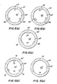
- Figs. 5(a), 5(b), 5(c), 5(d) and 5(e) various forms of the elongated blood flow inducing members of the invention are shown in a blood collection reservoir 65 with an end rim 62, with the collector having incorporated therein during the formation thereof, an elongated molded in arrangement for inducing and directing the flow of blood along the internal surface 63 thereof.
- Fig. 5(a) three rectangular protrusions 64 are shown spaced equally around the circumference of a surface 63. These protrusions extend along the longitudinal extent of the reservoir 65 in the same manner as shown in Fig. 3.
- Fig. 5(b) shows protrusions 66 spaced in the same manner around the circumference of surface 63. In this case, the protrusions 66 are oriented at an angle, as shown for guiding a blood sample along the surface 63.
- Fig. 5(c) is representative of multiple protrusions 68 which may serve to form a guiding passage 69 therebetween.
- the embodiments shown in Fig. 5(d) provides protrusions 70 which cooperate as shown to provide a semi-capillary passage 72 therebetween for a more positive direction of the flow of a blood sample along the surface 63.
- Fig. 5(e) shows an embodiment wherein indentations or depressions 74 are incorporated into the surface 63 for enhancing the passage or flow of blood along the surface 63.
- the average blood microcollection container utilized with the invention herein is 43.18 mm. long. Its internal diameter is 6.17 mm. plus or minus 0.05 mm. Its outer diameter averages 9.71 mm. plus or minus 0.05 mm.
- the unplugged capacity of the container prior to having a cap placed on the open end thereof is 1.05 ml. plus or minus 0.05 ml.
- the plugged capacity of the collectors is 0.925 ml. plus or minus 0.025 ml. Since these collection containers are made of a thermoplastic material in order to provide a material which is moldable, the internal surfaces of blood collection containers have a tendency to be hydrophobic.
- the various forms and/or embodiments of the invention here serve to enhance the flow of blood along these surfaces. It is conventional, in the past, in order to provide wettability to such surfaces, to include or incorporate additives into the thermoplastic material when it is formed or coat the surface after molding, in order to provide wettability. Of course, these additives contribute to the added cost of such containers, limit their shelf-life, and adversely impact the function of the device by in some cases interacting with the specimen being collected. All of these disadvan tages are removed with the use of the device herein, thus making the arrangements herein very attractive from a commercial mass production standpoint. It will be understood, further, that the device of the invention is much more attractive for those who must purchase and use such devices on a continuous basis. Such devices are used throughout the United States, literally in the millions in the course of a year.
- the various embodiments of the invention will be comprised of a clear molded thermoplastic such as a polypropylene, for example.
- a clear molded thermoplastic such as a polypropylene
- microcollection containers and associated tops or caps have been shown, it should be understood that it is within the purview of this invention to provide other forms of microcollection containers with differently configured cooperating caps or tops, as long as they can be configured to receive the appropriate embodiments of the various elongated flow inducing members of the invention, whether such members are incorporated during the formation in the mold of such microcollection containers with associated tops or whether they are separately formed and placed in or adhered to the microcollection assemblies which are to be used with the inventions herein.
- a plurality of longitudinal protrusions or indentations may be spaced equally around the entire collector circumference of a blood collector to give a sectional view of the collector a fluted appearance. Moreover, one or more half length elongated protrusions or indentations may be positioned to extend from the open mouth of the collector to a point half way along the length. Then, one or more half-length elongated protrusions or indentations may extend from the halfway point along the collector to the closed end.
- this second set is off-set from the first set so that liquid following the guiding surface of such protrusions or indentations is forced to "break-up" its pattern half-way along the length of the collector.
- mixing of a blood sample with additives in the collector for example, is enhanced.
- Other variations for mixing include placing such protrusions or indentations at angles to the axis of the elongated collector reservoir, or arranging the protrusions or indentations in helical paths along the internal surface of the collector.
Landscapes
- Health & Medical Sciences (AREA)
- Life Sciences & Earth Sciences (AREA)
- Engineering & Computer Science (AREA)
- Hematology (AREA)
- General Health & Medical Sciences (AREA)
- Animal Behavior & Ethology (AREA)
- Public Health (AREA)
- Biomedical Technology (AREA)
- Heart & Thoracic Surgery (AREA)
- Medical Informatics (AREA)
- Molecular Biology (AREA)
- Surgery (AREA)
- Biophysics (AREA)
- Physics & Mathematics (AREA)
- Pathology (AREA)
- Veterinary Medicine (AREA)
- Dermatology (AREA)
- Manufacturing & Machinery (AREA)
- Chemical & Material Sciences (AREA)
- Analytical Chemistry (AREA)
- Clinical Laboratory Science (AREA)
- Chemical Kinetics & Catalysis (AREA)
- Measurement Of The Respiration, Hearing Ability, Form, And Blood Characteristics Of Living Organisms (AREA)
- Investigating Or Analysing Biological Materials (AREA)
- Medical Preparation Storing Or Oral Administration Devices (AREA)
Abstract
Description
- This invention relates to a blood collection assembly incorporating a microcollection container. The invention is an improvement over the collection assembly described and claimed in U.S. Patent 4,397,318, issued August 9, 1983, which is hereby incorporated by reference in its entirety. This invention is related, also, to the inventions described and claimed in co-pending U.S. Patent Applications Serial No. 743,250 and 743,534, both filed June 11, 1985. Reference should be made to the patent and the applications for background information concerning the teachings of the invention here. The earlier patent involved the use of a scoop collector for connection to a blood microcollection container for engaging a puncture wound to obtain a blood sample from an individual for subsequent examination of that sample for the determination of the presence or absence of some disease or other problem in a patient. The scoop-type blood collection device provides a substantially larger engaging surface for engaging the puncture for collecting the blood, and a substantially larger transfer surface for rapidly transferring the blood from the collector into the microcollection container. Because of the relatively large engaging surface for engaging the puncture wound, the arrangement does not require a precise positioning of the scoop engaging surface in order to initiate and rapidly transfer a quantity of blood to the microcollection container.
- As will be appreciated by practioners-in-the-art, recent advancements in analytical instrumentation have made it possible to carry out a variety of hematological or chemical diagnostic procedures on very small quantities of blood. Because of this, a patient's finger, earlobe, or infant's heel may be punctured and a very small quantity of blood rapidly collected into a microcollection container for such testing. Such arrangements obviate the need to withdraw venous blood from patients. However, such collection arrangements must be such that the blood is rapidly collected prior to any coagulation thereof.
- In the past, prior to the scoop collector disclosed in the above-noted United States Patent 4,397,318, a cap or top arrangement was configured to fit on the top of a microcollection container with the top having an integral capillary tube for engaging the puncture and transferring blood to the container. However, with such an arrangement, the tip of the capillary tube had to be arranged precisely adjacent the puncture wound and the entire apparatus had to be so positioned that the blood flow along the bottom surface of the tubular microcollection container moved continuously in order to engage the surface of the container. Otherwise, if a precise positioning was not carried out, capillary action was not initiated or slowed with subsequent clotting. Such collectors are described in U.S. Patent 4,024,857, issued May 24, 1977.
- One problem with the scoop collector taught and claimed in United States Patent 4,397,318, although the arrangement taught therein is highly efficient for the rapid collection of a blood sample into a microcollection container, is the fact that because of the very rapid collection of blood by the scoop collector, the separate blood passage in the collector becomes somewhat occluded by the blood passing therethrough and there is "hang-up" on the walls thereof by capillary action. While this phenomenon is only momentary, it can delay blood collection in situations where the technician is, for example, attempting to take a blood sample from a screaming, wiggly baby.
- With this invention, by contrast, a separate or integral elongated blood flow inducing member is provided which serves as a guide for inducing blood flow passage along a surface, and as a bridge, inducing blood flow across a transition point between two parts in a blood collection assembly. Representative blood flow inducing members include, for example, an elongated rod or strip arrangement incorporated into a blood microcollection assembly in such a way that the collected blood is guided from the collector continuously into the associated collection container. For this reason, capillary action causing blood "hang-up" does not take place and blood flows rapidly through the collector into the collection tube or reservoir passage. This in turn reduces blood sample waste in the very small total quantities involved, resulting in a larger specimen yield. As a further feature of the invention here, in the blood collection tube, once a sample is collected there and the tube closed, the invention induces flow of the sample back and forth to enhance mixing of the collected sample with other components in the tube. Moreover, such an arrangement reduces the need for incorporating expensive wetting agents in the collector devices of the invention, either as a component of the material forming the devices or as a separately applied surfactant. Also, there is an avoidance of any reaction between the wetting agents and the sample being collected.
- In order to enhance the movement of blood through the collector arrangements as taught in the above-noted patent and co-pending applications, this invention includes separate members such as rods or strips. Alternatively, elongated flow inducing members may be formed during the molding of the blood collection assembly parts. They are positioned in the collector and along the walls of the tube in which the specimen is taken. Thus, the invention induces sequentially, rapid flow in the collector, provides rapid bridging or transition of that flow from the collector to the tube wall, and finally, rapid flow along the tube wall to the bottom thereof.
- As purely illustrative of materials and dimensions of the flow inducing member of the invention, a single film strip of flexible material comprised of polyethylene film may be 0.05 millimeters (mm) thick and 1.52 mm wide. A rigid polypropylene strip may be 0.25 mm thick and 0.91 mm wide. A solid rod may be comprised of polytetrafluoroethylene and have a diameter of 0.76 mm. A tube-shaped strip may be comprised of glass with an O.D. of 0.91 mm. The length will vary depending upon the different applications to be described below.
- The elongated flow inducing members of the invention in the form of integral or separate rods, strips or indentations provide a continuous flow inducing or guiding surface for the sample being collected from the initial puncture wound to the final reservoir and they may be separately formed, and either merely positioned or adhered to the walls of the objects involved, or they may be incorporated into the molds forming the objects themselves. As mentioned above, the invention may be in the form of flat strips, or they may be square, round, or semi-round objects in cross-section. In addition, they may take the form of indentations in the walls, for example, of a collection tube, or the collector.
- Other objects and advantages of this invention will be apparent from the following description, the accompanying drawings and the appended claims.
-
- Fig. 1 is a longitudinal sectional view of a blood collection assembly incorporating one embodi ment of the invention in the form of a flat film-like strip acting as a transitional member between the collector for the assembly and the reservoir for the assembly in order to guide a collected volume of blood from one to the other;
- Figs. 2(a); 2(b) and 2(c) are a top plan view, a side view and end view of a collector for a blood collection assembly incorporating a molded rod as an additional embodiment of the invention;
- Fig. 3 is a longitudinal sectional view of a blood collection reservoir incorporating an additional embodiment of the invention in the form of a flexible film strip;
- Figs. 4(a), 4(b), 4(c), 4(d) and 4(e) are end views of the open end of a blood collection reservoir showing different embodiments of the invention in section; and
- Figs. 5(a), 5(b), 5(c), 5(d) and 5(e) are end views of the open end of a blood collection reservoir showing additional embodiments of the invention in section.
- Referring to the drawings in which like characters of reference refer to like parts throughout the several views thereof, Fig. 1 illustrates the invention as employed in a blood collection assembly utilizing a scoop collector as taught and claimed in the above noted United States Patent No. 4,397,318 which scoop collector is attached to the open end 11 of a blood collection reservoir or
tube 14, with thecollector 12 and thereservoir 14 combining to form ablood collection assembly 10. It should be understood that this is in the form of a microcollection assembly as practitioners-in-the-art will understand. - The assembly, as shown in Fig. 1, incorporates the invention in the form of a
film strip 18 one end of which is partially adhered tosurface 26 ofcollector 12 and extends along thesurface 24 ofreservoir 14. Whilestrip 18 is adhered tosurface 26, it is to be understood that it is within the purview of this invention that the elongated flow inducing member may be merely positioned without adherence in desired locations in a collection assembly. Thestrip 18 serves to provide a transition or bridge across the inner end of theinner surface 26 ofcollector 12 onto thesurface 24 ofreservoir 14 at thetransition point 20 thereof. Thus, when blood is collected at thescoop end 28 ofcollector 12, it flows rapidly through thearea 30 incollector 12 and comes in contact with thestrip 18 which serves to induce and lead the blood sample rapidly acrosstransition point 20 and into and across thesurface 24 to thebottom 34 ofreservoir 14. When this is happening, of course, as is taught in the above noted U.S. patent, air which is displaced when the blood sample is introduced into thereservoir 14 escapes throughvent 32 incollector 12. - Referring now to the embodiment shown in Figs. 2(a), 2(b) and 2(c), a
collector 40 is shown similar to thecollector 12 described in Fig. 1, However,collector 40 has incorporated therein one form of the elongated blood flow inducing member of the invention as a molded inplace rod 44. That is, when the mold is prepared for formulating a plurality ofcollectors 40 for mass production, the mold includes provision for themolded rod 44.Collector 40 includes thevent area 46 in the same manner as the vent incollector 12 noted above with theannular skirt 48 which serves to provide aspace 49 for the friction fit of the open end of acollector reservoir 14. Thus, the molded-in rod in the embodiment shown in the Figs. 2(a), 2(b) and 2(c) serves to provide the transitional guiding surface for inducing flow of a blood sample passing along thesurface 42 ofcollector 40 with theend 50 being positioned adjacent the internal surface of the associated reservoir when the collector is fitted in place on the open end of the reservoir in the same manner as described in Fig. 1 above. - Referring now to Fig. 3, a longitudinal sectional view of a
blood collection reservoir 52 is shown. It will be understood by practitioners-in-the-art that thereservoir 52 is a microcollection container for receiving minute quantities of blood drawn from a puncture wound in the finger, ear or in the case of infants, perhaps, in the heel. It is important that the blood be collected rapidly from this wound and introduced into the tube orreservoir 52 toward thebottom 51 thereof for subsequent testing of the blood sample. It is important that the blood be drawn and introduced into these very small tubes as rapidly as possible prior to the coagulation thereof. Thus, as shown in Fig. 3, a flexible film-strip 54 is shown positioned along the internal surface oftube 52. In this case, a collector, as described above, would be fitted on therim 56 of the open end of thetube 52 so as to introduce into reservoir 52 a blood sample. In this case, the strip is posi tioned along the tube's internal surface in order to induce and guide the flow of the blood sample to the closed end thereof as rapidly as possible. Because of thestrip 54 of the invention, the blood sample does not "hang-up" along the internal surface oftube 52 and slow up the collection of the blood sample. Moreover, oncetube 52 is stoppered,strip 54 induces flow of the sample back and forth to enhance a desired mixing action. Fig. 3(a) shows the end view of the reservoir ortube 52 shown in Fig. 3. This view shows the configuration and lateral extent offlexible film strip 54 as positioned intube 52. - Referring now to Figs. 4(a), 4(b), 4(c), and 4(d), these figures show additional embodiments and configurations of separate elongated blood flow inducing members of the invention. Thus, Fig. 4(a) shows a
rigid film strip 58, as opposed to the flexible film strip described in Figs. 3 and 3(a) above.Film strip 58, as is shown in Fig. 4(a), retains original shape across lateral cross-section, as opposed to the conforming configuration shown offilm strip 54 in Figs. 3 and 3(a). Fig. 4(b) shows the embodiment of the invention in the form of around rod 59 while Fig. 4(c) shows a round rod in the form of a hollowtubular rod 60, as opposed to asolid rod 59. Fig. 4(d) shows a rectangularsolid rod 62. - While these various embodiments shown in the description above may be adhered to the internal surface of a blood collection reservoir such as 52 shown in Fig. 3, preferably they will be merely positioned as required as separate components without any physical adherence. It will be under stood, further, by practitioners-in-the-art of the manufacture of such collection tubes that these various embodiments may be incorporated into a mold during the formation of such tubes, as discussed above.
- Thus, as shown in Figs. 5(a), 5(b), 5(c), 5(d) and 5(e), various forms of the elongated blood flow inducing members of the invention are shown in a
blood collection reservoir 65 with anend rim 62, with the collector having incorporated therein during the formation thereof, an elongated molded in arrangement for inducing and directing the flow of blood along theinternal surface 63 thereof. Thus, as shown in Fig. 5(a), threerectangular protrusions 64 are shown spaced equally around the circumference of asurface 63. These protrusions extend along the longitudinal extent of thereservoir 65 in the same manner as shown in Fig. 3. Fig. 5(b) showsprotrusions 66 spaced in the same manner around the circumference ofsurface 63. In this case, theprotrusions 66 are oriented at an angle, as shown for guiding a blood sample along thesurface 63. - Fig. 5(c) is representative of
multiple protrusions 68 which may serve to form a guidingpassage 69 therebetween. The embodiments shown in Fig. 5(d) providesprotrusions 70 which cooperate as shown to provide asemi-capillary passage 72 therebetween for a more positive direction of the flow of a blood sample along thesurface 63. Fig. 5(e), shows an embodiment wherein indentations ordepressions 74 are incorporated into thesurface 63 for enhancing the passage or flow of blood along thesurface 63. - As will be appreciated by practitioners-in-the-art, it is most important for the small quantities of collected blood to be transferred rapidly into the collection container. Otherwise, the blood will clot. With a collector using one of the forms of guiding surface of the invention, the flow of collected blood from
tip 28 toarea 34 is much more rapid, and an immediate transfer of the specimen fromtip 28 toarea 34 is achieved. - That is, the average blood microcollection container utilized with the invention herein is 43.18 mm. long. Its internal diameter is 6.17 mm. plus or minus 0.05 mm. Its outer diameter averages 9.71 mm. plus or minus 0.05 mm. The unplugged capacity of the container prior to having a cap placed on the open end thereof is 1.05 ml. plus or minus 0.05 ml. The plugged capacity of the collectors is 0.925 ml. plus or minus 0.025 ml. Since these collection containers are made of a thermoplastic material in order to provide a material which is moldable, the internal surfaces of blood collection containers have a tendency to be hydrophobic. Thus, the various forms and/or embodiments of the invention here serve to enhance the flow of blood along these surfaces. It is conventional, in the past, in order to provide wettability to such surfaces, to include or incorporate additives into the thermoplastic material when it is formed or coat the surface after molding, in order to provide wettability. Of course, these additives contribute to the added cost of such containers, limit their shelf-life, and adversely impact the function of the device by in some cases interacting with the specimen being collected. All of these disadvan tages are removed with the use of the device herein, thus making the arrangements herein very attractive from a commercial mass production standpoint. It will be understood, further, that the device of the invention is much more attractive for those who must purchase and use such devices on a continuous basis. Such devices are used throughout the United States, literally in the millions in the course of a year.
- Preferably, the various embodiments of the invention will be comprised of a clear molded thermoplastic such as a polypropylene, for example. Other materials which may be used, as will be appreciated by practitioners-in-the-art, include such thermoplastics as polyethylene, polystyrene and polytetrafluoroethylene.
- Whereas, as discussed above, specific embodiments of microcollection containers and associated tops or caps have been shown, it should be understood that it is within the purview of this invention to provide other forms of microcollection containers with differently configured cooperating caps or tops, as long as they can be configured to receive the appropriate embodiments of the various elongated flow inducing members of the invention, whether such members are incorporated during the formation in the mold of such microcollection containers with associated tops or whether they are separately formed and placed in or adhered to the microcollection assemblies which are to be used with the inventions herein.
- While the forms of apparatus herein described constitute preferred embodiments of the invention, it is to be understood that the invention is not limited to these precise forms of apparatus, and that changes may be made therein without departing from the scope of the invention which is defined in the appended claims. For example, a plurality of longitudinal protrusions or indentations may be spaced equally around the entire collector circumference of a blood collector to give a sectional view of the collector a fluted appearance. Moreover, one or more half length elongated protrusions or indentations may be positioned to extend from the open mouth of the collector to a point half way along the length. Then, one or more half-length elongated protrusions or indentations may extend from the halfway point along the collector to the closed end. However, this second set is off-set from the first set so that liquid following the guiding surface of such protrusions or indentations is forced to "break-up" its pattern half-way along the length of the collector. Thus, mixing of a blood sample with additives in the collector, for example, is enhanced. Other variations for mixing include placing such protrusions or indentations at angles to the axis of the elongated collector reservoir, or arranging the protrusions or indentations in helical paths along the internal surface of the collector.
Claims (19)
(a) A collector body having a blood flow passage therethrough;
(b) said body extending from a blood source engaging front end surface to a blood discharge rear end surface;
(c) means on said body for attaching said body to a microcollection container;
(d) vent means in said body for air displacement therethrough;
the improvement characterized by
(e) an elongated blood flow inducing member positioned along the blood flow surface of said blood flow passage;
(f) the forward end of said member positioned midway between said front end surface and said blood discharge rear end surface of said blood flow passage; and
(g) the rear end of said member extending beyond said blood discharge rear end surface.
(a) said member is solid in cross section.
(a) said member is round in cross section.
(a) said member is square in cross section.
(a) said member is tubular in cross section.
(a) said member is a separately formed part with a portion thereof adhered to the said blood flow surface of said collector body.
(a) said member is solid in cross section.
(a) said member is round in cross section.
(a) said member is rectangular in cross section.
(a) said member is tubular in cross section.
(a) said body is tubular.
(a) a plurality of pairs of said members are positioned spaced apart around the circumference of said chamber.
(a) a plurality of said members are positioned spaced apart around the circum- ference of said chamber.
Priority Applications (1)
| Application Number | Priority Date | Filing Date | Title |
|---|---|---|---|
| MYPI87001986A MY100444A (en) | 1985-11-29 | 1987-09-26 | Flow inducing means for small volume containers |
Applications Claiming Priority (2)
| Application Number | Priority Date | Filing Date | Title |
|---|---|---|---|
| US803050 | 1985-11-29 | ||
| US06/803,050 US4690153A (en) | 1985-11-29 | 1985-11-29 | Flow inducing means for small volume containers |
Publications (3)
| Publication Number | Publication Date |
|---|---|
| EP0224650A2 true EP0224650A2 (en) | 1987-06-10 |
| EP0224650A3 EP0224650A3 (en) | 1988-06-22 |
| EP0224650B1 EP0224650B1 (en) | 1992-06-17 |
Family
ID=25185459
Family Applications (1)
| Application Number | Title | Priority Date | Filing Date |
|---|---|---|---|
| EP86111138A Expired - Lifetime EP0224650B1 (en) | 1985-11-29 | 1986-08-12 | Flow inducing means for small volume containers |
Country Status (10)
| Country | Link |
|---|---|
| US (2) | US4690153A (en) |
| EP (1) | EP0224650B1 (en) |
| JP (1) | JPS62133936A (en) |
| AU (1) | AU585779B2 (en) |
| BR (1) | BR8604154A (en) |
| DE (1) | DE3685726T2 (en) |
| MX (1) | MX166537B (en) |
| MY (1) | MY100444A (en) |
| NZ (1) | NZ217183A (en) |
| ZA (1) | ZA866231B (en) |
Cited By (7)
| Publication number | Priority date | Publication date | Assignee | Title |
|---|---|---|---|---|
| EP0387700A1 (en) * | 1989-03-13 | 1990-09-19 | Becton, Dickinson and Company | Platelet stable blood collection assembly |
| WO2010036387A3 (en) * | 2008-03-05 | 2010-10-07 | Becton, Dickinson And Company | Capillary action collection device and container assembly |
| US8460620B2 (en) | 2010-12-03 | 2013-06-11 | Becton, Dickinson And Company | Specimen collection container assembly |
| US8894951B2 (en) | 2010-01-19 | 2014-11-25 | Becton, Dickinson And Company | Specimen collection container having a transitional fill-volume indicator indicating extraction method |
| EP2817247A4 (en) * | 2012-02-22 | 2015-11-25 | T2 Biosystems Inc | CONTAINERS FOR AGITATION OF LIQUID SAMPLES AND METHODS OF USE |
| WO2018039307A1 (en) * | 2016-08-24 | 2018-03-01 | Becton, Dickinson And Company | A device for the attached flow of blood |
| US12329523B2 (en) | 2018-05-25 | 2025-06-17 | Becton, Dickinson And Company | Blood collection assembly with vibration module |
Families Citing this family (26)
| Publication number | Priority date | Publication date | Assignee | Title |
|---|---|---|---|---|
| USD310569S (en) | 1987-02-09 | 1990-09-11 | Bengt-Inge Broden | Cannula for withdrawing a test sample from a test tube |
| USD310122S (en) | 1987-09-10 | 1990-08-21 | Masters Jon M | Blood sampler |
| USD310722S (en) | 1988-12-22 | 1990-09-18 | Bengt-Inge Broden | Cannula for withdrawing a test sample from a test tube |
| US5230864A (en) * | 1991-04-10 | 1993-07-27 | Eastman Kodak Company | Gravity assisted collection device |
| US5504011A (en) * | 1994-10-21 | 1996-04-02 | International Technidyne Corporation | Portable test apparatus and associated method of performing a blood coagulation test |
| US5634474A (en) * | 1995-04-28 | 1997-06-03 | Becton, Dickinson And Company | Blood collection assembly including clot-accelerating glass insert |
| GB9616267D0 (en) * | 1996-08-02 | 1996-09-11 | Ranier Ltd | Balloon catheter |
| GB9917325D0 (en) * | 1999-07-23 | 1999-09-22 | Clinical Diagnostic Chemicals | Apparatus for collecting a liquid sample |
| US7578977B2 (en) * | 2003-05-05 | 2009-08-25 | Becton, Dickinson And Company | Container assembly and method for making assembly |
| WO2005118140A1 (en) * | 2004-05-28 | 2005-12-15 | Wardlaw Stephen C | Specimen analysis tube |
| BRPI0720946A2 (en) * | 2007-06-18 | 2013-01-29 | Ubea | blood collection device and blood test process |
| USD640796S1 (en) | 2009-03-05 | 2011-06-28 | Becton, Dickinson And Company | Collection container |
| USD645972S1 (en) | 2010-01-25 | 2011-09-27 | Becton, Dickinson And Company | Specimen collection container having a label |
| USD640797S1 (en) | 2010-01-25 | 2011-06-28 | Becton, Dickinson And Company | Specimen collection container having a label |
| USD643934S1 (en) * | 2010-06-23 | 2011-08-23 | Becton, Dickinson And Company | Collection container |
| USD647210S1 (en) * | 2010-06-23 | 2011-10-18 | Becton, Dickinson And Company | Collection container |
| USD643935S1 (en) * | 2010-07-12 | 2011-08-23 | Becton, Dickinson And Company | Collection container |
| US8973293B2 (en) | 2010-11-19 | 2015-03-10 | Becton, Dickinson And Company | Specimen container label for automated clinical laboratory processing systems |
| US9039636B2 (en) * | 2011-01-27 | 2015-05-26 | Resolution Biomedical, Inc. | Devices and methods for enhanced cellular sample transfer |
| AU349367S (en) * | 2013-01-08 | 2013-06-24 | Find It Imp Export | Cooler for wine/wine pourer |
| JP6694714B2 (en) * | 2016-01-12 | 2020-05-20 | 日本光電工業株式会社 | Cell isolation instrument |
| JP6790556B2 (en) * | 2016-08-01 | 2020-11-25 | 凸版印刷株式会社 | Inspection unit |
| WO2020047070A1 (en) * | 2018-08-28 | 2020-03-05 | Roche Diagnostics Hematology, Inc. | Striated test tube and method of fluid transfer using the same |
| WO2023173002A2 (en) * | 2022-03-11 | 2023-09-14 | Becton, Dickinson And Company | Diagnostic test devices, systems, and methods using anti‑fogging agents |
| USD1069156S1 (en) | 2023-04-10 | 2025-04-01 | Becton, Dickinson And Company | Dispensing device |
| US20250017501A1 (en) * | 2023-07-13 | 2025-01-16 | Becton, Dickinson And Company | Collector Accessory for Small Volume Collection Containers and Related Sample Collection Methods |
Citations (3)
| Publication number | Priority date | Publication date | Assignee | Title |
|---|---|---|---|---|
| US4024857A (en) | 1974-12-23 | 1977-05-24 | Becton, Dickinson And Company | Micro blood collection device |
| EP0204891A2 (en) | 1985-06-11 | 1986-12-17 | Becton Dickinson and Company | Blood collector for microcollection container |
| US4653512A (en) | 1985-06-11 | 1987-03-31 | Becton, Dickinson And Company | Blood collection assembly |
Family Cites Families (9)
| Publication number | Priority date | Publication date | Assignee | Title |
|---|---|---|---|---|
| FR1288383A (en) * | 1961-04-13 | 1962-03-24 | Device operating by the effect of vacuum and closed by self-pressure, intended for the sampling of liquids and particularly blood | |
| US3952599A (en) * | 1972-05-18 | 1976-04-27 | Ayres Waldemar A | Fractional-fill capillary pipette and method |
| US4050451A (en) * | 1976-08-13 | 1977-09-27 | Eastman Kodak Company | Blood collection and separation device |
| US4215700A (en) * | 1978-08-25 | 1980-08-05 | Sherwood Medical Industries Inc. | Blood collection device |
| US4411163A (en) * | 1981-07-27 | 1983-10-25 | American Hospital Supply Corporation | Ventable sample collection device |
| ATE15861T1 (en) * | 1981-07-29 | 1985-10-15 | Duphar Int Res | INJECTION SYRINGE. |
| US4397318A (en) * | 1981-08-10 | 1983-08-09 | Becton Dickinson And Company | Blood collector for microcollection container |
| US4519402A (en) * | 1982-08-27 | 1985-05-28 | Radiometer A/S | Syringe for collecting a liquid sample |
| US4613326A (en) * | 1985-07-12 | 1986-09-23 | Becton, Dickinson And Company | Two-component medication syringe assembly |
-
1985
- 1985-11-29 US US06/803,050 patent/US4690153A/en not_active Expired - Lifetime
-
1986
- 1986-08-12 DE DE8686111138T patent/DE3685726T2/en not_active Expired - Fee Related
- 1986-08-12 EP EP86111138A patent/EP0224650B1/en not_active Expired - Lifetime
- 1986-08-13 NZ NZ217183A patent/NZ217183A/en unknown
- 1986-08-19 ZA ZA866231A patent/ZA866231B/en unknown
- 1986-08-29 BR BR8604154A patent/BR8604154A/en not_active IP Right Cessation
- 1986-09-04 AU AU62335/86A patent/AU585779B2/en not_active Ceased
- 1986-09-24 MX MX003830A patent/MX166537B/en unknown
- 1986-10-03 JP JP61236062A patent/JPS62133936A/en active Granted
-
1987
- 1987-09-26 MY MYPI87001986A patent/MY100444A/en unknown
-
1988
- 1988-06-14 US US07/264,315 patent/US4964413A/en not_active Expired - Lifetime
Patent Citations (4)
| Publication number | Priority date | Publication date | Assignee | Title |
|---|---|---|---|---|
| US4024857A (en) | 1974-12-23 | 1977-05-24 | Becton, Dickinson And Company | Micro blood collection device |
| EP0204891A2 (en) | 1985-06-11 | 1986-12-17 | Becton Dickinson and Company | Blood collector for microcollection container |
| US4646753A (en) | 1985-06-11 | 1987-03-03 | Becton, Dickinson And Company | Blood collector for microcollection container |
| US4653512A (en) | 1985-06-11 | 1987-03-31 | Becton, Dickinson And Company | Blood collection assembly |
Cited By (24)
| Publication number | Priority date | Publication date | Assignee | Title |
|---|---|---|---|---|
| EP0387700A1 (en) * | 1989-03-13 | 1990-09-19 | Becton, Dickinson and Company | Platelet stable blood collection assembly |
| WO2010036387A3 (en) * | 2008-03-05 | 2010-10-07 | Becton, Dickinson And Company | Capillary action collection device and container assembly |
| US11944434B2 (en) | 2008-03-05 | 2024-04-02 | Becton, Dickinson And Company | Capillary action collection device and container assembly |
| US9295416B2 (en) | 2008-03-05 | 2016-03-29 | Becton, Dickinson And Company | Capillary action collection device and container assembly |
| US10499840B2 (en) | 2008-03-05 | 2019-12-10 | Becton, Dickinson And Company | Capillary action collection device and container assembly |
| US8894951B2 (en) | 2010-01-19 | 2014-11-25 | Becton, Dickinson And Company | Specimen collection container having a transitional fill-volume indicator indicating extraction method |
| US9962704B2 (en) | 2010-12-03 | 2018-05-08 | Becton, Dickinson And Company | Specimen collection container assembly |
| US8460620B2 (en) | 2010-12-03 | 2013-06-11 | Becton, Dickinson And Company | Specimen collection container assembly |
| US9399218B2 (en) | 2010-12-03 | 2016-07-26 | Becton, Dickinson And Company | Specimen collection container assembly |
| US10486118B2 (en) | 2012-02-22 | 2019-11-26 | T2 Biosystems, Inc. | Containers for agitation of liquid samples and methods of use thereof |
| US9707528B2 (en) | 2012-02-22 | 2017-07-18 | T2 Biosystems, Inc. | Containers for agitation of liquid samples and methods of use thereof |
| EP2817247A4 (en) * | 2012-02-22 | 2015-11-25 | T2 Biosystems Inc | CONTAINERS FOR AGITATION OF LIQUID SAMPLES AND METHODS OF USE |
| US11666872B2 (en) | 2012-02-22 | 2023-06-06 | T2 Biosystems, Inc. | Containers for agitation of liquid samples and methods of use thereof |
| US11399755B2 (en) | 2016-08-24 | 2022-08-02 | Becton, Dickinson And Company | Device for obtaining a blood sample |
| EP3811865A1 (en) * | 2016-08-24 | 2021-04-28 | Becton, Dickinson and Company | A device for the attached flow of blood |
| KR20220010056A (en) | 2016-08-24 | 2022-01-25 | 벡톤 디킨슨 앤드 컴퍼니 | A device for the attached flow of blood |
| KR20190041003A (en) | 2016-08-24 | 2019-04-19 | 벡톤 디킨슨 앤드 컴퍼니 | Apparatus for attached blood flow |
| EP4059427A1 (en) * | 2016-08-24 | 2022-09-21 | Becton, Dickinson and Company | A device for the attached flow of blood |
| WO2018039307A1 (en) * | 2016-08-24 | 2018-03-01 | Becton, Dickinson And Company | A device for the attached flow of blood |
| US11771352B2 (en) | 2016-08-24 | 2023-10-03 | Becton, Dickinson And Company | Device for the attached flow of blood |
| CN109788925A (en) * | 2016-08-24 | 2019-05-21 | 贝克顿·迪金森公司 | Device for adherent flow of blood |
| EP4364661A3 (en) * | 2016-08-24 | 2024-06-26 | Becton, Dickinson and Company | A device for the attached flow of blood |
| US12082932B2 (en) | 2016-08-24 | 2024-09-10 | Becton, Dickinson And Company | Device for obtaining a blood sample |
| US12329523B2 (en) | 2018-05-25 | 2025-06-17 | Becton, Dickinson And Company | Blood collection assembly with vibration module |
Also Published As
| Publication number | Publication date |
|---|---|
| EP0224650A3 (en) | 1988-06-22 |
| US4964413A (en) | 1990-10-23 |
| JPH0337409B2 (en) | 1991-06-05 |
| JPS62133936A (en) | 1987-06-17 |
| BR8604154A (en) | 1987-11-17 |
| AU585779B2 (en) | 1989-06-22 |
| MY100444A (en) | 1990-09-29 |
| AU6233586A (en) | 1987-06-04 |
| ZA866231B (en) | 1987-04-29 |
| EP0224650B1 (en) | 1992-06-17 |
| US4690153A (en) | 1987-09-01 |
| DE3685726D1 (en) | 1992-07-23 |
| MX166537B (en) | 1993-01-15 |
| DE3685726T2 (en) | 1993-01-28 |
| NZ217183A (en) | 1988-09-29 |
Similar Documents
| Publication | Publication Date | Title |
|---|---|---|
| EP0224650B1 (en) | Flow inducing means for small volume containers | |
| EP0204891B1 (en) | Blood collector for microcollection container | |
| EP0072006B2 (en) | Blood collector for microcollection container | |
| JP5805254B2 (en) | Comolded stabable stopper and its manufacturing method | |
| US5460782A (en) | Automatic filling micropipette with dispensing means | |
| US3809068A (en) | Container unit for liquid sample | |
| KR960000025B1 (en) | Medical micro pipette tips and methods for inaccessible parts | |
| US5743861A (en) | Blood collection device | |
| CN104190487A (en) | Density phase separation device | |
| CA2097283C (en) | Tube liquid dispenser | |
| US3698561A (en) | Filtering pipette | |
| WO1983000281A1 (en) | Ventable sample collection device | |
| US4301812A (en) | Midstream sampling device | |
| US4653512A (en) | Blood collection assembly | |
| EP0891742B1 (en) | Body fluid collection vessel having reduced capacity | |
| JPH039737B2 (en) | ||
| EP3592245B1 (en) | Fluid collection unit and related devices and methods | |
| US20210378640A1 (en) | Kit for the sampling of biological liquid such as urine and method utilizing such kit | |
| EP3662843A1 (en) | Kit for the sampling of biological liquid such as urine and method utilizing such kit | |
| JPH09131336A (en) | Vacuum blood collection tube | |
| JPH0568995B2 (en) | ||
| JPH10262955A (en) | Vacuum blood holder | |
| JPH0528312U (en) | Blood collection tube | |
| JP2005237991A (en) | Dispensing instrument |
Legal Events
| Date | Code | Title | Description |
|---|---|---|---|
| PUAI | Public reference made under article 153(3) epc to a published international application that has entered the european phase |
Free format text: ORIGINAL CODE: 0009012 |
|
| AK | Designated contracting states |
Kind code of ref document: A2 Designated state(s): BE CH DE FR GB IT LI NL SE |
|
| PUAL | Search report despatched |
Free format text: ORIGINAL CODE: 0009013 |
|
| AK | Designated contracting states |
Kind code of ref document: A3 Designated state(s): BE CH DE FR GB IT LI NL SE |
|
| 17P | Request for examination filed |
Effective date: 19881203 |
|
| 17Q | First examination report despatched |
Effective date: 19910327 |
|
| GRAA | (expected) grant |
Free format text: ORIGINAL CODE: 0009210 |
|
| AK | Designated contracting states |
Kind code of ref document: B1 Designated state(s): BE CH DE FR GB IT LI NL SE |
|
| ITF | It: translation for a ep patent filed | ||
| REF | Corresponds to: |
Ref document number: 3685726 Country of ref document: DE Date of ref document: 19920723 |
|
| ET | Fr: translation filed | ||
| PLBE | No opposition filed within time limit |
Free format text: ORIGINAL CODE: 0009261 |
|
| STAA | Information on the status of an ep patent application or granted ep patent |
Free format text: STATUS: NO OPPOSITION FILED WITHIN TIME LIMIT |
|
| 26N | No opposition filed | ||
| EAL | Se: european patent in force in sweden |
Ref document number: 86111138.3 |
|
| PGFP | Annual fee paid to national office [announced via postgrant information from national office to epo] |
Ref country code: GB Payment date: 19980803 Year of fee payment: 13 |
|
| PGFP | Annual fee paid to national office [announced via postgrant information from national office to epo] |
Ref country code: SE Payment date: 19980806 Year of fee payment: 13 |
|
| PGFP | Annual fee paid to national office [announced via postgrant information from national office to epo] |
Ref country code: FR Payment date: 19980814 Year of fee payment: 13 |
|
| PGFP | Annual fee paid to national office [announced via postgrant information from national office to epo] |
Ref country code: DE Payment date: 19980821 Year of fee payment: 13 |
|
| PGFP | Annual fee paid to national office [announced via postgrant information from national office to epo] |
Ref country code: CH Payment date: 19980824 Year of fee payment: 13 |
|
| PGFP | Annual fee paid to national office [announced via postgrant information from national office to epo] |
Ref country code: NL Payment date: 19980827 Year of fee payment: 13 |
|
| PGFP | Annual fee paid to national office [announced via postgrant information from national office to epo] |
Ref country code: BE Payment date: 19981016 Year of fee payment: 13 |
|
| PG25 | Lapsed in a contracting state [announced via postgrant information from national office to epo] |
Ref country code: GB Free format text: LAPSE BECAUSE OF NON-PAYMENT OF DUE FEES Effective date: 19990812 |
|
| PG25 | Lapsed in a contracting state [announced via postgrant information from national office to epo] |
Ref country code: SE Free format text: THE PATENT HAS BEEN ANNULLED BY A DECISION OF A NATIONAL AUTHORITY Effective date: 19990830 |
|
| PG25 | Lapsed in a contracting state [announced via postgrant information from national office to epo] |
Ref country code: LI Free format text: LAPSE BECAUSE OF NON-PAYMENT OF DUE FEES Effective date: 19990831 Ref country code: CH Free format text: LAPSE BECAUSE OF NON-PAYMENT OF DUE FEES Effective date: 19990831 Ref country code: BE Free format text: LAPSE BECAUSE OF NON-PAYMENT OF DUE FEES Effective date: 19990831 |
|
| BERE | Be: lapsed |
Owner name: BECTON DICKINSON & CY Effective date: 19990831 |
|
| PG25 | Lapsed in a contracting state [announced via postgrant information from national office to epo] |
Ref country code: NL Free format text: LAPSE BECAUSE OF NON-PAYMENT OF DUE FEES Effective date: 20000301 |
|
| GBPC | Gb: european patent ceased through non-payment of renewal fee |
Effective date: 19990812 |
|
| REG | Reference to a national code |
Ref country code: CH Ref legal event code: PL |
|
| PG25 | Lapsed in a contracting state [announced via postgrant information from national office to epo] |
Ref country code: FR Free format text: LAPSE BECAUSE OF NON-PAYMENT OF DUE FEES Effective date: 20000428 |
|
| EUG | Se: european patent has lapsed |
Ref document number: 86111138.3 |
|
| NLV4 | Nl: lapsed or anulled due to non-payment of the annual fee |
Effective date: 20000301 |
|
| PG25 | Lapsed in a contracting state [announced via postgrant information from national office to epo] |
Ref country code: DE Free format text: LAPSE BECAUSE OF NON-PAYMENT OF DUE FEES Effective date: 20000601 |
|
| REG | Reference to a national code |
Ref country code: FR Ref legal event code: ST |
|
| PG25 | Lapsed in a contracting state [announced via postgrant information from national office to epo] |
Ref country code: IT Free format text: LAPSE BECAUSE OF NON-PAYMENT OF DUE FEES;WARNING: LAPSES OF ITALIAN PATENTS WITH EFFECTIVE DATE BEFORE 2007 MAY HAVE OCCURRED AT ANY TIME BEFORE 2007. THE CORRECT EFFECTIVE DATE MAY BE DIFFERENT FROM THE ONE RECORDED. Effective date: 20050812 |