EP0223359B1 - Mold method and split mold apparatus for multi-color plastic shells - Google Patents
Mold method and split mold apparatus for multi-color plastic shells Download PDFInfo
- Publication number
- EP0223359B1 EP0223359B1 EP86307117A EP86307117A EP0223359B1 EP 0223359 B1 EP0223359 B1 EP 0223359B1 EP 86307117 A EP86307117 A EP 86307117A EP 86307117 A EP86307117 A EP 86307117A EP 0223359 B1 EP0223359 B1 EP 0223359B1
- Authority
- EP
- European Patent Office
- Prior art keywords
- mould
- plastisol
- split
- portions
- casting
- Prior art date
- Legal status (The legal status is an assumption and is not a legal conclusion. Google has not performed a legal analysis and makes no representation as to the accuracy of the status listed.)
- Expired - Lifetime
Links
- 238000000034 method Methods 0.000 title claims description 24
- 229920003023 plastic Polymers 0.000 title claims description 18
- 239000004033 plastic Substances 0.000 title claims description 18
- 229920001944 Plastisol Polymers 0.000 claims description 52
- 239000004999 plastisol Substances 0.000 claims description 52
- 238000005266 casting Methods 0.000 claims description 26
- 230000008569 process Effects 0.000 claims description 20
- 239000002245 particle Substances 0.000 claims description 15
- 239000000463 material Substances 0.000 claims description 10
- 239000000843 powder Substances 0.000 claims description 7
- 238000000465 moulding Methods 0.000 claims description 6
- 229920001169 thermoplastic Polymers 0.000 claims description 6
- 239000004416 thermosoftening plastic Substances 0.000 claims description 6
- 230000005484 gravity Effects 0.000 claims description 4
- 238000010438 heat treatment Methods 0.000 claims description 4
- 238000007789 sealing Methods 0.000 claims description 4
- 230000004927 fusion Effects 0.000 claims description 3
- 238000005304 joining Methods 0.000 claims description 2
- 239000000155 melt Substances 0.000 claims description 2
- 239000012815 thermoplastic material Substances 0.000 claims description 2
- 238000010304 firing Methods 0.000 claims 1
- 238000000926 separation method Methods 0.000 claims 1
- 238000004519 manufacturing process Methods 0.000 description 6
- 229920000915 polyvinyl chloride Polymers 0.000 description 6
- 239000004800 polyvinyl chloride Substances 0.000 description 5
- 230000000295 complement effect Effects 0.000 description 3
- 239000011347 resin Substances 0.000 description 2
- 229920005989 resin Polymers 0.000 description 2
- 125000000391 vinyl group Chemical group [H]C([*])=C([H])[H] 0.000 description 2
- 229920002554 vinyl polymer Polymers 0.000 description 2
- 229920005830 Polyurethane Foam Polymers 0.000 description 1
- 230000008901 benefit Effects 0.000 description 1
- 230000008859 change Effects 0.000 description 1
- 239000003795 chemical substances by application Substances 0.000 description 1
- 150000001875 compounds Chemical class 0.000 description 1
- 238000007906 compression Methods 0.000 description 1
- 230000006835 compression Effects 0.000 description 1
- 238000010276 construction Methods 0.000 description 1
- 238000001816 cooling Methods 0.000 description 1
- 238000000280 densification Methods 0.000 description 1
- 238000009826 distribution Methods 0.000 description 1
- 230000000694 effects Effects 0.000 description 1
- 230000009969 flowable effect Effects 0.000 description 1
- 238000009472 formulation Methods 0.000 description 1
- 239000007788 liquid Substances 0.000 description 1
- 238000011068 loading method Methods 0.000 description 1
- 230000007246 mechanism Effects 0.000 description 1
- 238000002844 melting Methods 0.000 description 1
- 230000008018 melting Effects 0.000 description 1
- 238000002156 mixing Methods 0.000 description 1
- 239000000203 mixture Substances 0.000 description 1
- 230000000704 physical effect Effects 0.000 description 1
- 239000000049 pigment Substances 0.000 description 1
- 239000004014 plasticizer Substances 0.000 description 1
- 239000011496 polyurethane foam Substances 0.000 description 1
- 230000003014 reinforcing effect Effects 0.000 description 1
- 238000009987 spinning Methods 0.000 description 1
- 239000003381 stabilizer Substances 0.000 description 1
- 230000007704 transition Effects 0.000 description 1
Images

Classifications
-
- B—PERFORMING OPERATIONS; TRANSPORTING
- B29—WORKING OF PLASTICS; WORKING OF SUBSTANCES IN A PLASTIC STATE IN GENERAL
- B29C—SHAPING OR JOINING OF PLASTICS; SHAPING OF MATERIAL IN A PLASTIC STATE, NOT OTHERWISE PROVIDED FOR; AFTER-TREATMENT OF THE SHAPED PRODUCTS, e.g. REPAIRING
- B29C41/00—Shaping by coating a mould, core or other substrate, i.e. by depositing material and stripping-off the shaped article; Apparatus therefor
- B29C41/02—Shaping by coating a mould, core or other substrate, i.e. by depositing material and stripping-off the shaped article; Apparatus therefor for making articles of definite length, i.e. discrete articles
- B29C41/18—Slush casting, i.e. pouring moulding material into a hollow mould with excess material being poured off
-
- B—PERFORMING OPERATIONS; TRANSPORTING
- B29—WORKING OF PLASTICS; WORKING OF SUBSTANCES IN A PLASTIC STATE IN GENERAL
- B29C—SHAPING OR JOINING OF PLASTICS; SHAPING OF MATERIAL IN A PLASTIC STATE, NOT OTHERWISE PROVIDED FOR; AFTER-TREATMENT OF THE SHAPED PRODUCTS, e.g. REPAIRING
- B29C41/00—Shaping by coating a mould, core or other substrate, i.e. by depositing material and stripping-off the shaped article; Apparatus therefor
- B29C41/02—Shaping by coating a mould, core or other substrate, i.e. by depositing material and stripping-off the shaped article; Apparatus therefor for making articles of definite length, i.e. discrete articles
- B29C41/22—Making multilayered or multicoloured articles
-
- B—PERFORMING OPERATIONS; TRANSPORTING
- B29—WORKING OF PLASTICS; WORKING OF SUBSTANCES IN A PLASTIC STATE IN GENERAL
- B29C—SHAPING OR JOINING OF PLASTICS; SHAPING OF MATERIAL IN A PLASTIC STATE, NOT OTHERWISE PROVIDED FOR; AFTER-TREATMENT OF THE SHAPED PRODUCTS, e.g. REPAIRING
- B29C69/00—Combinations of shaping techniques not provided for in a single one of main groups B29C39/00 - B29C67/00, e.g. associations of moulding and joining techniques; Apparatus therefore
- B29C69/004—Combinations of shaping techniques not provided for in a single one of main groups B29C39/00 - B29C67/00, e.g. associations of moulding and joining techniques; Apparatus therefore making articles by joining parts moulded in separate cavities, said parts being in said separate cavities during said joining
-
- B—PERFORMING OPERATIONS; TRANSPORTING
- B29—WORKING OF PLASTICS; WORKING OF SUBSTANCES IN A PLASTIC STATE IN GENERAL
- B29L—INDEXING SCHEME ASSOCIATED WITH SUBCLASS B29C, RELATING TO PARTICULAR ARTICLES
- B29L2031/00—Other particular articles
- B29L2031/30—Vehicles, e.g. ships or aircraft, or body parts thereof
- B29L2031/3005—Body finishings
-
- B—PERFORMING OPERATIONS; TRANSPORTING
- B29—WORKING OF PLASTICS; WORKING OF SUBSTANCES IN A PLASTIC STATE IN GENERAL
- B29L—INDEXING SCHEME ASSOCIATED WITH SUBCLASS B29C, RELATING TO PARTICULAR ARTICLES
- B29L2031/00—Other particular articles
- B29L2031/30—Vehicles, e.g. ships or aircraft, or body parts thereof
- B29L2031/3005—Body finishings
- B29L2031/3014—Door linings
Definitions
- This invention pertains to a process and an apparatus according to the preambles of claims 1 and 4.
- a process and such an apparatus are known from FR-A- 1560675.
- the plastic shells made by the process and the apparatus are especially suitable for use in automobile trim components such as interier door panels.
- the current state of the art includes a pre-formed grained vinyl shell made from dry thermoplastic plastisol particles which are applied to a heated shell mould from a supply box to form a continuous monochromatic one-piece shell.
- interior door panels and other parts which include two separate plastic shell sections formed from different coloured plastic joined by a separate connector strip at a connection joint.
- multi-colour plastic is also known in the manufacture of coloured filaments.
- manufacture includes use of a compartmented spinning head for making two-coloured yarn as disclosed in US 3, 049,397 issued August l4, 1962 for Process of Making Space-Dyed Yarn.
- None of the aforesaid methods and apparatus for manufacture of plastic products is directed to a process or apparatus for manufacturing a single piece shell product, for example, an interior panel component of an automobile.
- FR-A-1, 560,675 discloses a process for forming a single-piece plastics shell comprising: heating an open-ended mould to a temperature near the melt temperature of a plastisol thermoplastic material connecting a change box to the mould to form a closed system including plastisol, and subsequently rotating the charge box and mould in a plastisol casting sequence to release plastisol particles by gravity onto a casting surface of the mould to build up a fused plastisol shell of desired shape and size within the mould.
- FR-A-1, 560,675 also discloses apparatus for moulding a thin-walled plastic shell in a heated open-ended mould from a charge of dry thermoplastic plastisol material in open-ended charge box means said apparatus comprising: means for joining a mould and charge box in open-ended relationship, and means for rotating the mould and charge box so as to distribute plastisol material against a carting surface of the mould.
- the present invention provides a process as disclosed in FR-A-1,560,675 characterised by providing, prior to rotation of the charge box first and second split mould portions movable between clamping and unclamping positions with respect to each other and with respect to a mould divider for sealing an interior portion of the charge box and sealing to separate first and second casting surfaces of said first and second mould portions respectively, by releasing plastisol particles of a different colour onto each of said casting surfaces during the rotation of the charge box, to build up separate partially fixed plastisol shells of desired shape and size on the respective split mould portions; by separating the split mould portions for removal of the divider and charge box from the mould, by thereafter positioning the split mould portions together to clamp the separate, partially fused shells together and finally fixing the shells to form an integral joint therebetween and thereby form a multi-colour shell.
- the invention provides apparatus as disclosed in FR-A-1,560,675 characterised in that said charge box comprises a single open-ended box having a divider separating the box into first and second open-end compartments which are capable of distributing two charges of different colour against respective separate casting surfaces of the mould; said mould has first and second split portions which define said first and second casting surfaces, said first and second split portions being movable to clamp and unclamp the divider, and said mould has joint-formation means including a bent end on one of said split mould portions which is engageable with said divider when in a clamped position to form a powder collection region.
- Figure 1 is a schematic view of a single-piece multi-colour panel formed by a method in accordance with the present invention shown with associated component parts of an automotive vehicle door panel;
- Figure 2 is a diagrammatically shown sectional view of a mould component of the apparatus of the invention in association with a charge box ;
- Figure 3 is a diagrammatically shown sectional view of a box forming part of the apparatus of the invention sealed to the mould of Figure 2 in a pre-release position;
- Figure 4 is a sectional view like Figure 3 showing the box and mould in a plastisol release orientation
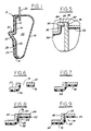
- Figure 5 is a fragmentary, enlarged sectional view of a split mould and divider means disposed in a plastisol particle casting disposition
- Figure 6 is a fragmentary, enlarged sectional view of the split mould parts disposed for removal of a charge box and divider;
- Figure 7 is a fragmentary, enlarged sectional view of the split mould parts clamped to form an integral joint between previously cast shells formed on the split mould parts by partially fused plastisol particles;
- Figure 8 is a fragmentary, enlarged sectional view of an abutting joint design of the split mould tooling.
- Figure 9 is a second embodiment of the joint design of the split mould tooling shown in Figure 9.
- Figure 1 shows a typical automobile door panel application of a multi-colour, single-piece interior plastic shell 10.
- the shell 10 preferably made of polyvinyl chloride material, is backed by a layer of polyurethane foam l2 bonded to the shell 10 by a mould process such as in USPN 3,123,403,issued March 3, 1964 for Automobile Arm Rest.
- An interior reinforcing insert 14 is connected at a joint 16 to an outer door shell 18 to form an interior space 20 for window lift mechanism (not illustrated) to raise and lower a window 22.
- the shell is a onepiece plastic part with an integral lower panel 24 of a drycast plastic having a first colour.
- the shell 10 includes an integral joint 26 which is at the base of a recesed groove 28.
- the groove 28 forms a transition to an integrally formed upper panel 30 including an armrest segment 32 formed of drycast plastic having a second colour contrasting or complementing the colour of the first panel 24 or other interior components.
- the upper panel can be red, blue, yellow or beige to contrast with or complement the interior colour of seats, headliners,instrument panels and the like.
- the lower panel 24 can be coloured a deeper complementary tone colour of a character which has a low impact or scuff display character.
- a dry plastisol moulding process line is schematically shown as including selectively heated mould 34 with split portions 35,37.
- a plastisol box 36 is operated between raised and lowered positions with respect to the mould 34 by suitable handling equipment, one type of which is specifically set forth in co-pending USSN 500,760 filed June 3, 1983 for Mould Loading Method and Apparatus.
- the box 36 further includes an upper open end 38 which is configured to cover the planar extent of a complementary opening 40 to mould 34.
- Clamp means 42 joint and seal the charge box 36 to mould 34 when the box 36 is elevated to the position shown in Figure 3, hereinafter referred to as the "mould-up" position.
- the box 36 is provided with a divider 46 and the mould 34 has its pslit portions 35, 37 movable between clamping and unclamped positions to be described.
- the divider 46 and split portions 35, 37 are in contact during plastisol casting to form two separate compartments 50, 52 each containing a charge of plastic plastisol material of a different colour (colour A in 50, colour B in 52).
- the casting process step includes concurrent rotation fo the closed system 44 by drive means 53 about axis 54 defined by trunnions means of the type set forth in co-pending USSN 500,760 through 180 degrees relative to the Figure 3 position.
- a fill step of the process is shown in which dry plastisol is distributed evenly throughout the mould opening 40.
- a resultant build-up of cast plastisol occurs on pre-heated casting surfaces 56, 58 on the split portions 35, 37, respectively, of the mould 34.
- the mould position shown in Figure 4 will hereinafter be referred to as the "mould-down" position.
- the joined mould 34 and charge box 36 are again rotated 180 degress by the drive means so that the mould 34 is located vertically above the box 36 in the mouldup position.
- An air-jet system of the type shown in the co-pending USSN 500,760 may be used to dislodge excess plastisol from the walls of the mould by the drive means so that the dislodged material will flow by gravity return to the interior of the box for collection and reuse in the system.
- a plastisol fuse cycle is then carried out in accordance with known practice wherein the plastisol particles are partially fused as a thin-walled part.
- the charge box is unclamped from the mould 34 and the split portions 35, 37 are separated by a space 60 so that the divider 46 as shown in Figure 6 and the box 36 can be removed from the mould and returned to a plastisol make-up position.
- the mould split portions 35, 37 are clamped with the plastisol cast to the surfaces 56, 58 being forced together when partially fused.
- the unit is heated further to finally fuse the plastisol, then is cooled and rotated 180 degrees into a strip position corresponding to the mould-down position. Make-up plastisol of appropriate colour is fed to the multiple separate colour compartments.
- the split portions 35, 37 and divider 46 are specially configured and sequentially, operatively positioned to produce an integral joint between plastisol cast on the respective surfaces 56, 58. More specifically, as shown in Figure 2, the split portions 35,37 have spaced supports 60, 62 and 64, 66, respectively, fixed thereto. Each of the supports 60-66 carry a bearing 68 that is slidably supported on a guide rod 70 which is supported to a mould support 71.
- a reciprocating drive unit 72 has its drive shaft 74 coupled to split portion 35 to reciprocate it through clamping and unclamping movements on rod 70 with respect to split portion 37.
- a reciprocating drive unit 76 has its drive shaft 78 connected to split portion 37 to reciprocate it through clamping and unclamping movements on rod 70 with respect to split portion 35.
- the poritions 35, 37 are moved into a first unclamped position which defines the opening 79 between a surface 80 on bent edge 82 of portion 37 and a straight edge 83 on portion 35.
- the opening 79 is sized to receive a bent end 84 of the divider 46 as the mould 34 and box 36 are initially joined.
- the portions 35,37 are moved by drive units 72, 76 thorugh a clamping movement in which edge 83 engages the bent end 84 at surface 86 and a surface 88 on bent end 82 engages an inboard surface 90 of end 84; all of the aforesaid surface interfaces co-operating to form the plastisol casting clamping position of Figure 5.
- the divider end 84 separates plastisol particles A cast on surface 56 from plastisol particles B cast on surface 58.
- the mould 34 and box 36 return to the Figure 3 position. As shown in Figure 6, the mould is positioned in an unclamped position which separates the split portions 35 and 37 to form the opening 79 for removing the divider 46 from the mould.
- Partially fused particles of plastisol define layers 92, 94 on the casting surfaces 56, 58 on the separated split portions 35, 37.
- the split portions 35,37 are then moved through a clamping movement which causes the layer 92 to be joined and clamped to layer 94, as shown in Figure 7.
- the layers 92, 94 are folded and/or pushed together and are finally fused to form a folded joint in a unitary, one-piece product.
- Figure 8 shows an abutting joint.
- the net tooling closure line 96 is disposed approximately midway of a plastisol layer 98 formed on the surface 80 of bent end 82.
- the end 100 of a layer 102 formed at the straight end 84 is thus abutted into and clamped to the layer 98 to form an L-shaped joint 104 therebetween.
- FIG. 9 a compression mortise joint is shown. It is formed by locating the net tooling closure line 108 at the surface 80 on bent end 82. Also, there is a vertical offset of the casting surfaces 56, 58 so that a plastisol layer 112 cast on surface 56 will form a straight line joint 114 with respect to the plastisol 116 formed on surface 80 of bent end 82.
- a typical powder casting process for a two-colour door panel includes the following sequence.
- suitable mould heating processes for use with the process and apparatus of the present invention include mould temperature control by heated and cooled air or oil heating and cooling flow as set forth in US 4,217,325 issued August 12, 1980 to D. Colby.
- Suitable thermoplastic plastisol particles include plasticised polyvinyl chlorides and related vinyl resins in dry form for ease of gravity flow from the charge box 36 during both fill and return steps.
- Typical examples of parts, plastic materials and mould processes include the following:
- Examples of parts that have been made by the dry PVC cast moulding process include a door panel shell having a mould volume of approximately 0.170m3 (six (6) cubic feet).
- PVC resin, plasticiser, stabiliser, release agents and colour pigments are combined in a high intensity mixer to produce a dry, flowable powder of each desired colour.
- the process is known in the industry as dry-blending.
- the various compound components may be selected as to type and ratio to provide the properties required both for the finished product and for ease of processing. Physical properties will not be too dissimilar from those obtained with liquid plastisol which is also used to manufacture similar products but has an inherent weakness for forming objectionable drips and runs when made in complex shapes.
- Processing properties are such that when melting of the plastic powder occurs, densification results in exact reproduction of minute detail such as grain marks and stitches engraved in the mould surface.
- Mould preheating temperature may range from 250°F to 390°F. Since the thickness of the finished product is also governed by the time the plastisol particles contact the mould, it should be understood that simultaneous charging of the particles to the split mould portions can be of definite advantage. Also, if certain areas of the mould can be made to have a lower preheated temperature than others, it will permit moulding a thinner shell in those areas, since both temperature and mould-filled time determine the final thickness of the shell. Therefore, a very flexible range, for mould-filled time, of one second to ten seconds or more has been established.
- the mould After final fusion, the mould is cooled to a temperature which will facilitate removal of the shell without damage.
- thermo-plastic plastisol material onto mould surfaces to form large, long, thin-walled single-piece two-colour or more shells for interior door panels and the like formed during short cycle mould cycles in limited plant floor space.
Landscapes
- Engineering & Computer Science (AREA)
- Mechanical Engineering (AREA)
- Moulding By Coating Moulds (AREA)
- Moulds For Moulding Plastics Or The Like (AREA)
- Lining Or Joining Of Plastics Or The Like (AREA)
Description
- This invention pertains to a process and an apparatus according to the preambles of claims 1 and 4. such a process and such an apparatus are known from FR-A- 1560675. The plastic shells made by the process and the apparatus are especially suitable for use in automobile trim components such as interier door panels.
- The automative industry has turned to the use of interior trim components such as door panels comprising a polyvinyl chloride shell. See, for example. the trim components disclosed in U.S. patent No. 3,123,403. The acceptance of such components has been because inter alia this type of construction permits a wide latitude in styling and colour, and grain effects which are most desired particularly in the interior design of automobiles.
- The current state of the art includes a pre-formed grained vinyl shell made from dry thermoplastic plastisol particles which are applied to a heated shell mould from a supply box to form a continuous monochromatic one-piece shell.
- In order to enhance the interior decor of an automobile, interior door panels and other parts have been proposed which include two separate plastic shell sections formed from different coloured plastic joined by a separate connector strip at a connection joint.
- The use of multi-colour plastic is also known in the manufacture of coloured filaments. Such manufacture includes use of a compartmented spinning head for making two-coloured yarn as disclosed in US 3, 049,397 issued August l4, 1962 for Process of Making Space-Dyed Yarn.
- Apparatus and method for multiple coloured thermoplastic floor materials are set forth in US 3,383,442 issued May 14, 1968.
- Also, the use of movable dividers in moulds for moulding products is known as practised in US 1,521,316, issued December 30, 1924, US 3,859,016, issued January 7, 1975 and US 4,335,068, issued June 15, 1982.
- None of the aforesaid methods and apparatus for manufacture of plastic products is directed to a process or apparatus for manufacturing a single piece shell product, for example, an interior panel component of an automobile.
- FR-A-1, 560,675 discloses a process for forming a single-piece plastics shell comprising:
heating an open-ended mould to a temperature near the melt temperature of a plastisol thermoplastic material connecting a change box to the mould to form a closed system including plastisol, and
subsequently rotating the charge box and mould in a plastisol casting sequence to release plastisol particles by gravity onto a casting surface of the mould to build up a fused plastisol shell of desired shape and size within the mould. - FR-A-1, 560,675 also discloses apparatus for moulding a thin-walled plastic shell in a heated open-ended mould from a charge of dry thermoplastic plastisol material in open-ended charge box means said apparatus comprising: means for joining a mould and charge box in open-ended relationship, and means for rotating the mould and charge box so as to distribute plastisol material against a carting surface of the mould.
- In one aspect the present invention provides a process as disclosed in FR-A-1,560,675 characterised by providing, prior to rotation of the charge box first and second split mould portions movable between clamping and unclamping positions with respect to each other and with respect to a mould divider for sealing an interior portion of the charge box and sealing to separate first and second casting surfaces of said first and second mould portions respectively, by releasing plastisol particles of a different colour onto each of said casting surfaces during the rotation of the charge box, to build up separate partially fixed plastisol shells of desired shape and size on the respective split mould portions; by separating the split mould portions for removal of the divider and charge box from the mould, by thereafter positioning the split mould portions together to clamp the separate, partially fused shells together and finally fixing the shells to form an integral joint therebetween and thereby form a multi-colour shell.
- In another aspect the invention provides apparatus as disclosed in FR-A-1,560,675 characterised in that said charge box comprises a single open-ended box having a divider separating the box into first and second open-end compartments which are capable of distributing two charges of different colour against respective separate casting surfaces of the mould; said mould has first and second split portions which define said first and second casting surfaces, said first and second split portions being movable to clamp and unclamp the divider, and said mould has joint-formation means including a bent end on one of said split mould portions which is engageable with said divider when in a clamped position to form a powder collection region.
- A more complete understanding of the invention will be apparent to those skilled in the art from the succeeding detailed description by way of example only of the preferred embodiments of the invention with reference to the accompanying drawings thereof.
- Figure 1 is a schematic view of a single-piece multi-colour panel formed by a method in accordance with the present invention shown with associated component parts of an automotive vehicle door panel;
- Figure 2 is a diagrammatically shown sectional view of a mould component of the apparatus of the invention in association with a charge box ;
- Figure 3 is a diagrammatically shown sectional view of a box forming part of the apparatus of the invention sealed to the mould of Figure 2 in a pre-release position;
- Figure 4 is a sectional view like Figure 3 showing the box and mould in a plastisol release orientation;
- Figure 5 is a fragmentary, enlarged sectional view of a split mould and divider means disposed in a plastisol particle casting disposition;
- Figure 6 is a fragmentary, enlarged sectional view of the split mould parts disposed for removal of a charge box and divider;
- Figure 7 is a fragmentary, enlarged sectional view of the split mould parts clamped to form an integral joint between previously cast shells formed on the split mould parts by partially fused plastisol particles;
- Figure 8 is a fragmentary, enlarged sectional view of an abutting joint design of the split mould tooling; and
- Figure 9 is a second embodiment of the joint design of the split mould tooling shown in Figure 9.
- The process and apparatus of the present invention will be described with reference to the production of plastic thin-walled shells for a typical automotive part such as an interior door panel, console panel or instrument panel.
- Figure 1 shows a typical automobile door panel application of a multi-colour, single-piece interior plastic shell 10. The shell 10, preferably made of polyvinyl chloride material, is backed by a layer of polyurethane foam l2 bonded to the shell 10 by a mould process such as in USPN 3,123,403,issued March 3, 1964 for Automobile Arm Rest. An
interior reinforcing insert 14 is connected at ajoint 16 to an outer door shell 18 to form aninterior space 20 for window lift mechanism (not illustrated) to raise and lower awindow 22. - In accordance with the present invention the shell is a onepiece plastic part with an integral
lower panel 24 of a drycast plastic having a first colour. The shell 10 includes anintegral joint 26 which is at the base of a recesedgroove 28. Thegroove 28 forms a transition to an integrally formedupper panel 30 including anarmrest segment 32 formed of drycast plastic having a second colour contrasting or complementing the colour of thefirst panel 24 or other interior components. For example, the upper panel can be red, blue, yellow or beige to contrast with or complement the interior colour of seats, headliners,instrument panels and the like. Thelower panel 24 can be coloured a deeper complementary tone colour of a character which has a low impact or scuff display character. - Referring to Figures 2-4, a dry plastisol moulding process line is schematically shown as including selectively heated
mould 34 withsplit portions plastisol box 36 is operated between raised and lowered positions with respect to themould 34 by suitable handling equipment, one type of which is specifically set forth in co-pending USSN 500,760 filed June 3, 1983 for Mould Loading Method and Apparatus. - The
box 36 further includes an upperopen end 38 which is configured to cover the planar extent of acomplementary opening 40 tomould 34. - Clamp means 42 joint and seal the
charge box 36 tomould 34 when thebox 36 is elevated to the position shown in Figure 3, hereinafter referred to as the "mould-up" position. - As a result, the interior of
box 36 and the interior ofmould 34 form a closedsystem 44 having plastisol charges in thebox 36. - In accordance with the process and aparatus of the present invention, the
box 36 is provided with adivider 46 and themould 34 has itspslit portions - The
divider 46 and splitportions separate compartments - The casting process step includes concurrent rotation fo the closed
system 44 by drive means 53 aboutaxis 54 defined by trunnions means of the type set forth in co-pending USSN 500,760 through 180 degrees relative to the Figure 3 position. - At Figure 4 a fill step of the process is shown in which dry plastisol is distributed evenly throughout the mould opening 40. A resultant build-up of cast plastisol occurs on
pre-heated casting surfaces split portions mould 34. The mould position shown in Figure 4 will hereinafter be referred to as the "mould-down" position. - Following the fill step, the joined
mould 34 andcharge box 36 are again rotated 180 degress by the drive means so that themould 34 is located vertically above thebox 36 in the mouldup position. - An air-jet system of the type shown in the co-pending USSN 500,760 may be used to dislodge excess plastisol from the walls of the mould by the drive means so that the dislodged material will flow by gravity return to the interior of the box for collection and reuse in the system.
- A plastisol fuse cycle is then carried out in accordance with known practice wherein the plastisol particles are partially fused as a thin-walled part. The charge box is unclamped from the
mould 34 and thesplit portions space 60 so that thedivider 46 as shown in Figure 6 and thebox 36 can be removed from the mould and returned to a plastisol make-up position. Thereafter the mould splitportions surfaces - In accordance with the present invention, the
split portions divider 46 are specially configured and sequentially, operatively positioned to produce an integral joint between plastisol cast on therespective surfaces split portions supports bearing 68 that is slidably supported on aguide rod 70 which is supported to a mould support 71. A reciprocatingdrive unit 72 has itsdrive shaft 74 coupled to splitportion 35 to reciprocate it through clamping and unclamping movements onrod 70 with respect to splitportion 37. Likewise, a reciprocatingdrive unit 76 has itsdrive shaft 78 connected to splitportion 37 to reciprocate it through clamping and unclamping movements onrod 70 with respect to splitportion 35. - In figure 2, the
poritions opening 79 between asurface 80 onbent edge 82 ofportion 37 and astraight edge 83 onportion 35. The opening 79 is sized to receive abent end 84 of thedivider 46 as themould 34 andbox 36 are initially joined. - Once the
bent end 84 is positioned in theopening 79, theportions drive units edge 83 engages thebent end 84 atsurface 86 and asurface 88 onbent end 82 engages aninboard surface 90 ofend 84; all of the aforesaid surface interfaces co-operating to form the plastisol casting clamping position of Figure 5. In this position, thedivider end 84 separates plastisol particles A cast onsurface 56 from plastisol particles B cast onsurface 58. - Once the plastisol is cast, the
mould 34 andbox 36 return to the Figure 3 position. As shown in Figure 6, the mould is positioned in an unclamped position which separates thesplit portions opening 79 for removing thedivider 46 from the mould. - Partially fused particles of plastisol define
layers portions split portions layer 92 to be joined and clamped to layer 94, as shown in Figure 7. Thelayers - Two typical joint-line sections are shown in Figures 8 and 9. Figure 8 shows an abutting joint. In this configuration the net
tooling closure line 96 is disposed approximately midway of aplastisol layer 98 formed on thesurface 80 ofbent end 82. Theend 100 of alayer 102 formed at thestraight end 84 is thus abutted into and clamped to thelayer 98 to form an L-shaped joint 104 therebetween. - In Figure 9 a compression mortise joint is shown. It is formed by locating the net
tooling closure line 108 at thesurface 80 onbent end 82. Also, there is a vertical offset of the casting surfaces 56, 58 so that a plastisol layer 112 cast onsurface 56 will form a straight line joint 114 with respect to theplastisol 116 formed onsurface 80 ofbent end 82. - A typical powder casting process for a two-colour door panel includes the following sequence.
- 1. Preheat tool in oven to temperature between 121° and 199° and 390°F.
- 2. After mould cast temperature is reached, attach the powder box to the mould.
- 3. Rotate box and mould.
- 4. Dwell time on top (for part thickness)
- 5. Rotate 180° and unclamp.
- 6. Clamp the split mold parts to join partially fused spearate shells and return the mould to the oven for cure.
- Examples of suitable mould heating processes for use with the process and apparatus of the present invention include mould temperature control by heated and cooled air or oil heating and cooling flow as set forth in US 4,217,325 issued August 12, 1980 to D. Colby. Suitable thermoplastic plastisol particles include plasticised polyvinyl chlorides and related vinyl resins in dry form for ease of gravity flow from the
charge box 36 during both fill and return steps. Typical examples of parts, plastic materials and mould processes include the following: - Examples of parts that have been made by the dry PVC cast moulding process include a door panel shell having a mould volume of approximately 0.170m³ (six (6) cubic feet).
- PVC resin, plasticiser, stabiliser, release agents and colour pigments are combined in a high intensity mixer to produce a dry, flowable powder of each desired colour. The process is known in the industry as dry-blending.
- The various compound components may be selected as to type and ratio to provide the properties required both for the finished product and for ease of processing. Physical properties will not be too dissimilar from those obtained with liquid plastisol which is also used to manufacture similar products but has an inherent weakness for forming objectionable drips and runs when made in complex shapes.
- Processing properties are such that when melting of the plastic powder occurs, densification results in exact reproduction of minute detail such as grain marks and stitches engraved in the mould surface.
- Mould preheating temperature may range from 250°F to 390°F. Since the thickness of the finished product is also governed by the time the plastisol particles contact the mould, it should be understood that simultaneous charging of the particles to the split mould portions can be of definite advantage. Also, if certain areas of the mould can be made to have a lower preheated temperature than others, it will permit moulding a thinner shell in those areas, since both temperature and mould-filled time determine the final thickness of the shell. Therefore, a very flexible range, for mould-filled time, of one second to ten seconds or more has been established.
- Depending on formulation, final metling or fusion of the PVC powder occurs when mould temperatures reach 177°C to 232°C (350°F to 450°F).
- After final fusion, the mould is cooled to a temperature which will facilitate removal of the shell without damage.
- Specifically the process and apparatus of the present invention enable even and complete distribution of thermo-plastic plastisol material onto mould surfaces to form large, long, thin-walled single-piece two-colour or more shells for interior door panels and the like formed during short cycle mould cycles in limited plant floor space.
Claims (5)
- A process for forming a single-piece plastics shell (10) comprising:
heating on open-ended mould (34) to a temperature near the melt temperature of a plastisol thermoplastic material; connecting a charge box (36) to the mould to form a closed system including plastisol, and subsequently rotating the charge box and mould in a plastisol casting sequence to release plastisol particles by gravity onto a casting surface (56,58) of the mould to build up a fused plastisol shell of desired shape and size within the mould, characterised by providing, prior to rotation of the charge box (36) first and second split mould portions (35,37) movable between clamping and unclamping positions with respect to each other and with respect to a mould divider (46) for sealing and interior portion of the charge box and sealing to separate first and second casting surfaces (56,58) of said first and second mould portions (35,37) respectively, by releasing plastisol particles of a different colour onto each of said casting surfaces during the rotation of the charge box, to build up separately partially fused plastisol shells (92,94) of desired shape and size on the respective split mould portions, by separating the split mould portions (35,37) for removal of the divider (46) and charge box (36) form the mould, by thereafter positioning the split mould portions (35,37) together to clamp the separate,partially fused shells (92,94) together and finally firing the shells to form an integral joint therebetween and thereby form a multi-colour shell (10) - A process according to claim 1 including
providing a first bend end (82) on one of the split mould portions (37) and a straight edge (83) on the other of the split mould portions (35);providing a divider (46) with a second bent end (84); positioning the first and second split mould portions apart to form a space (79) between the first bent end and the straight edge of a width to accommodate the second bent end therebetween; and positioning the split mould portions during casting so as to clamp the second bent end between the first bent end (82) and the straight edge (83)so as to form a pocket (90) for casting a first charge of plastisol particles against all of the inboard surface of the first bent end at one casting surface and across all the inboard surface of the other casting surface. - A process according to claim 2, including
locating the straight edge (83) at the mid-point of a plastisol shell (98) cast on the first bent end (82) and locating the shell (102) cast on the other casting surface to extend from the plane (96) of the end of the first bent end (82) during clamping of the partially fused shells so as to form an integral L-shaped abutting joint (104) between the first and second shells following final fusion. - Apparatus for moulding a thin-walled plastic shell (10) in a heated open-ended mould (34) from a charge of dry thermoplastic plastisol material in open-ended charge box means (36) said apparatus comprising: means (42) for joining a mould (34) and charge box (36) in open-ended relationship, and means (53) for rotating the mould and charge box so as to distribute plastisol material against a casting surface (56,58) of the mould; characterised in that :
said charge box (36) comprises a single open-end box having a divider (46) separating the box into first (50) and second (52) open-end compartments which are capable of distributing two charges of different colour against respective separate casting surfaces (56,58) of the mould (34); said mould has first (35) and second (37) split portions which define said first and second casting surfaces,said first and second split portions being movable to clamp and unclamp the divider, and said mould has joint-formation means (82,83,84) including a bent end (82) on one (37) of said split mould portions which is engageable with paid divider (43) when in a clamped position to form a powder collection region. - Apparatus according to claim 4 including means (72,76) for unclamping said split portions (35,37) of said mould (34) from the divider to permit separation of said charge box (36) from said mould, and means (72,76) for clamping said split portions (35,37) to cause separate plastisol shells (92,94) cast thereon to be finally fused to form an integral joint (104,114) between such shells.
Applications Claiming Priority (2)
| Application Number | Priority Date | Filing Date | Title |
|---|---|---|---|
| US794805 | 1985-11-04 | ||
| US06/794,805 US4634360A (en) | 1985-11-04 | 1985-11-04 | Rotational mold for making multi-color plastic shells |
Publications (3)
| Publication Number | Publication Date |
|---|---|
| EP0223359A2 EP0223359A2 (en) | 1987-05-27 |
| EP0223359A3 EP0223359A3 (en) | 1988-07-20 |
| EP0223359B1 true EP0223359B1 (en) | 1991-04-03 |
Family
ID=25163734
Family Applications (1)
| Application Number | Title | Priority Date | Filing Date |
|---|---|---|---|
| EP86307117A Expired - Lifetime EP0223359B1 (en) | 1985-11-04 | 1986-09-16 | Mold method and split mold apparatus for multi-color plastic shells |
Country Status (7)
| Country | Link |
|---|---|
| US (1) | US4634360A (en) |
| EP (1) | EP0223359B1 (en) |
| JP (1) | JPS62111708A (en) |
| AU (1) | AU594073B2 (en) |
| CA (1) | CA1260662A (en) |
| DE (1) | DE3678535D1 (en) |
| MX (1) | MX163589B (en) |
Families Citing this family (23)
| Publication number | Priority date | Publication date | Assignee | Title |
|---|---|---|---|---|
| JPS6124419A (en) * | 1984-07-14 | 1986-02-03 | Toyota Motor Corp | Slush mold |
| DE3520152A1 (en) * | 1985-06-05 | 1986-12-18 | Ymos Aktiengesellschaft Industrieprodukte, 6053 Obertshausen | METHOD AND DEVICE FOR PRODUCING A PLASTIC SKIN |
| US4780345A (en) * | 1985-10-30 | 1988-10-25 | Davidson Textron Inc. | Mold method and apparatus for multi-color plastic shells |
| AU610194B2 (en) * | 1987-07-16 | 1991-05-16 | Davidson Textron Inc. | A method for producing a molded article having colored features |
| US4895690A (en) * | 1987-07-24 | 1990-01-23 | Davidson Textron Inc. | Method for casting colored details |
| US4882173A (en) * | 1987-07-24 | 1989-11-21 | Davidson Textron Inc. | Apparatus for molding thermoplastic material |
| DE4029254A1 (en) * | 1990-09-14 | 1992-03-19 | Benecke Ag J H | METHOD FOR PRODUCING MULTICOLORED SLUSH SKINS AND FORM AND SEPARATING DEVICE FOR CARRYING OUT THE METHOD |
| IT1245843B (en) * | 1990-09-17 | 1994-10-25 | Ilpea Ind Spa | PROCESS FOR MOLD FORMING BY WASTE REFUSED CASTING, SUCH AS FAKE SKIN OR SIMILAR, WITH TWO OR MORE COLORS, FROM THERMOPLASTIC RESINS, THERMO-HARDENERS OR ELASTOMERS IN POWDER, MANUFACTURED SO OBTAINED AND PROCESSING EQUIPMENT. |
| US5395578A (en) * | 1990-09-17 | 1995-03-07 | Industrie Ilpea S.P.A. | Method for slush molding articles, of two or more colors from thermoplastic, thermosetting or elastomeric resins in powder form |
| GB2288359B (en) * | 1994-04-08 | 1997-08-13 | Martin Spencer | Rotational moulding |
| US5911938A (en) * | 1997-02-12 | 1999-06-15 | Windsor Industries, Inc. | Rotational molding with removable fixture |
| ATE261806T1 (en) | 1997-06-16 | 2004-04-15 | Magna Interior Sys Inc | DECORATIVE INTERIOR CLOTHING ELEMENTS FOR MOTOR VEHICLES WITH A CAST LIGHT STABLE COVERING, PROVIDED WITH AN INVISIBLE TEAR LINE AND METHOD FOR PRODUCING THE SAME |
| EP0893224B1 (en) * | 1997-07-24 | 2004-12-29 | Benecke-Kaliko Aktiengesellschaft | Slush moulding of airbag cover with a tear line |
| US6082989A (en) | 1998-11-13 | 2000-07-04 | Mcnally; Douglas J. | Slush molding apparatus |
| US6284182B1 (en) | 1999-03-12 | 2001-09-04 | Konal Engineering And Equipment Inc. | Molding process employing heated fluid |
| US6383437B1 (en) | 1999-09-30 | 2002-05-07 | Thomas G. Grieve | Rotational moulding method and apparatus for making multi color plastic articles |
| US6524509B1 (en) | 2000-08-16 | 2003-02-25 | Textron Automotive Company Inc. | Method for casting multicolored parts for automotive interior applications |
| CN1974169B (en) * | 2001-02-05 | 2012-02-29 | 3Dm全球有限公司 | Plastic composite article |
| US20050244610A1 (en) * | 2004-04-29 | 2005-11-03 | Visteon Global Technologies, Inc. | Injection molding of components for vehicles |
| GB2436914B (en) * | 2006-03-11 | 2011-01-05 | Gordon Ellis & Co | Rotational moulding method |
| KR101252355B1 (en) * | 2010-11-03 | 2013-04-08 | 경북대학교 산학협력단 | Composition for diagnosing lung cancer comprising an agent for determining level of methylation of RGC32 gene and a method for diagnosing lung cancer using the same |
| CN103978600B (en) * | 2013-02-07 | 2016-06-08 | 应革 | Automatic die sinking one-shot forming rotational molding car body die |
| MX2020004029A (en) | 2017-10-20 | 2020-08-13 | Jfe Steel Corp | High-strength steel sheet and manufacturing method thereof. |
Citations (1)
| Publication number | Priority date | Publication date | Assignee | Title |
|---|---|---|---|---|
| FR1560675A (en) * | 1967-02-27 | 1969-03-21 |
Family Cites Families (17)
| Publication number | Priority date | Publication date | Assignee | Title |
|---|---|---|---|---|
| US178308A (en) * | 1876-06-06 | Improvement in processes, patterns | ||
| US2115249A (en) * | 1936-04-08 | 1938-04-26 | William C Bowman | Process of forming commercial articles |
| GB968760A (en) * | 1962-08-29 | 1964-09-02 | Standard Pressed Steel Co | Improvements in producing articles having a plurality of surface portions of different colours, particularly seat or other upholstery coverings |
| US3796622A (en) * | 1970-07-10 | 1974-03-12 | N Brody | Colored plastic article and method of production |
| GB1351760A (en) * | 1970-11-13 | 1974-05-01 | Exxon Research Engineering Co | Process and apparatus for producing hollow articles |
| US3914361A (en) * | 1972-06-29 | 1975-10-21 | Furukawa Electric Co Ltd | Method for rotational molding of composite foamed plastic articles |
| JPS538569B2 (en) * | 1974-12-28 | 1978-03-30 | ||
| DE2501291A1 (en) * | 1975-01-15 | 1976-07-22 | Roehm Gmbh | Injection moulding of hollow bodies - using three-part injection mould |
| ES455627A1 (en) * | 1977-01-26 | 1978-01-01 | Mares Ibanez Pedro | Process and apparatus for forming compound structure of various plastic materials in mold having apertured slide plate |
| US4191726A (en) * | 1977-06-24 | 1980-03-04 | Gebrueder Buehler Ag | Process and apparatus for manufacturing molded parts from granulated plastic materials |
| FR2402523A1 (en) * | 1977-09-12 | 1979-04-06 | Bonnet Emmanuel | Complementary moulds for casting non-planar mouldings - esp. GRP vehicle bodies, using tools which assemble partially celled castings for integral joints |
| FR2412400A1 (en) * | 1977-12-23 | 1979-07-20 | Allibert Exploitation | PROCESS FOR MOLDING CONTAINERS IN AT LEAST TWO DIFFERENT PLASTIC MATERIALS, MACHINE FOR IMPLEMENTING THIS PROCESS AND CONTAINERS OBTAINED |
| US4460530A (en) * | 1979-07-09 | 1984-07-17 | Teledyne Industries, Inc. | Method for producing porous shaped products |
| US4389177A (en) * | 1979-07-12 | 1983-06-21 | Mccord Corporation | Modular slush molding machine |
| US4275028A (en) * | 1980-01-24 | 1981-06-23 | Holiday Industries, Inc. | Plastic ornament and method of making same |
| DE3043245C2 (en) * | 1980-11-15 | 1983-04-14 | Dynamit Nobel Ag, 5210 Troisdorf | Method of making a patterned sheet of thermoplastic material |
| JPS60189431A (en) * | 1984-03-09 | 1985-09-26 | Toyota Motor Corp | Manufacture of hollow product |
-
1985
- 1985-11-04 US US06/794,805 patent/US4634360A/en not_active Expired - Fee Related
-
1986
- 1986-08-13 AU AU61096/86A patent/AU594073B2/en not_active Ceased
- 1986-09-11 MX MX3712A patent/MX163589B/en unknown
- 1986-09-16 DE DE8686307117T patent/DE3678535D1/en not_active Expired - Lifetime
- 1986-09-16 EP EP86307117A patent/EP0223359B1/en not_active Expired - Lifetime
- 1986-09-19 CA CA000518627A patent/CA1260662A/en not_active Expired
- 1986-10-16 JP JP61244308A patent/JPS62111708A/en active Pending
Patent Citations (1)
| Publication number | Priority date | Publication date | Assignee | Title |
|---|---|---|---|---|
| FR1560675A (en) * | 1967-02-27 | 1969-03-21 |
Also Published As
| Publication number | Publication date |
|---|---|
| CA1260662A (en) | 1989-09-26 |
| US4634360A (en) | 1987-01-06 |
| MX163589B (en) | 1992-06-04 |
| EP0223359A2 (en) | 1987-05-27 |
| DE3678535D1 (en) | 1991-05-08 |
| JPS62111708A (en) | 1987-05-22 |
| AU594073B2 (en) | 1990-03-01 |
| EP0223359A3 (en) | 1988-07-20 |
| AU6109686A (en) | 1987-05-07 |
Similar Documents
| Publication | Publication Date | Title |
|---|---|---|
| US4562025A (en) | Mold method and apparatus for multi-color plastic shells | |
| US4634360A (en) | Rotational mold for making multi-color plastic shells | |
| US4610620A (en) | Apparatus for molding plural colored plastic hollow shells | |
| US5316715A (en) | Method and apparatus for producing multi-color shells utilizing an indexing divider mold | |
| US4780345A (en) | Mold method and apparatus for multi-color plastic shells | |
| US4692293A (en) | Mold method for multi-color plastic shells | |
| US4925151A (en) | Apparatus for molding two-tone colored plastic shells | |
| US4755333A (en) | Mold method and apparatus for plastic shells | |
| US4894004A (en) | Apparatus for molding multi-colored plastic shells | |
| EP0339222B1 (en) | Apparatus for molding two-tone colored plastic shells | |
| RU2010713C1 (en) | Device for molding two-color thin-walled shells | |
| EP0208432B1 (en) | Mould method and apparatus for plastic shells | |
| EP0476742B2 (en) | Method for slush moulding articles, such as simulated leather or similar articles, of two or more colours from thermoplastic, thermosetting or elastomeric resins in powder form and apparatus for implementing the method. | |
| US5922256A (en) | Molding method for making plastic foam-backed shells | |
| EP0576811A1 (en) | Laterally adjustable divider wall for molding two color shells | |
| US4938906A (en) | Process for molding multi-colored plastic shells | |
| EP0307005B1 (en) | Multi-colour plastic shells | |
| CA1271611A (en) | Multi-color plastic shells | |
| CA1249317A (en) | Integrally cast plural colored plastic shells for automobile parts |
Legal Events
| Date | Code | Title | Description |
|---|---|---|---|
| PUAI | Public reference made under article 153(3) epc to a published international application that has entered the european phase |
Free format text: ORIGINAL CODE: 0009012 |
|
| AK | Designated contracting states |
Kind code of ref document: A2 Designated state(s): DE FR GB IT SE |
|
| PUAL | Search report despatched |
Free format text: ORIGINAL CODE: 0009013 |
|
| AK | Designated contracting states |
Kind code of ref document: A3 Designated state(s): DE FR GB IT SE |
|
| 17P | Request for examination filed |
Effective date: 19881117 |
|
| RAP1 | Party data changed (applicant data changed or rights of an application transferred) |
Owner name: DAVIDSON TEXTRON INC |
|
| 17Q | First examination report despatched |
Effective date: 19890526 |
|
| GRAA | (expected) grant |
Free format text: ORIGINAL CODE: 0009210 |
|
| AK | Designated contracting states |
Kind code of ref document: B1 Designated state(s): DE FR GB IT SE |
|
| REF | Corresponds to: |
Ref document number: 3678535 Country of ref document: DE Date of ref document: 19910508 |
|
| ITF | It: translation for a ep patent filed | ||
| ET | Fr: translation filed | ||
| PGFP | Annual fee paid to national office [announced via postgrant information from national office to epo] |
Ref country code: FR Payment date: 19910813 Year of fee payment: 6 |
|
| PGFP | Annual fee paid to national office [announced via postgrant information from national office to epo] |
Ref country code: SE Payment date: 19910816 Year of fee payment: 6 |
|
| PGFP | Annual fee paid to national office [announced via postgrant information from national office to epo] |
Ref country code: DE Payment date: 19910822 Year of fee payment: 6 |
|
| PGFP | Annual fee paid to national office [announced via postgrant information from national office to epo] |
Ref country code: GB Payment date: 19910829 Year of fee payment: 6 |
|
| PLBE | No opposition filed within time limit |
Free format text: ORIGINAL CODE: 0009261 |
|
| STAA | Information on the status of an ep patent application or granted ep patent |
Free format text: STATUS: NO OPPOSITION FILED WITHIN TIME LIMIT |
|
| 26N | No opposition filed | ||
| PG25 | Lapsed in a contracting state [announced via postgrant information from national office to epo] |
Ref country code: GB Effective date: 19920916 |
|
| PG25 | Lapsed in a contracting state [announced via postgrant information from national office to epo] |
Ref country code: SE Effective date: 19920917 |
|
| GBPC | Gb: european patent ceased through non-payment of renewal fee |
Effective date: 19920916 |
|
| PG25 | Lapsed in a contracting state [announced via postgrant information from national office to epo] |
Ref country code: FR Effective date: 19930528 |
|
| PG25 | Lapsed in a contracting state [announced via postgrant information from national office to epo] |
Ref country code: DE Effective date: 19930602 |
|
| REG | Reference to a national code |
Ref country code: FR Ref legal event code: ST |
|
| EUG | Se: european patent has lapsed |
Ref document number: 86307117.1 Effective date: 19930406 |
|
| PG25 | Lapsed in a contracting state [announced via postgrant information from national office to epo] |
Ref country code: IT Free format text: LAPSE BECAUSE OF NON-PAYMENT OF DUE FEES;WARNING: LAPSES OF ITALIAN PATENTS WITH EFFECTIVE DATE BEFORE 2007 MAY HAVE OCCURRED AT ANY TIME BEFORE 2007. THE CORRECT EFFECTIVE DATE MAY BE DIFFERENT FROM THE ONE RECORDED. Effective date: 20050916 |